Page 973 of 2870

EX(H4SO)-5
EXHAUST
General Description
(1) Front exhaust pipe upper cover
CTR(15) Rear exhaust upper cover (31) Front catalytic converter upper
cover
(16) Rear exhaust lower cover
(2) Front exhaust pipe lower cover
CTR(17) Rear catalytic lower converter
cover(32) Front oxygen (A/F) sensor
(33) Rear oxygen sensor
(3) Clamp (18) Clamp (34) Clamp
(4) Front exhaust pipe upper cover LH (19) Cushion rubber
(5) Front exhaust pipe lower cover LH (20) Rear exhaust pipeTightening torque: N
⋅m (kgf-m, ft-lb)
(6) Front exhaust pipe (21) GasketT1: 8 (0.8, 5.8)
(7) Front exhaust pipe lower cover RH (22) Self-locking nutT2: 13 (1.3, 9.4)
(8) Front exhaust pipe upper cover
RH(23) MufflerT3: 18 (1.8, 13.0)
(24) ProtectorT4: 21 (2.1, 15.2)
(9) Gasket (25) GasketT5: 30 (3.1, 22.4)
(10) Gasket (26) Front catalytic converterT6: 35 (3.6, 26.0)
(11) Spring (27) Center exhaust lower coverT7: 48 (4.9, 35.4)
(12) Chamber (28) Center exhaust upper cover
(13) Rear catalytic converter (29) Center exhaust pipe
(14) Rear catalytic converter upper
cover(30) Front catalytic converter lower
cover
Page 974 of 2870
EX(H4SO)-6
EXHAUST
General Description
B: CAUTION
Wear working clothing, including a cap, protec-
tive goggles, and protective shoes during opera-
tion.
Remove contamination including dirt and corro-
sion before removal, installation or disassembly.
Keep the disassembled parts in order and pro-
tect them from dust or dirt.
Before removal, installation or disassembly, be
sure to clarify the failure. Avoid unnecessary re-
moval, installation, disassembly, and replacement.
Be careful not to burn your hands, because each
part on the vehicle is hot after running.
Be sure to tighten fasteners including bolts and
nuts to the specified torque.
Place shop jacks or rigid racks at the specified
points.
Before disconnecting electrical connectors of
sensors or units, be sure to disconnect the ground
cable from battery.
Page 975 of 2870
EX(H4SO)-7
EXHAUST
Front Exhaust Pipe
2. Front Exhaust Pipe
A: REMOVAL
1) Disconnect the ground cable from battery.
2) Disconnect the front oxygen (A/F) sensor con-
nector.
3) Disconnect the rear oxygen sensor connector.4) Lift-up the vehicle.
5) Separate the front and center exhaust pipe as-
sembly from rear exhaust pipe.
CAUTION:
Be careful, the exhaust pipe is hot.
6) Remove the under cover.
7) Remove the nuts which hold front exhaust pipe
onto cylinder heads.
8) Remove the bolt which installs front and center
exhaust pipe assembly to hanger bracket.
FU-00009
EX-00029
EX-00030
EX-00037
EC-00009
EX-00038
Page 976 of 2870

EX(H4SO)-8
EXHAUST
Front Exhaust Pipe
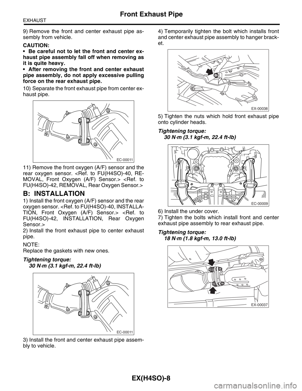
9) Remove the front and center exhaust pipe as-
sembly from vehicle.
CAUTION:
Be careful not to let the front and center ex-
haust pipe assembly fall off when removing as
it is quite heavy.
After removing the front and center exhaust
pipe assembly, do not apply excessive pulling
force on the rear exhaust pipe.
10) Separate the front exhaust pipe from center ex-
haust pipe.
11) Remove the front oxygen (A/F) sensor and the
rear oxygen sensor.
MOVAL, Front Oxygen (A/F) Sensor.>
FU(H4SO)-42, REMOVAL, Rear Oxygen Sensor.>
B: INSTALLATION
1) Install the front oxygen (A/F) sensor and the rear
oxygen sensor.
TION, Front Oxygen (A/F) Sensor.>
FU(H4SO)-42, INSTALLATION, Rear Oxygen
Sensor.>
2) Install the front exhaust pipe to center exhaust
pipe.
NOTE:
Replace the gaskets with new ones.
Tightening torque:
30 N
⋅m (3.1 kgf-m, 22.4 ft-lb)
3) Install the front and center exhaust pipe assem-
bly to vehicle.4) Temporarily tighten the bolt which installs front
and center exhaust pipe assembly to hanger brack-
et.
5) Tighten the nuts which hold front exhaust pipe
onto cylinder heads.
Tightening torque:
30 N
⋅m (3.1 kgf-m, 22.4 ft-lb)
6) Install the under cover.
7) Tighten the bolts which install front and center
exhaust pipe assembly to rear exhaust pipe.
Tightening torque:
18 N
⋅m (1.8 kgf-m, 13.0 ft-lb)
EC-00011
EC-00011
EX-00038
EC-00009
EX-00037
Page 977 of 2870
EX(H4SO)-9
EXHAUST
Front Exhaust Pipe
8) Tighten the bolt which holds front and center ex-
haust pipe assembly to hanger bracket.
Tightening torque:
35 N
⋅m (3.6 kgf-m, 26.0 ft-lb)
9) Lower the vehicle.
10) Connect the rear oxygen sensor connector.
11) Connect the front oxygen (A/F) sensor connec-
tor.
12) Connect the battery ground cable to battery.
C: INSPECTION
1) Make sure there are no exhaust leaks from con-
nections and welds.
2) Make sure there are no holes or rusting.
EX-00038
EX-00030
EX-00029
FU-00009
Page 993 of 2870
CO(H4SO)-10
COOLING
General Description
C: CAUTION
Wear working clothing, including a cap, protec-
tive goggles, and protective shoes during opera-
tion.
Remove contamination including dirt and corro-
sion before removal, installation or disassembly.
Keep the disassembled parts in order and pro-
tect them from dust or dirt.
Before removal, installation or disassembly, be
sure to clarify the failure. Avoid unnecessary re-
moval, installation, disassembly, and replacement.
Be careful not to burn your hands, because each
part in the vehicle is hot after running.
Be sure to tighten fasteners including bolts and
nuts to the specified torque.
Place shop jacks or rigid racks at the specified
points.
Before disconnecting electrical connectors of
sensors or units, be sure to disconnect the ground
cable from battery.
Page 1005 of 2870
CO(H4SO)-22
COOLING
Water Pump
2. TURBO MODEL
1) Remove the radiator.
REMOVAL, Radiator.>
2) Remove the V-belts.
REMOVAL, V-belt.>
3) Remove the timing belt.
58, REMOVAL, Timing Belt Assembly.>
4) Remove the automatic belt tension adjuster (A).
5) Remove the belt idler (B).
6) Remove the belt idler No. 2 (C).
7) Remove the camshaft position sensor. (2.0 L mod-
el)
shaft Position Sensor.>
8) Remove the cam sprockets (LH) by using ST.
ST 499977500 CAM SPROCKET WRENCH
(Intake)
ST 499207400 CAM SPROCKET WRENCH
(Exhaust)9) Remove the belt cover No. 2 (LH).
10) Remove the tensioner bracket.
11) Disconnect the hose from water pump.
12) Remove the water pump.
CO-00023
(A)
(B)
(C)
ME-00710
ME-00709
CO-00024
CO-00025
CO-00021
Page 1007 of 2870

CO(H4SO)-24
COOLING
Water Pump
9) Install the V-belts.
STALLATION, V-belt.>
10) Install the radiator.
STALLATION, Radiator.>
2. TURBO MODEL
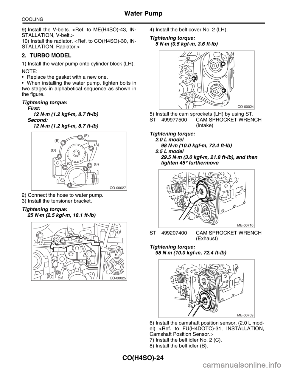
1) Install the water pump onto cylinder block (LH).
NOTE:
Replace the gasket with a new one.
When installing the water pump, tighten bolts in
two stages in alphabetical sequence as shown in
the figure.
Tightening torque:
First:
12 N
⋅m (1.2 kgf-m, 8.7 ft-lb)
Second:
12 N
⋅m (1.2 kgf-m, 8.7 ft-lb)
2) Connect the hose to water pump.
3) Install the tensioner bracket.
Tightening torque:
25 N
⋅m (2.5 kgf-m, 18.1 ft-lb)4) Install the belt cover No. 2 (LH).
Tightening torque:
5 N
⋅m (0.5 kgf-m, 3.6 ft-lb)
5) Install the cam sprockets (LH) by using ST.
ST 499977500 CAM SPROCKET WRENCH
(Intake)
Tightening torque:
2.0 L model
98 N
⋅m (10.0 kgf-m, 72.4 ft-lb)
2.5 L model
29.5 N
⋅m (3.0 kgf-m, 21.8 ft-lb), and then
tighten 45
° furthermove
ST 499207400 CAM SPROCKET WRENCH
(Exhaust)
Tightening torque:
98 N
⋅m (10.0 kgf-m, 72.4 ft-lb)
6) Install the camshaft position sensor. (2.0 L mod-
el)
Camshaft Position Sensor.>
7) Install the belt idler No. 2 (C).
8) Install the belt idler (B).
CO-00027
(B) (C) (D)(E)(F)
(A)
CO-00025
CO-00024
ME-00710
ME-00709