Page 2447 of 3870
Fig. 16: Identifying Connector C
-120
Courtesy of MITSUBISHI MOTOR SALES OF AMERICA.
2. When the resistance between the sensor terminals is measured under two
or more temperature conditions, the resistance should approximately
satisfy the illustrated values.
NOTE: The temperature conditions when checking should
not exceed the range shown in the diagram.
2004 Mitsubishi Endeavor LS
2004 HVAC Automatic Air Conditioning - Endeavor
Page 2513 of 3870
Fig. 75: Identifying Connector C
-120
Courtesy of MITSUBISHI MOTOR SALES OF AMERICA.
NOTE: The temperature conditions when checking should not
exceed the range shown in the diagram.
2004 Mitsubishi Endeavor LS
2004 HVAC Automatic Air Conditioning - Endeavor
Page 2519 of 3870

By operating two ignition keys that have been already registered (Refer to ON
-
VEHICLE SERVICE
).
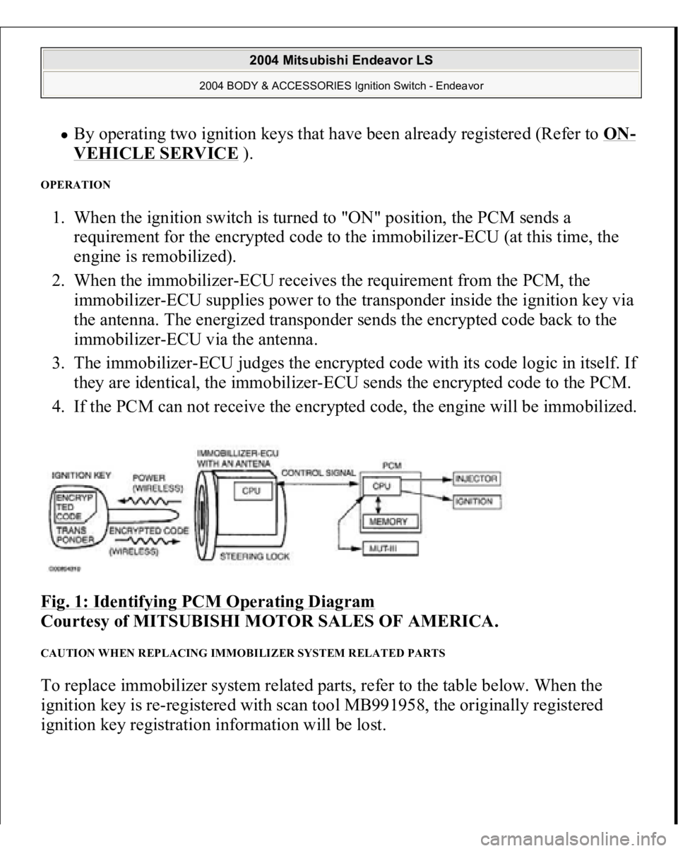
OPERATION 1. When the ignition switch is turned to "ON" position, the PCM sends a
requirement for the encrypted code to the immobilizer-ECU (at this time, the
engine is remobilized).
2. When the immobilizer-ECU receives the requirement from the PCM, the
immobilizer-ECU supplies power to the transponder inside the ignition key via
the antenna. The energized transponder sends the encrypted code back to the
immobilizer-ECU via the antenna.
3. The immobilizer-ECU judges the encrypted code with its code logic in itself. If
they are identical, the immobilizer-ECU sends the encrypted code to the PCM.
4. If the PCM can not receive the encrypted code, the engine will be immobilized.
Fig. 1: Identifying PCM Operating Diagram
Courtesy of MITSUBISHI MOTOR SALES OF AMERICA.
CAUTION WHEN REPLACING IMMOBILIZER SYSTEM RELATED PARTS To replace immobilizer system related parts, refer to the table below. When the
ignition key is re-registered with scan tool MB991958, the originally registered
ignition key registration information will be lost.
2004 Mitsubishi Endeavor LS
2004 BODY & ACCESSORIES Ignition Switch - Endeavor
Page 2521 of 3870

means of a forged key or by connecting the ignition wiring directly. The system is
significantly safe and reliable against theft. In addition, the driver has only to turn
the ignition switch to the "ON" position to activate the immobilizer system. If the
requirements for starting the engine are not satisfied, the engine will be
immobilized. If a registered ignition key is lost, all your ignition keys need to be
registered again using scan tool MB991958 (MUT-III Sub Assembly) to ensure
security (Refer to ON
-VEHICLE SERVICE
). An additional ignition key can be
registered as follows (only if no ignition keys are lost):
Using scan tool MB991958 (MUT-III Sub Assembly) (Refer to ON
-
VEHICLE SERVICE
).
By operating two ignition keys that have been already registered (Refer toON
-
VEHICLE SERVICE
).
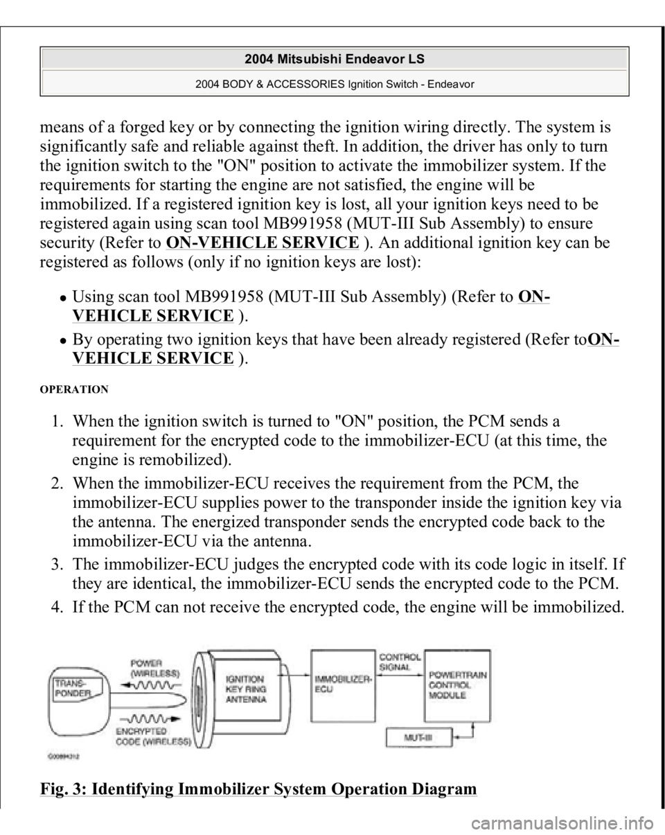
OPERATION 1. When the ignition switch is turned to "ON" position, the PCM sends a
requirement for the encrypted code to the immobilizer-ECU (at this time, the
engine is remobilized).
2. When the immobilizer-ECU receives the requirement from the PCM, the
immobilizer-ECU supplies power to the transponder inside the ignition key via
the antenna. The energized transponder sends the encrypted code back to the
immobilizer-ECU via the antenna.
3. The immobilizer-ECU judges the encrypted code with its code logic in itself. If
they are identical, the immobilizer-ECU sends the encrypted code to the PCM.
4. If the PCM can not receive the encrypted code, the engine will be immobilized.
Fig. 3: Identifying Immobilizer System Operation Diagram
2004 Mitsubishi Endeavor LS
2004 BODY & ACCESSORIES Ignition Switch - Endeavor
Page 2534 of 3870
Fig. 10: Ignition Key Ring And Immobilizer
-ECU Circuit Diagram &
Connector Identification
Courtesy of MITSUBISHI MOTOR SALES OF AMERICA.
CIRCUIT OPERATION The ignition key is powered by the ignition key ring antenna. The ignition key then
sends an encrypted code. The ignition key ring antenna receives the encrypted code,
and determines if the ignition key is registered.
2004 Mitsubishi Endeavor LS
2004 BODY & ACCESSORIES Ignition Switch - Endeavor
Page 2539 of 3870
Fig. 12: Ignition Key Ring and Immobilizer
-ECU Circuit Diagram &
Connector Identification
Courtesy of MITSUBISHI MOTOR SALES OF AMERICA.
CIRCUIT OPERATION The ignition key is powered by the ignition key ring antenna. The ignition key then
sends an encrypted code. The ignition key ring antenna receives the encrypted code,
and determines if the ignition key is registered. DTC SET CONDITION
DTC 11 may be output if other ignition keys are in the vicinity of the vehicle
as it is being started. The transponder's encrypted code is not sent to the immobilizer-ECU
immediately after the ignition switch is turned to "ON" position.
NOTE: DTC 11 is always output together with MFI system DTC
P0513.
2004 Mitsubishi Endeavor LS
2004 BODY & ACCESSORIES Ignition Switch - Endeavor
Page 2550 of 3870
Fig. 21: Immobilizer
-ECU Power Supply Ground and PCM Communication
Line Circuit Diagram & Connector Identification
Courtesy of MITSUBISHI MOTOR SALES OF AMERICA.
2004 Mitsubishi Endeavor LS
2004 BODY & ACCESSORIES Ignition Switch - Endeavor
Page 2573 of 3870
Fig. 42: Immobilizer
-ECU Power Supply, Ground and PCM Communication
Line Circuit Diagram & Connector Identification
Courtesy of MITSUBISHI MOTOR SALES OF AMERICA.
2004 Mitsubishi Endeavor LS
2004 BODY & ACCESSORIES Ignition Switch - Endeavor