Page 281 of 3870

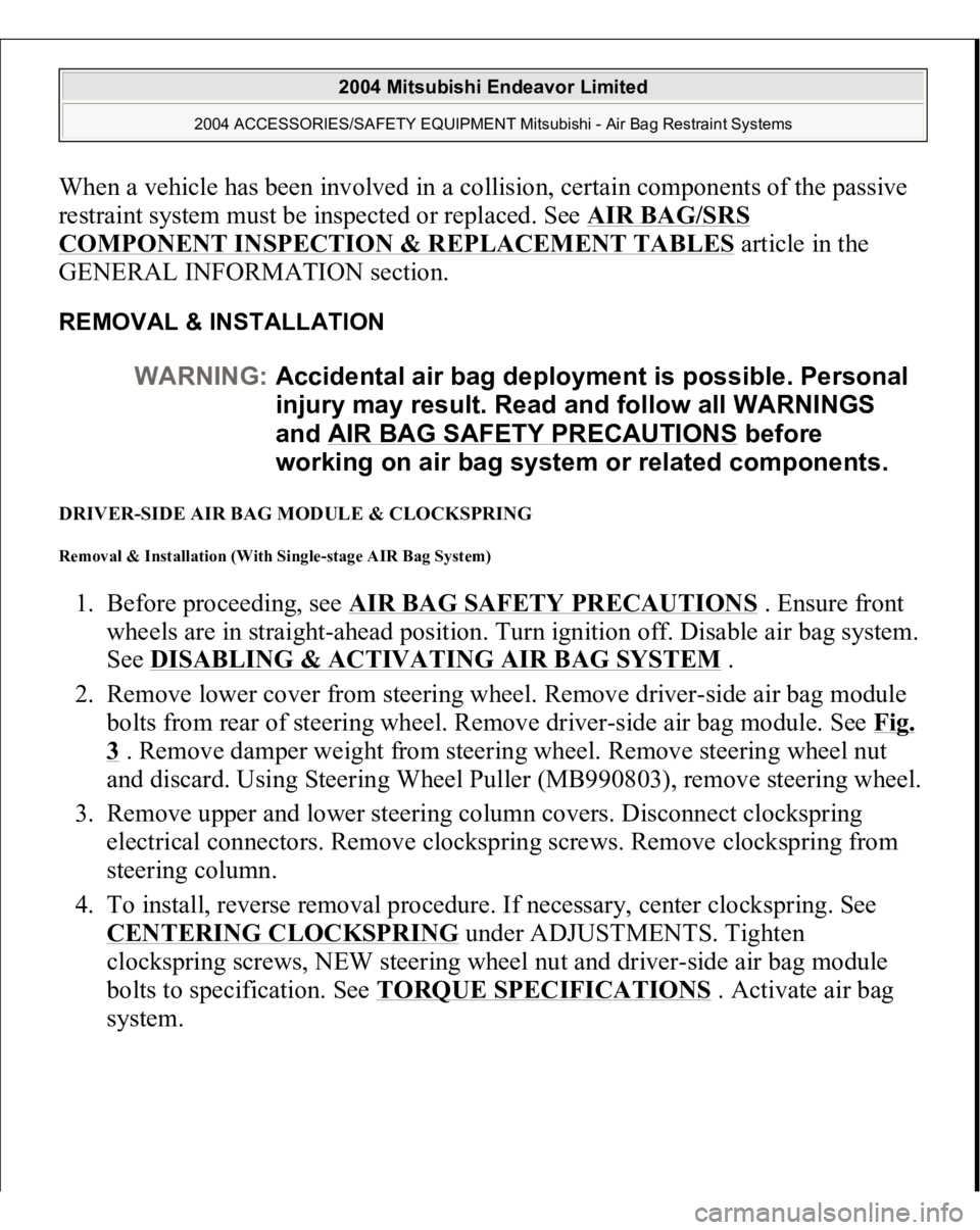
When a vehicle has been involved in a collision, certain components of the passive
restraint system must be inspected or replaced. See
AIR BAG/SRS
COMPONENT INSPECTION & REPLACEMENT TABLES
article in the
GENERAL INFORMATION section.
REMOVAL & INSTALLATION DRIVER-SIDE AIR BAG MODULE & CLOCKSPRING Removal & Installation (With Single-stage AIR Bag System) 1. Before proceeding, see
AIR BAG SAFETY PRECAUTIONS
. Ensure front
wheels are in straight-ahead position. Turn ignition off. Disable air bag system.
See
DISABLING & ACTIVATING AIR BAG SYSTEM
.
2. Remove lower cover from steering wheel. Remove driver-side air bag module
bolts from rear of steering wheel. Remove driver-side air bag module. See
Fig.
3 . Remove damper weight from steering wheel. Remove steering wheel nut
and discard. Using Steering Wheel Puller (MB990803), remove steering wheel.
3. Remove upper and lower steering column covers. Disconnect clockspring
electrical connectors. Remove clockspring screws. Remove clockspring from
steering column.
4. To install, reverse removal procedure. If necessary, center clockspring. See CENTERING CLOCKSPRING
under ADJUSTMENTS. Tighten
clockspring screws, NEW steering wheel nut and driver-side air bag module
bolts to specification. See
TORQUE SPECIFICATIONS
. Activate air bag
s
ystem. WARNING:Accidental air bag deployment is possible. Personal
injury may result. Read and follow all WARNINGS
and AIR BAG SAFETY PRECAUTIONS
before
working on air bag system or related components.
2004 Mitsubishi Endeavor Limited
2004 ACCESSORIES/SAFETY EQUIPMENT Mitsubishi - Air Bag Restraint Systems
Page 283 of 3870
steering column.
4. To install, reverse removal procedure. If necessary, center clockspring. See
CENTERING CLOCKSPRING
under ADJUSTMENTS. Tighten
clockspring screws, NEW steering wheel nut and driver-side air bag module
bolts to specification. See TORQUE SPECIFICATIONS
. Activate air bag
system.
Fig. 4: Identifying Driver
-side Air Bag Module & Clockspring (Dual
-stage Air
Bag System)
Courtesy of MITSUBISHI MOTOR SALES OF AMERICA.
FLOOR CONSOLE ASSEMBLY (WITH DUAL STAGE AIR BAG SYSTEM) Removal & Installation 1. Before proceeding, see AIR BAG SAFETY PRECAUTIONS
. Disable air
bag system. See DISABLING & ACTIVATING AIR BAG SYSTEM
.
2. Remove inner box tray. See Fig. 5
. Remove plate. Remove cup holder,
Remove left and right side covers. Remove gearshift lever panel. Remove
accessory panel. Remove rear A/C switch and accessory socket. Remove floor
console assembl
y.
2004 Mitsubishi Endeavor Limited
2004 ACCESSORIES/SAFETY EQUIPMENT Mitsubishi - Air Bag Restraint Systems
Page 1945 of 3870
Fig. 4: Special Tools (2 Of 2)
Courtesy of MITSUBISHI MOTOR SALES OF AMERICA.
ON-VEHICLE SERVICE FRONT WHEEL ALIGNMENT CHECK AND ADJUSTMENT Measure wheel alignment with alignment equipment on a level surface. The front
sus
pension, steerin
g system, wheels, and tires should be serviced to normal
CAUTION: On vehicles with ASC, if the wheel alignment is
adjusted, always carry out steering wheel sensor
calibration (STEERING WHEEL SENSOR
CALIBRATION
). This is necessary because the
TCL/ASC-ECU should update the steering neutral
point.
2004 Mitsubishi Endeavor LS 2004 SUSPENSION Front - Endeavor
Page 2378 of 3870

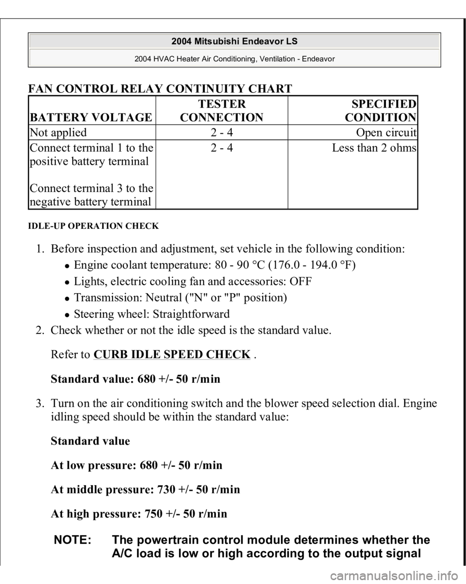
FAN CONTROL RELAY CONTINUITY CHART
IDLE-UP OPERATION CHECK 1. Before inspection and adjustment, set vehicle in the following condition:
Engine coolant temperature: 80 - 90 °C (176.0 - 194.0 °F) Lights, electric cooling fan and accessories: OFF Transmission: Neutral ("N" or "P" position) Steering wheel: Straightforward
2. Check whether or not the idle speed is the standard value.
Refer to
CURB IDLE SPEED CHECK
.
Standard value: 680 +/- 50 r/min
3. Turn on the air conditioning switch and the blower speed selection dial. Engine
idling speed should be within the standard value:
Standard value
At low pressure: 680 +/- 50 r/min
At middle pressure: 730 +/- 50 r/min
At high pressure: 750 +/- 50 r/min
BATTERY VOLTAGE
TESTER
CONNECTION
SPECIFIED
CONDITION
Not applied
2 - 4
Open circuit
Connect terminal 1 to the
positive battery terminal
Connect terminal 3 to the
negative battery terminal
2 - 4
Less than 2 ohms
NOTE: The powertrain control module determines whether the
A/C load is low or high according to the output signal
2004 Mitsubishi Endeavor LS
2004 HVAC Heater Air Conditioning, Ventilation - Endeavor
Page 2822 of 3870
NO: Go to Step 5.
STEP 5. Check for oil leaks.
Q: Are there oil leaks?
YES: Find the cause of the oil leakage and repair it. Then go to Step 9 .
NO: Go to Step 6.
STEP 6. Check the wheel alignment (camber and caster).
Refer to FRONT WHEEL ALIGNMENT CHECK AND ADJUSTMENT
.
Q: Is the alignment incorrect?
YES: Adjust alignment. Then go to Step 9 .
NO: Go to Step 7.
STEP 7. Check the gear box rack piston seal for damage.
Q: Is there damage?
YES: Replace it. Then go to Step 9 .
NO: Go to Step 8.
STEP 8. Check for excessive tie rod end ball joint breakaway torque.
Refer to TIE ROD END BALL JOINT BREAKAWAY TORQUE
CHECK
.
Q: Is the breakaway torque out of specification?
YES: Replace the tie rod end. Then go to Step 9.
NO: Go to Step 9.
STEP 9. Check the steering wheel operation.
Verify that the steering wheel operation is not difficult.
Q: Is the steering wheel operation difficult?
2004 Mitsubishi Endeavor LS
2004 STEERING Power Steering - Endeavor
Page 3521 of 3870

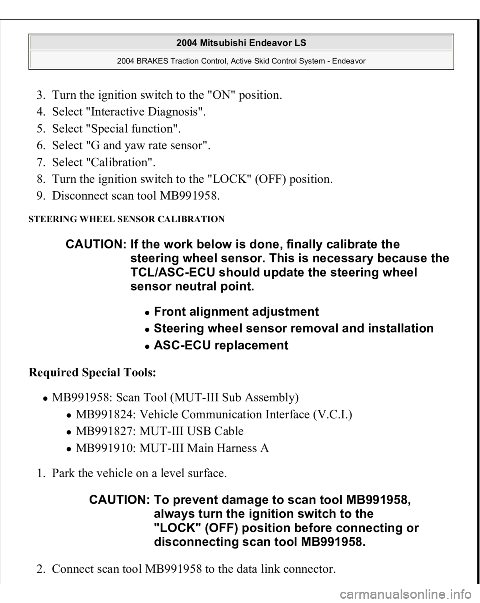
3. Turn the ignition switch to the "ON" position.
4. Select "Interactive Diagnosis".
5. Select "Special function".
6. Select "G and yaw rate sensor".
7. Select "Calibration".
8. Turn the ignition switch to the "LOCK" (OFF) position.
9. Disconnect scan tool MB991958. STEERING WHEEL SENSOR CALIBRATION Required Special Tools:
MB991958: Scan Tool (MUT-III Sub Assembly)
MB991824: Vehicle Communication Interface (V.C.I.) MB991827: MUT-III USB Cable MB991910: MUT-III Main Harness A
1. Park the vehicle on a level surface.
2. Connect scan tool MB991958 to the data link connec
tor. CAUTION: If the work below is done, finally calibrate the
steering wheel sensor. This is necessary because the
TCL/ASC-ECU should update the steering wheel
sensor neutral point.
Front alignment adjustment Steering wheel sensor removal and installation ASC-ECU replacement
CAUTION: To prevent damage to scan tool MB991958,
always turn the ignition switch to the
"LOCK" (OFF) position before connecting or
disconnecting scan tool MB991958.
2004 Mitsubishi Endeavor LS
2004 BRAKES Traction Control, Active Skid Control System - Endeavor