Page 3799 of 4264

ON-VEHICLE SERVICE (AW30 –40LE) 7A3-43
Removal
NOTE: Before removing transmission and transfer
assembly from vehicle, change the transfer mode to
2WD using the 4WD push button switch on dash panel.
1. Disconnect battery ground cable.
2. Raise and support vehicle with suitable stands.
3. Remove front propeller shaft.(4WD only)
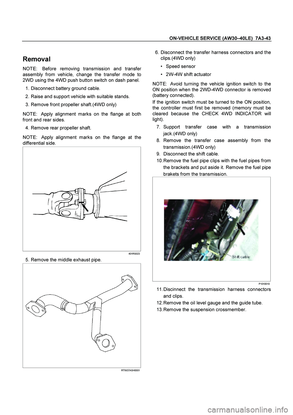
NOTE: Apply alignment marks on the flange at both
front and rear sides.
4. Remove rear propeller shaft.
NOTE: Apply alignment marks on the flange at the
differential side.
401RS023
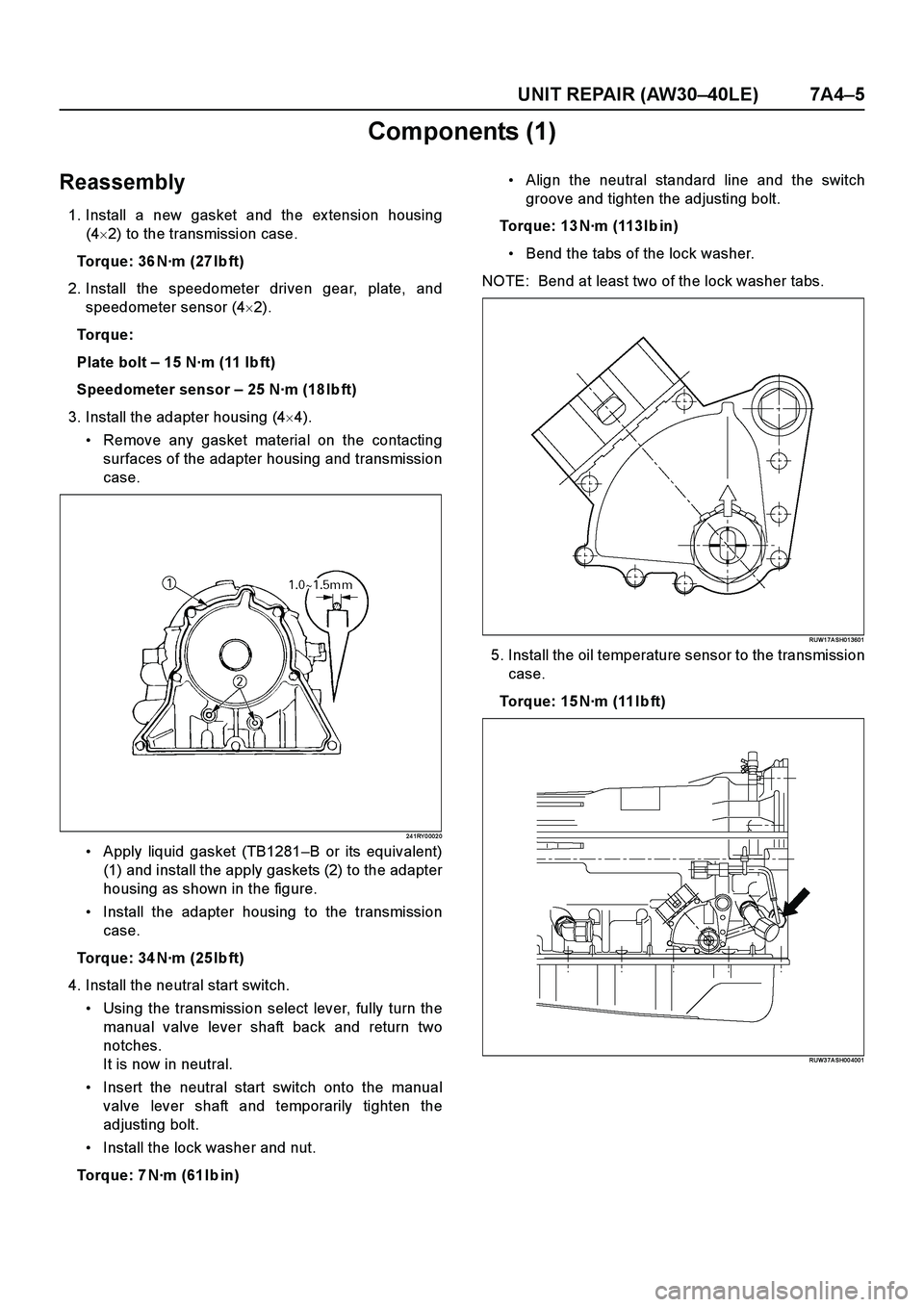
5. Remove the middle exhaust pipe.
RTW37ASH0001
6. Disconnect the transfer harness connectors and the
clips.(4WD only)
Speed sensor
2W-4W shift actuator
NOTE: Avoid turning the vehicle ignition switch to the
ON position when the 2WD-4WD connector is removed
(battery connected).
If the ignition switch must be turned to the ON position,
the controller must first be removed (memory must be
cleared because the CHECK 4WD INDICATOR will
light).
7. Support transfer case with a transmission jack.(4WD only)
8. Remove the transfer case assembly from the
transmission.(4WD only)
9. Disconnect the shift cable.
10. Remove the fuel pipe clips with the fuel pipes from the brackets and put aside it. Remove the fuel pipe
brakets from the transmission.
P1010010
11. Discinnect the transmission harness connectors
and clips.
12. Remove the oil level gauge and the guide tube.
13. Remove the suspension crossmember.
Page 3805 of 4264
ON-VEHICLE SERVICE (AW30 –40LE) 7A3-49
Tighten transmission transfer bolts as shown in
the figure.(4WD only)
261R300002
20. Connect transfer harness connectors and
clips.(4WD only)
Speed sensor
2W-4W shift actuator
21. Install the middle exhaust pipe.
RTW37ASH0001
22. Install the rear propeller shaft.
Torque: 63 N �
��
�
m (6.4 kg �
��
�
m/46 lb ft)
NOTE: Align alignment marks on the flange.
23. Install the center bearing on crossmember.
Torque: 69 N �
��
�
m (7.0 kg �
��
�
m/51 lb ft)
24.Install the front propeller shaft.(4WD only)
Torque: 63 N �
��
�
m (6.4 kg �
��
�
m/46 lb ft)
NOTE: Align alignment marks on the flange.
401RS023
25. Connect battery ground cable.
Page 3811 of 4264
UNIT REPAIR (AW30–40LE) 7A4–3
Major Components (1)
Major Components (1) and Associated parts
RTW 37A M F00 0601
E nd O FCallo ut
Disassembly steps
1. Remove the torque converter.
2. Remov e the select lev er.
Legend
(1) Torque converter
(2) Select lever
(3) Neutral start switch (Mode switch)
(4) Elbow
(5) Oil temperature sensor
(6) Breather hose
(7) Input revolution sensor(8) Output revolution sensor (4�4)
(9) Output revolution sensor (4�2)
(10) Speedometer sensor, speedometer driven gear
and plate (4�2)
(11) Extension housing (4�2)
(12) Adapter housing (4�4)
(13) Transmission assembly
Page 3812 of 4264
7A4–4 UNIT REPAIR (AW30–40LE)
3. Remove the neutral start switch (Mode switch).
Unstake the lock washer.
Remove the nut and bolt, and then remove the
neutral start switch.
Remove the lock washer.
RTW 37BSH00 010 1
4. Remove the two elbows from transmission case.
24 0RY 0 000 1
5. Remove the oil temperature sensor.
6. Remove the breather hose.
7. Remove the Input revolution sensor.
8. Remove the output revolution sensor (4�4).
9. Remove the output revolution sensor (4�2).
10. Remove the speedometer sensor, speedometer
driven gear and plate (4�2).
11. Remove the ex tension housing (4�2).
12. Remove the adapter housing (4�4).13. Remove the transmission assembly.
Install special tool to the transmission unit.
Holding fix ture: J–37227
Holding fix ture base: J–3289–20
RUW3 7A SH00 3001
Page 3813 of 4264

UNIT REPAIR (AW30–40LE) 7A4–5
Components (1)
Reassembly
1. Install a new gasket and the ex tension housing
(4�2) to the transmission case.
Torque: 36 N·m (27 Ib ft)
2. Install the speedometer driven gear, plate, and
speedometer sensor (4�2).
To r q u e :
Plate bolt – 15 N·m (11 Ib ft)
Speedometer sensor – 25 N·m (18 Ib ft)
3. Install the adapter housing (4�4).
Remove any gasket material on the contacting
surfaces of the adapter housing and transmission
case.
24 1RY 0 002 0
Apply liquid gasket (TB1281–B or its equivalent)
(1) and install the apply gaskets (2) to the adapter
housing as shown in the figure.
Install the adapter housing to the transmission
case.
Torque: 34 N·m (25 Ib ft)
4. Install the neutral start switch.
Using the transmission select lever, fully turn the
manual valve lever shaft back and return two
notches.
It is now in neutral.
Insert the neutral start switch onto the manual
valve lever shaft and temporarily tighten the
adjusting bolt.
Install the lock washer and nut.
Torque: 7 N·m (61 Ib in)Align the neutral standard line and the switch
groove and tighten the adjusting bolt.
Torque: 13 N·m (113 Ib in)
Bend the tabs of the lock washer.
NOTE: Bend at least two of the lock washer tabs.
RUW1 7A SH01 3601
5. Install the oil temperature sensor to the transmission
case.
Torque: 15 N·m (11 Ib ft)
RUW3 7A SH00 4001
Page 3814 of 4264
7A4–6 UNIT REPAIR (AW30–40LE)
6. Install the elbow.
Coat new O-rings with ATF, install them to the two
elbows.
Install the two elbows as shown in the figure.
Torque: 29 N·m (3.0kg·m/22 Ib ft)
RTW 37BSH00 060 1
7. Install the select lever.
8. Install the output revolution sensor (4�2).
9. Install the output revolution sensor (4�4).
10. Install the input revolution sensor.
11. Install the breather hose.
12. Install the torque converter.
Using calipers and a straightedge, measure the
distance from the installed surface of the
transmission housing to top of the torque converter
nut.
Correct distance: 13.5 mm (0.53 in)
24 0RY 0 000 5
Page 3815 of 4264
UNIT REPAIR (AW30–40LE) 7A4–7
Major Components (2)
Major Componets (2) and Associated Parts
RT W37 A LF00 0801
E nd O FCallo ut
Legend
(1) Converter housing
(2) Oil pan
(3) Oil strainer assembly
(4) Valve body
(5) Check valve, spring
(6) Spring
(7) Accumulator piston (B–2)
(8) Accumulator piston (C–2)(9) Accumulator piston (B–0)
(10) Accumulator piston (C–0)
(11) Second brake drum gasket
(12) Solenoid wiring
(13) Snap ring, rotor, key (4�4)
(14) Snap ring, speedometer sensor drive gear, ball
(4�2)
(15) Spacer, rotor, key, snap ring (4�2)
Page 3818 of 4264
7A4–10 UNIT REPAIR (AW30–40LE)
8. Remove the accumulator piston (B–2).
9. Remove the accumulator piston (C–2).
Remove accumulator pistons and springs from
transmission case.
24 0RY 0 001 0
10. Applying compressed air to the oil hole, remove the
B–0 accumulator piston and spring.
24 0RY 0 0011
11. Remove the C–0 accumulator piston.
24 0RY 0 0012
12. Remove the second brake drum gasket.
13. Remove the solenoid wiring.
Turn over transmission, remove the solenoid
wiring stopper plate from the case.
Pull the wiring out of the transmission case.
14. Remove the snap ring, rotor and key (4�4).
Remove the snap ring from the output shaft.
Remove the rotor and key.
2 47R20 0002
15. Remove the snap ring, speedometer sensor drive
gear and ball (4�2).
Remove the snap ring from the output shaft.
Remove the speedometer sensor drive gear, and
ball.