Page 4031 of 4264
DIAGNOSIS (JR405E) 7A2-39
Engine Speed Sensor Reference Wave Form
Measurement Terminal: A7 (+) B5(-)
Measurement Scale: 5V/div 10ms/div
Measurement Condition: At engine speed 2000rpm
0V
Page 4032 of 4264
7A2-40 DIAGNOSIS (JR405E)
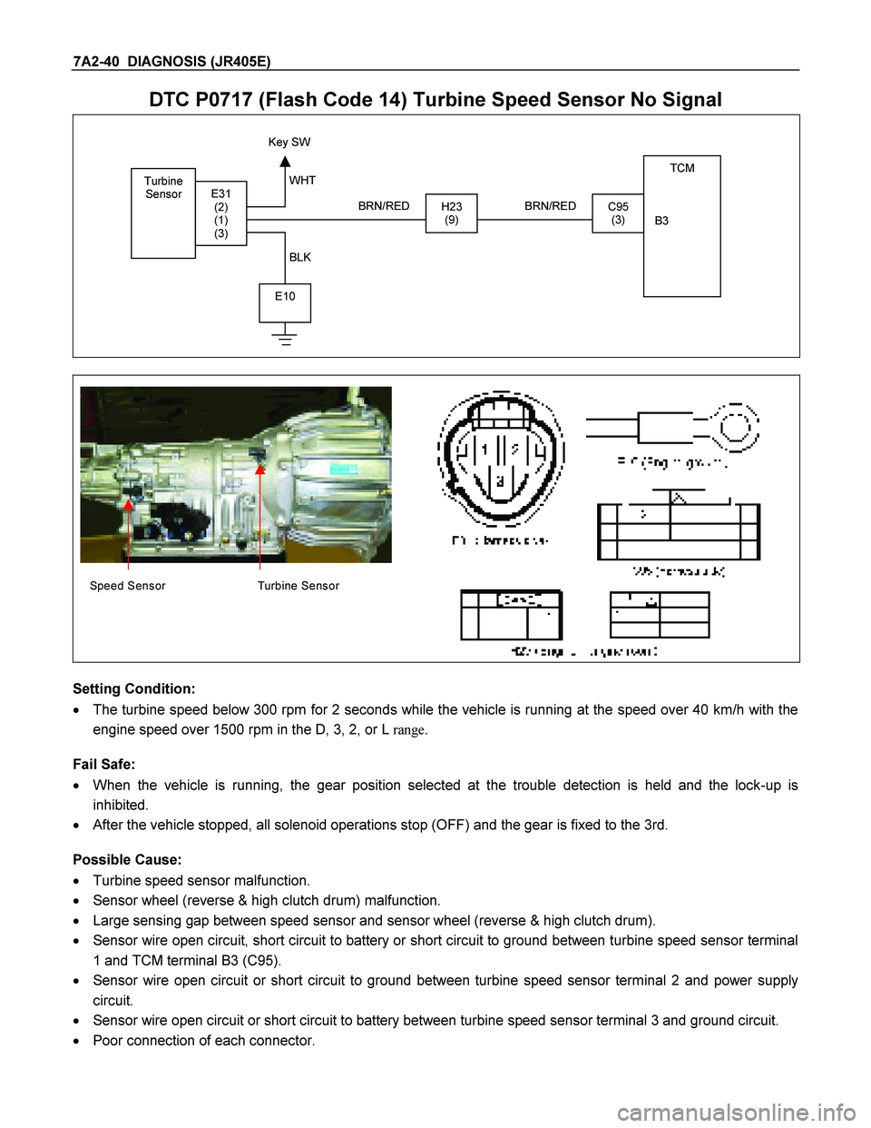
DTC P0717 (Flash Code 14) Turbine Speed Sensor No Signal
Turbine
Sensor TCM
B3
H23 (9)C95 (3) E31 (2)
(1)
(3)
E10
Key SW
BRN/RED
WHT
BLK BRN/RED
Speed Sensor Turbine Sensor
Setting Condition:
� The turbine speed below 300 rpm for 2 seconds while the vehicle is running at the speed over 40 km/h with the
engine speed over 1500 rpm in the D, 3, 2, or L range.
Fail Safe:
� When the vehicle is running, the gear position selected at the trouble detection is held and the lock-up is
inhibited.
� After the vehicle stopped, all solenoid operations stop (OFF) and the gear is fixed to the 3rd.
Possible Cause:
� Turbine speed sensor malfunction.
� Sensor wheel (reverse & high clutch drum) malfunction.
� Large sensing gap between speed sensor and sensor wheel (reverse & high clutch drum).
� Sensor wire open circuit, short circuit to battery or short circuit to ground between turbine speed sensor terminal
1 and TCM terminal B3 (C95).
� Sensor wire open circuit or short circuit to ground between turbine speed sensor terminal 2 and power supply
circuit.
� Sensor wire open circuit or short circuit to battery between turbine speed sensor terminal 3 and ground circuit.
� Poor connection of each connector.
Page 4033 of 4264
DIAGNOSIS (JR405E) 7A2-41
Reference:
When the vehicle speed 20km/h at L range in 1st gear, following signal is outputted.
Measurement terminal: B3 (C95) and B5 (C95)
-AC range by circuit tester: Approximately 6.5 V
-Oscilloscope: Following wave form can be found.
Turbine Sensor Reference Wave Form
Measurement Terminal: B3 (+) B5 (-)
Measurement Scale: 5V/div 500 micro sec/div
Measurement Condition: Vehicle speed 20km/h at L range in 1st gear
0V
Page 4034 of 4264
7A2-42 DIAGNOSIS (JR405E)
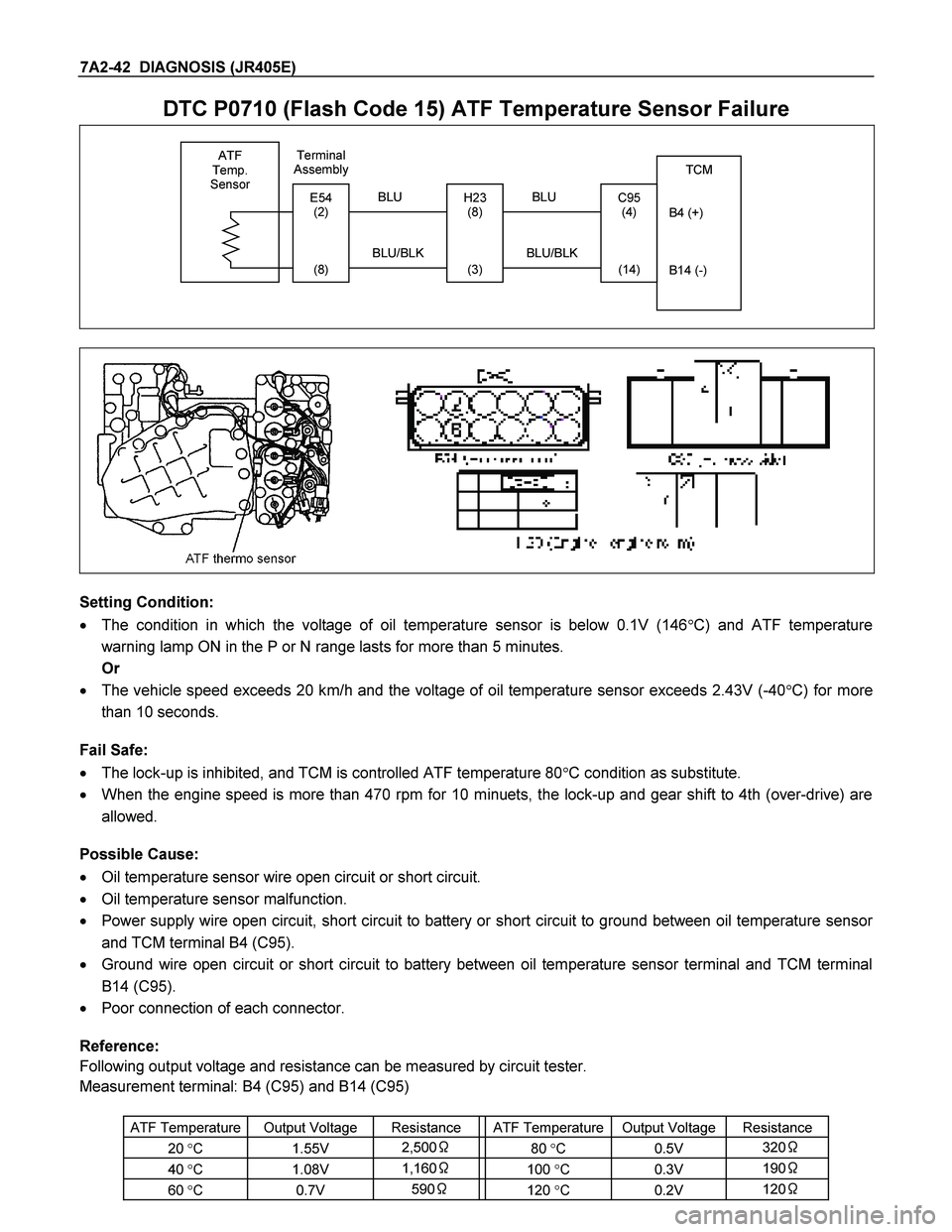
DTC P0710 (Flash Code 15) ATF Temperature Sensor Failure
ATF
Temp.
Sensor
TCM
B4 (+)
B14 (-)
H23 (8)
(3)
C95 (4)
(14)
BLU
Terminal
Assembly
BLU/BLKE54 (2)
(8)
BLU
BLU/BLK
Setting Condition:
� The condition in which the voltage of oil temperature sensor is below 0.1V (146 �C) and ATF temperature
warning lamp ON in the P or N range lasts for more than 5 minutes.
Or
� The vehicle speed exceeds 20 km/h and the voltage of oil temperature sensor exceeds 2.43V (-40 �C) for more
than 10 seconds.
Fail Safe:
� The lock-up is inhibited, and TCM is controlled ATF temperature 80 �C condition as substitute.
� When the engine speed is more than 470 rpm for 10 minuets, the lock-up and gear shift to 4th (over-drive) are
allowed.
Possible Cause:
� Oil temperature sensor wire open circuit or short circuit.
� Oil temperature sensor malfunction.
� Power supply wire open circuit, short circuit to battery or short circuit to ground between oil temperature sensor
and TCM terminal B4 (C95).
� Ground wire open circuit or short circuit to battery between oil temperature sensor terminal and TCM terminal
B14 (C95).
� Poor connection of each connector.
Reference:
Following output voltage and resistance can be measured by circuit tester.
Measurement terminal: B4 (C95) and B14 (C95)
ATF Temperature Output Voltage Resistance ATF Temperature Output Voltage Resistance
20 �C �1.55V 2,500 � 80 �C �0.5V 320 �
40 �C 1.08V 1,160 � 100 �C �0.3V 190 �
60 �C �0.7V 590 � 120 �C �0.2V 120 �
Page 4038 of 4264
7A2-46 DIAGNOSIS (JR405E)
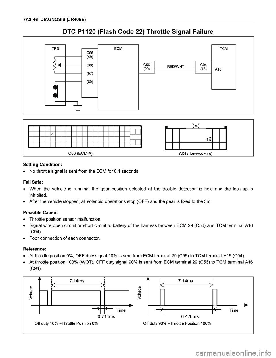
DTC P1120 (Flash Code 22) Throttle Signal Failure
TPS TCM
A16
C56 (29)C94 (16)
RED/WHT
C56
(49)
(38)
(57)
(69)
ECM
C56 (ECM-A)
Setting Condition:
� No throttle signal is sent from the ECM for 0.4 seconds.
Fail Safe:
� When the vehicle is running, the gear position selected at the trouble detection is held and the lock-up is
inhibited.
� After the vehicle stopped, all solenoid operations stop (OFF) and the gear is fixed to the 3rd.
Possible Cause:
� Throttle position sensor malfunction.
� Signal wire open circuit or short circuit to battery of the harness between ECM 29 (C56) and TCM terminal A16
(C94).
� Poor connection of each connector.
Reference:
� At throttle position 0%, OFF duty signal 10% is sent from ECM terminal 29 (C56) to TCM terminal A16 (C94).
� At throttle position 100% (WOT), OFF duty signal 90% is sent from ECM terminal 29 (C56) to TCM terminal A16
(C94).
7.14ms 7.14ms
Time Time
0.714ms 6.426ms
Vo l t a ge
Off duty 10% =Throttle Position 0%
Vo l t a ge
Off duty 90% =Throttle Position 100%
Page 4068 of 4264
7A2-76 DIAGNOSIS (JR405E)
DTC P0731 (Flash Code 41) 1st Gear Ratio Error
DTC P0732 (Flash Code 42) 2nd Gear Ratio Error
DTC P0733 (Flash Code 43) 3rd Gear Ratio Error
DTC P0734 (Flash Code 44) 4th Gear Ratio Error
Pre-setting Condition:
� No other DTCs.
� 2 seconds elapsed after D, 3, 2, or 1 range was selected.
� Vehicle is running at the vehicle speed over 10 km/h with the turbine speed over 1000 rpm.
� Except at the gear shifting.
� ATF temperature more than 60�C.
� No fail safe valve malfunction.
Setting Condition:
In the case pre-setting conditions are met, the TCM calculates the turbine speed that corresponds to the gear ratio
of the outputted solenoid pattern in about 7 seconds after each gear shift has completed, and when the output shaft
speed against the turbine speed exceeds 500 rpm.
Fail Safe:
� No fail safe function
Possible Cause:
� Turbine sensor or speed sensor malfunction.
� Shift solenoid malfunction.
� Clutch slipping.
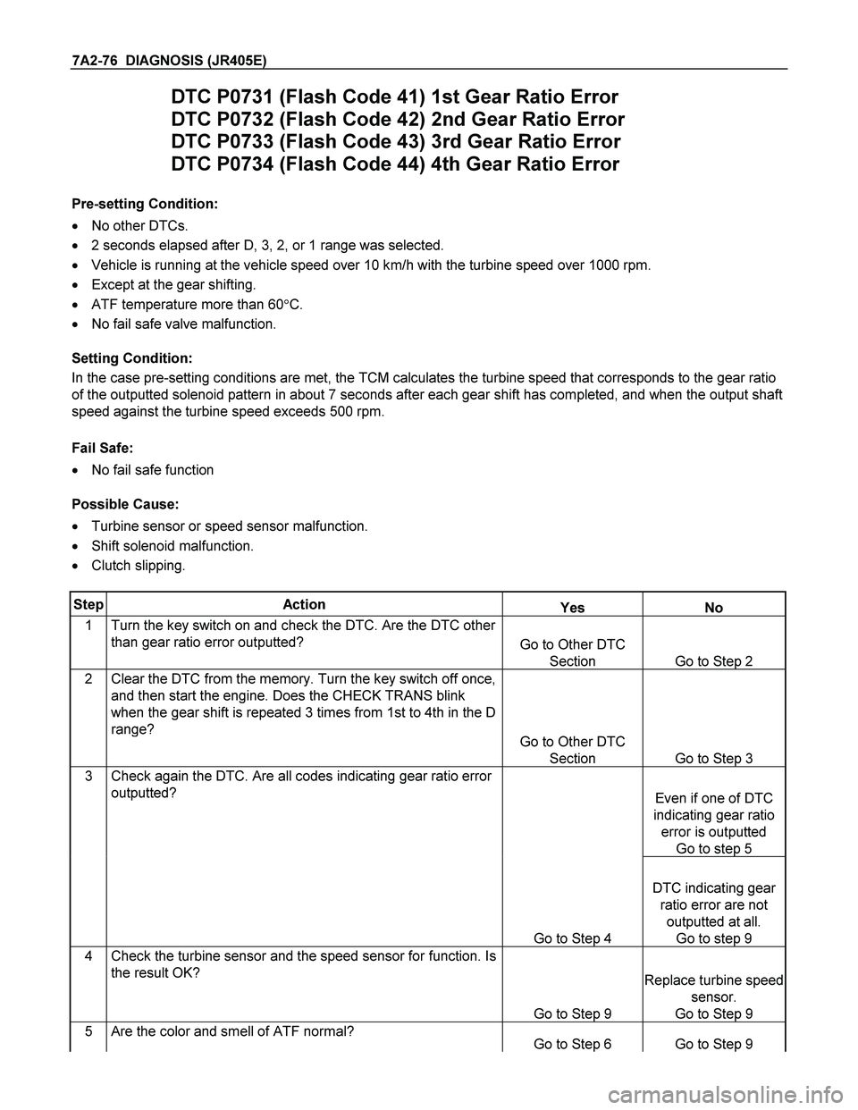
Step Action Yes No
1 Turn the key switch on and check the DTC. Are the DTC other
than gear ratio error outputted? Go to Other DTC
Section Go to Step 2
2 Clear the DTC from the memory. Turn the key switch off once,
and then start the engine. Does the CHECK TRANS blink
when the gear shift is repeated 3 times from 1st to 4th in the D
range? Go to Other DTC
Section Go to Step 3
3 Check again the DTC. Are all codes indicating gear ratio error
outputted?
Even if one of DTC
indicating gear ratio
error is outputted
Go to step 5
Go to Step 4
DTC indicating gear
ratio error are not
outputted at all.
Go to step 9
4 Check the turbine sensor and the speed sensor for function. Is
the result OK?
Go to Step 9
Replace turbine speed
sensor.
Go to Step 9
5 Are the color and smell of ATF normal? Go to Step 6 Go to Step 9
Page 4085 of 4264
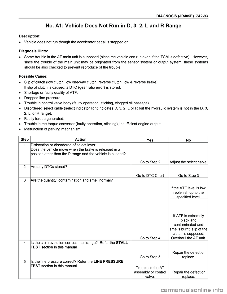
DIAGNOSIS (JR405E) 7A2-93
No. A1: Vehicle Does Not Run in D, 3, 2, L and R Range
Description:
� Vehicle does not run though the accelerator pedal is stepped on.
Diagnosis Hints:
� Some trouble in the AT main unit is supposed (since the vehicle can run even if the TCM is defective). However,
since the trouble of the main unit may be originated from the sensor system or output system, these systems
should be also checked to prevent reproduce of the trouble.
Possible Cause:
� Slip of clutch (low clutch, low one-way clutch, reverse clutch, low & reverse brake).
If slip of clutch is caused, a DTC (gear ratio error) is stored.
� Shortage or faulty quality of ATF.
� Dropped line pressure.
� Trouble in control valve body (faulty operation, sticking, clogged oil passage).
� Disordered select cable (select indicator light indicates D, 3, 2, L or R but the hydraulic system is not in the D, 3,
2, L, or R range).
� Faulty torque generated.
� Trouble in the torque converter (faulty operation, sticking), insufficient engine output.
� Malfunction of parking mechanism.
Step Action Yes No
1 Dislocation or disordered of select lever.
Does the vehicle move when the brake is released in a
position other than the P range and the vehicle is pushed?
Go to Step 2
Adjust the select cable.
2 Are any DTCs stored?
Go to DTC Chart Go to Step 3
3 Are the quantity, contamination and smell normal?
If the ATF level is low,
replenish up to the
specified level.
Go to Step 4
If ATF is extremely
black and
contaminated and
smells burnt, slip of the
clutch is supposed.
Overhaul the AT unit.
4 Is the stall revolution correct in all range? Refer the STALL
TEST section in this manual.
Go to Step 5
Repair the defect or
replace.
5 Is the line pressure correct? Refer the LINE PRESSURE
TEST section in this manual. Trouble in the AT
assembly or control
valve.
Repair the defect or
replace.
Page 4086 of 4264
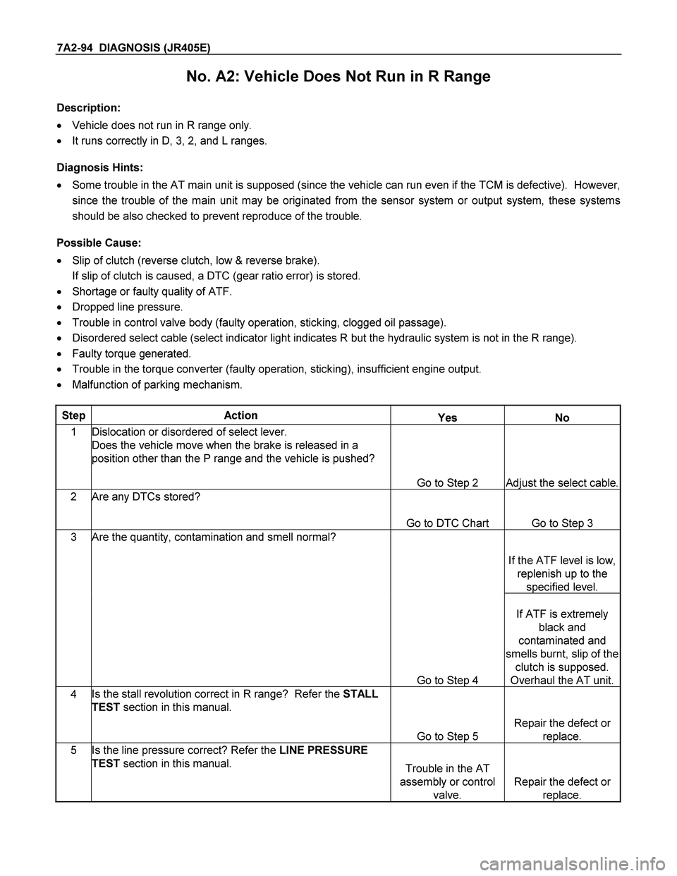
7A2-94 DIAGNOSIS (JR405E)
No. A2: Vehicle Does Not Run in R Range
Description:
� Vehicle does not run in R range only.
� It runs correctly in D, 3, 2, and L ranges.
Diagnosis Hints:
� Some trouble in the AT main unit is supposed (since the vehicle can run even if the TCM is defective). However,
since the trouble of the main unit may be originated from the sensor system or output system, these systems
should be also checked to prevent reproduce of the trouble.
Possible Cause:
� Slip of clutch (reverse clutch, low & reverse brake).
If slip of clutch is caused, a DTC (gear ratio error) is stored.
� Shortage or faulty quality of ATF.
� Dropped line pressure.
� Trouble in control valve body (faulty operation, sticking, clogged oil passage).
� Disordered select cable (select indicator light indicates R but the hydraulic system is not in the R range).
� Faulty torque generated.
� Trouble in the torque converter (faulty operation, sticking), insufficient engine output.
� Malfunction of parking mechanism.
Step Action Yes No
1 Dislocation or disordered of select lever.
Does the vehicle move when the brake is released in a
position other than the P range and the vehicle is pushed?
Go to Step 2
Adjust the select cable.
2 Are any DTCs stored?
Go to DTC Chart Go to Step 3
3 Are the quantity, contamination and smell normal?
If the ATF level is low,
replenish up to the
specified level.
Go to Step 4
If ATF is extremely
black and
contaminated and
smells burnt, slip of the
clutch is supposed.
Overhaul the AT unit.
4 Is the stall revolution correct in R range? Refer the STALL
TEST section in this manual.
Go to Step 5
Repair the defect or
replace.
5 Is the line pressure correct? Refer the LINE PRESSURE
TEST section in this manual. Trouble in the AT
assembly or control
valve.
Repair the defect or
replace.