Page 3819 of 4264
UNIT REPAIR (AW30–40LE) 7A4–11
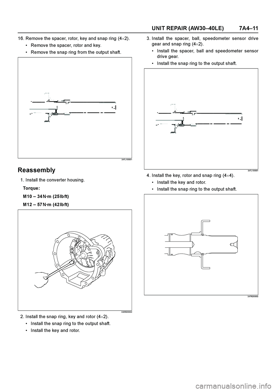
16. Remove the spacer, rotor, key and snap ring (4�2).
Remove the spacer, rotor and key.
Remove the snap ring from the output shaft.
2 47L10 000 1
Reassembly
1. Install the converter housing.
To r q u e :
M10 – 34 N·m (25 lb ft)
M12 – 57 N·m (42 lb ft)
2 40R20 002 2
2. Install the snap ring, key and rotor (4�2).
Install the snap ring to the output shaft.
Install the key and rotor.3. Install the spacer, ball, speedometer sensor drive
gear and snap ring (4�2).
Install the spacer, ball and speedometer sensor
drive gear.
Install the snap ring to the output shaft.
24 7L10 0001
4. Install the key, rotor and snap ring (4�4).
Install the key and rotor.
Install the snap ring to the output shaft.
2 47R20 0002
Page 3947 of 4264

CONSTRUCTION AND FUNCTION 7A1-1
SECTION 7A1
CONSTRUCTION AND FUNCTION
TABLE OF CONTENTS
PAGE
DESCRIPTION ..............................................................................................................................7A1- 3
CONSTRUCTION ....................................................................................................................7A1- 3
MAIN DATA AND SPECIFICATION .....................................................................................7A1- 4
NUMBER PLATE LOCATION ...............................................................................................7A1- 5
ELECTRONIC CONTROL COMPONENTS LOCATION ..................................................7A1- 6
TRANSMISSION CONTROL UNIT (TCM) PERIPHERAL CIRCUIT ..............................7A1- 7
STRUCTURE AND FUNCTION OF COMPONENT ...........................................................7A1- 8
TORQUE CONVERTER (WITH LOCK-UP FUNCTION) ..................................................7A1- 8
OIL PUMP .................................................................................................................................7A1- 9
INPUT SHAFT ..........................................................................................................................7A1- 10
OUTPUT SHAFT ......................................................................................................................7A1- 10
GEAR SHIFTING MECHANISM ............................................................................................7A1- 10
CONTROL VALVE ...................................................................................................................7A1- 14
OIL PASSAGE .........................................................................................................................7A1- 19
PARKING FUNCTION .............................................................................................................7A1- 20
INHIBITOR SWITCH ...............................................................................................................7A1- 21
TURBINE SENSOR .................................................................................................................7A1- 22
SPEED SENSOR .....................................................................................................................7A1- 22
THROTTLE POSITION SENSOR (TPS) .............................................................................7A1- 23
ENGINE SPEED SENSOR (=TDC SENSOR) ....................................................................7A1- 23
BRAKE SWITCH ......................................................................................................................7A1- 24
MODE SELECT SWITCH .......................................................................................................7A1- 24
TRANSMISSION CONTROL MODULE (TCM) ..................................................................7A1- 25
CONTROL MECHANISM ............................................................................................................7A1- 26
CONTENT OF FUNCTION AND CONTROL ......................................................................7A1- 26
CONTROL ITEM, INPUT AND OUTPUT .................................................................... 7A1- 29
LINE PRESSURE CONTROL ..................................................................................... 7A1- 30
Page 3949 of 4264

CONSTRUCTION AND FUNCTION 7A1-3
DESCRIPTION
CONSTRUCTION
1 Converter Housing 6 Low Clutch 11 Oil Pump
2 Torque Converter 7 Low & Reverse Brake 12 Control Valve
3 High Clutch 8 Output Shaft 13 Low One-way Clutch
4 Reverse Clutch 9 Extension Housing 14 Parking Gear
5 2-4 Brake 10 Input Shaft
Figure 1. Construction of Automatic Transmission
The JR405E automatic transmission is electrically controlled by a microcomputer transmission control module
(TCM). There are four forward speeds and one reverse speed.
This JR405E automatic transmission employs a clutch pressure direct control system (Direct Electronic Shift
Control: DESC) using a duty cycle type solenoid, which ensures high shift quality.
This transmission also controls learning and constantly checks the time of each clutch and brake required for
the speed change to match this time with the target value for the optimum speed change.
The TCM will automatically select the most appropriate shift points and lock-up points depending on the
throttle opening angle, the vehicle speed and the vehicle load.
If any trouble arises in the vehicle sensor, throttle sensor, solenoid, etc., the fail-safe control function is
activated to keep the running performance.
Problems with the sensors, the solenoids can be quickly detected with the self diagnosis procedure described
in this manual.
The JR405E automatic transmission consists of the torque converter, the oil pump, the input shaft, the out put
shaft, the planetary gears and the control valve.
The gear train consists of two planetary gear sets and three multiple plate clutches in combination with two
multiple plate brakes and a one-way clutch.
2WD
4WD
Page 3952 of 4264
7A1-6 CONSTRUCTION AND FUNCTION
ELECTRONIC CONTROL COMPONENTS LOCATION
4WD Only 4WD Only
Instrument panel (Meter)
Speed meter (2WD Only)
Shift position indicator lamp
POWER DRIVE, 3rd START
indicator lamp
A/T OIL TEMP indicator lamp
CHECK TRANS indicator lam
p
Brake pedal
Brake Switch
Select lever
Power Drive
, 3rd Start select switch
Transmission Control Module (TCM)
Electrical source
Ignition
Battery voltage
Speed sensor
Turbine sensor
Inhibitor switch
ATF thermo sensor
High clutch oil pressure switch
2-4 brake oil pressure switch
Low & Reverse brake oil pressure
switch
Line pressure solenoid
Low clutch solenoid
High clutch solenoid
2-4 brake solenoid
Low & Reverse brake solenoid
Lock-up solenoid
Transmission
Transfer Control Module
Transfer
4L mode switch
Engine
Engine speed sensor
Throttle Position Sensor
Engine Control Module (ECM)
Data link connector
Page 3960 of 4264
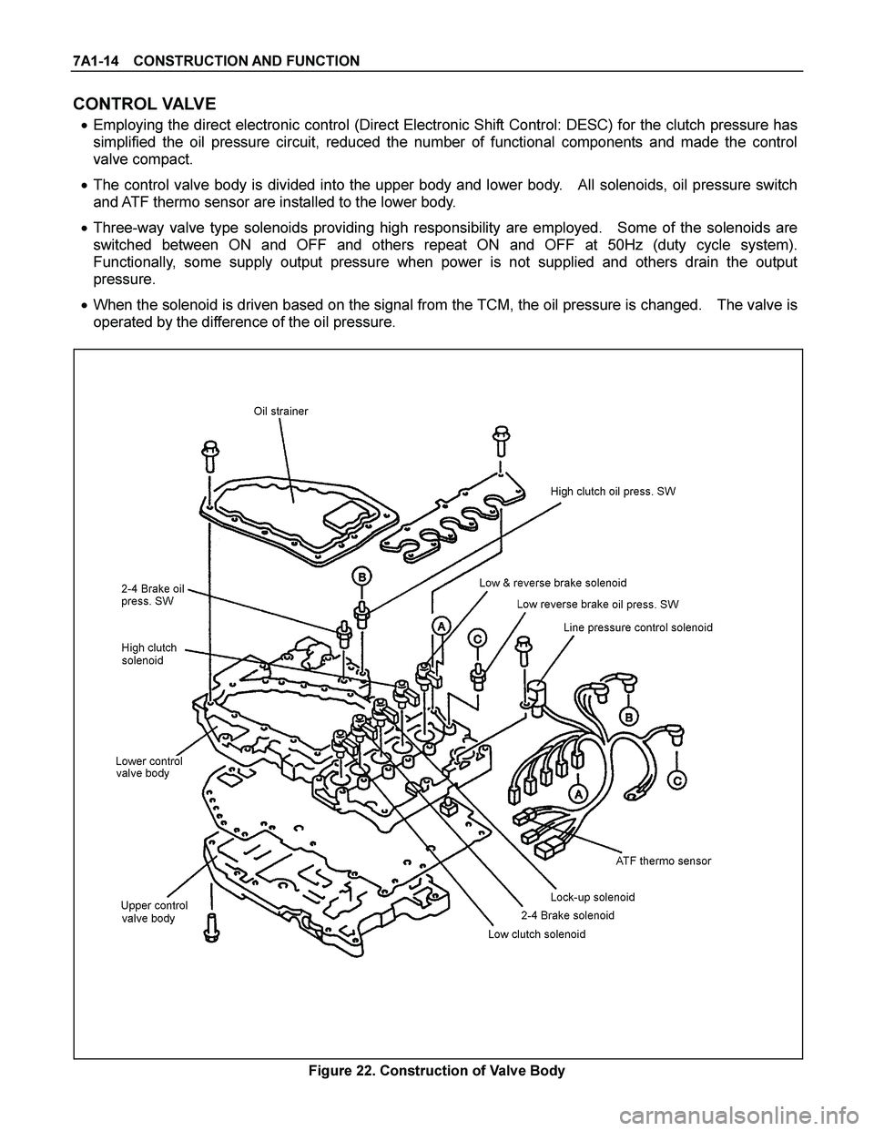
7A1-14 CONSTRUCTION AND FUNCTION
CONTROL VALVE
� Employing the direct electronic control (Direct Electronic Shift Control: DESC) for the clutch pressure has
simplified the oil pressure circuit, reduced the number of functional components and made the control
valve compact.
� The control valve body is divided into the upper body and lower body. All solenoids, oil pressure switch
and ATF thermo sensor are installed to the lower body.
� Three-way valve type solenoids providing high responsibility are employed. Some of the solenoids are
switched between ON and OFF and others repeat ON and OFF at 50Hz (duty cycle system).
Functionally, some supply output pressure when power is not supplied and others drain the output
pressure.
� When the solenoid is driven based on the signal from the TCM, the oil pressure is changed. The valve is
operated by the difference of the oil pressure.
Figure 22. Construction of Valve Body
Page 3963 of 4264

CONSTRUCTION AND FUNCTION 7A1-17
ATF Thermo Sensor
� The ATF thermo sensor detects the ATF temperature in the oil pan and sends signal to the TCM.
� The ATF thermo sensor is of the thermister type that the resistance value changes according to the ATF
oil temperature.
� The lower is the ATF temperature, the larger is the resistance, and vice versa.
� When the ATF temperature exceeds 145�C, the TCM lights up the ATF temperature warning lamp in the
meter. When the ATF temperature decreases below 128�C, the ATF temperature warning lamp goes out.
� The ATF thermo sensor is installed to the lower control valve body and integrated with the harness
assembly.
10.0 100.0 1,000.0 10,000.0 100,000.0
-30 -20 -10 0 10 20 30 40 50 60 70 80 90 100 110 120 130 140 150 160
A TF Temperature (°C)
Resistance (�
)
Figure 29. Characteristic of Thermo Sensor
Figure 30. Location of Thermo Sensor
ATF Temperature
(deg. C) Resistance (Ohm)
(Approximately) ATF Temperature
(deg. C) Resistance (Ohm)
(Approximately)
-30 29,614 100 190
-20 16,705 110 149
-10 9,842 120 118
0 6,028 128 98
20 2,500 130 94
40 1,160 135 84
50 819 140 76
60 591 145 68
80 324 150 62
Page 3964 of 4264
7A1-18 CONSTRUCTION AND FUNCTION
Terminal Assembly
Pin No. Connected to Connected TCMPin No.
6 Line Pressure Solenoid B23
12 Low & Reverse Brake Oil Pressure Switch B12
5 Low & Reverse Brake Duty Solenoid B6
11 Ground Return B22
4 Lock-up Duty Solenoid B17
10 High Clutch Duty Solenoid B8
3 Low Clutch Duty Solenoid B9
9 2-4 Brake Duty Solenoid B7
2 Oil Thermo Sensor B4
8 Oil Thermo Sensor Ground B14
1 High Clutch Oil Pressure Switch B20
7 2-4 Brake Oil Pressure Switch B1
123456
891011127
Terminal Assembly Inhibitor Switch
Figure 31. Pin Assignment Figure 32. Location of Terminal Assembly
Page 3968 of 4264
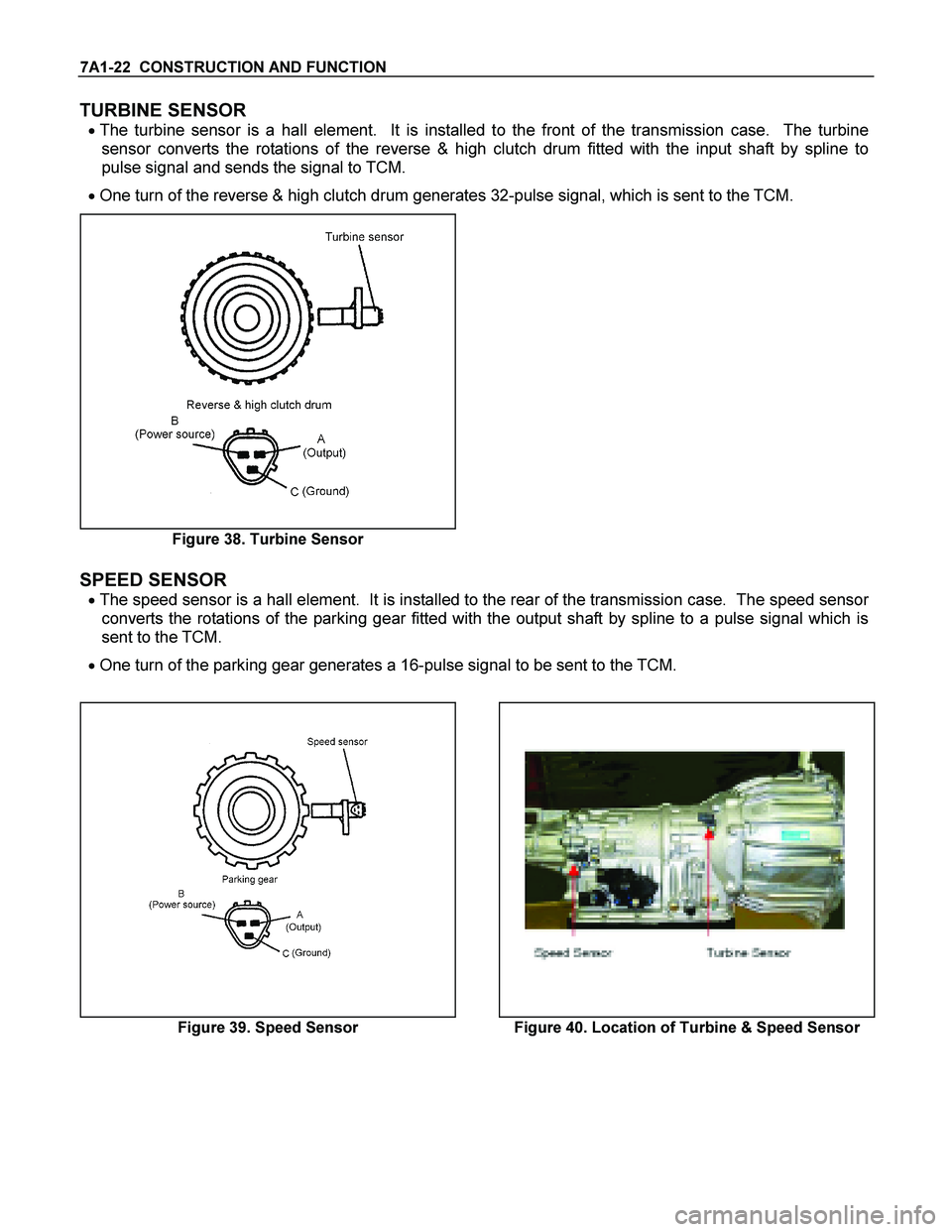
7A1-22 CONSTRUCTION AND FUNCTION
TURBINE SENSOR
� The turbine sensor is a hall element. It is installed to the front of the transmission case. The turbine
sensor converts the rotations of the reverse & high clutch drum fitted with the input shaft by spline to
pulse signal and sends the signal to TCM.
� One turn of the reverse & high clutch drum generates 32-pulse signal, which is sent to the TCM.
Figure 38. Turbine Sensor
SPEED SENSOR
� The speed sensor is a hall element. It is installed to the rear of the transmission case. The speed sensor
converts the rotations of the parking gear fitted with the output shaft by spline to a pulse signal which is
sent to the TCM.
� One turn of the parking gear generates a 16-pulse signal to be sent to the TCM.
Figure 39. Speed Sensor Figure 40. Location of Turbine & Speed Sensor

Speed meter (2WD Only)
Shift position indicator lamp
POW")