Page 4004 of 4264

7A2-12 DIAGNOSIS (JR405E)
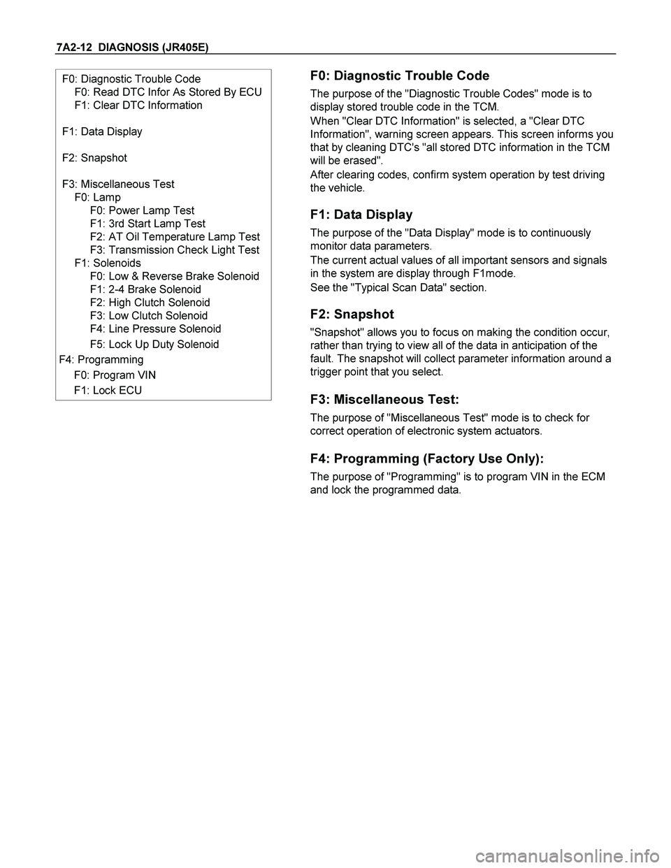
F0: Diagnostic Trouble Code
F0: Read DTC Infor As Stored By ECU
F1: Clear DTC Information
F1: Data Display
F2: Snapshot
F3: Miscellaneous Test
F0: Lamp
F0: Power Lamp Test
F1: 3rd Start Lamp Test
F2: AT Oil Temperature Lamp Test
F3: Transmission Check Light Test
F1: Solenoids
F0: Low & Reverse Brake Solenoid
F1: 2-4 Brake Solenoid
F2: High Clutch Solenoid
F3: Low Clutch Solenoid
F4: Line Pressure Solenoid
F5: Lock Up Duty Solenoid
F4: Programming
F0: Program VIN
F1: Lock ECU
F0: Diagnostic Trouble Code
The purpose of the "Diagnostic Trouble Codes" mode is to
display stored trouble code in the TCM.
When "Clear DTC Information" is selected, a "Clear DTC
Information", warning screen appears. This screen informs you
that by cleaning DTC's "all stored DTC information in the TCM
will be erased".
After clearing codes, confirm system operation by test driving
the vehicle.
F1: Data Display
The purpose of the "Data Display" mode is to continuously
monitor data parameters.
The current actual values of all important sensors and signals
in the system are display through F1mode.
See the "Typical Scan Data" section.
F2: Snapshot
"Snapshot" allows you to focus on making the condition occur,
rather than trying to view all of the data in anticipation of the
fault. The snapshot will collect parameter information around a
trigger point that you select.
F3: Miscellaneous Test:
The purpose of "Miscellaneous Test" mode is to check for
correct operation of electronic system actuators.
F4: Programming (Factory Use Only):
The purpose of "Programming" is to program VIN in the ECM
and lock the programmed data.
Page 4008 of 4264

7A2-16 DIAGNOSIS (JR405E)
INTERMITTENT DIAGNOSIS
If the Tech 2 displays any codes as intermittent, or if after a test drive any codes does not reappear, the problem is
most likely a faulty electrical connection or loose wiring.
Terminals should always be the prime suspect.
Intermittent rarely occur in sophisticated electronic components such as the TCM.
When an intermittent problem is encountered, check suspect circuits for:
� Poor terminal to wire connection.
� Terminals not fully seated in the connector body.
� Improperly formed or damaged terminals.
� Loose, dirty or damaged terminals.
Any time you have an intermittent in more than one circuit, check whether the circuits share a common ground
connection.
� Pinched or damaged wires.
� Electric interference.
Check for improperly installed electrical options, such as light, radios, etc.
Use the F2: Snapshot mode of the Tech 2 to help isolate the cause of an intermittent fault. The snapshot mode will
record information before and after the problem occurs. Set the snapshot to "Trigger" on the suspected code or, if
you notice the reported symptom during test drive, trigger the snapshot manually.
After the snapshot has been triggered, command the Tech 2 to play back the flow of data recorded from each of the
various sensors. Sings of intermittent fault in a sensor circuit are a sudden unexplainable jump in data values out of
the normal range.
Page 4024 of 4264
7A2-32 DIAGNOSIS (JR405E)
No. Connector face No. Connector face
E-30
(4JH1-TC)
Gray A/T speed sensor H-23
(6VE1)
(4JH1-TC)
WhiteEngine ~ Engine room B
E-31
(4JH1-TC)
Gray Turbine sensor P-1
SilverBattery (+)
E-44
Gray
Vehicle speed sensor P-2
SilverRelay & Fuse box
E-51
(4JH1-TC)
Black Inhibiter switch P-5
SilverBattery (-)
E-54
(4JH1-TC)
Black A/T term ASM P-6
SilverBody earth (Ground)
H-4
(6VE1)
(4JH1-TC)
White Engine ~ Engine room P-10
SilverEngine ground
H-6
White
Engine room ~ INST R-15
Black2-4 WD control unit
H-7
White
Engine room ~ INST
H-18
(RHD)
White Engine room ~ INST
H-22
(6VE1)
(4JH1-TC)
White Engine ~ Engine room C
Page 4025 of 4264
DIAGNOSIS (JR405E) 7A2-33
DIAGNOSIS TROUBLE CODE TABLE
Flash Code
(P-Code)
CHECK TRANS Flash Pattern
Description
CHECK
TRANS
Warning
11 (P0722) Vehicle Speed Sensor No Signal ON
12 (-) Normal -
13 (P0727) ON
Engine Revolution Sensor No
Signal
14 (P0717) Turbine Speed Sensor No Signal ON
15 (P0710) ATF Temperature Sensor FailureOFF
16 (P0560) System Voltage Failure ON
17 (P0705) Inhibitor Switch Failure ON
22 (P1120) Throttle Signal Failure ON
25 (P1875) GND Return Circuit Failure ON
26 (P1853) ON
Low & Reverse Brake Pressure
Switch Failure
27 (P1858) 2-4 Brake Pressure Switch FailureON
28 (P1863) ON
High Clutch Pressure Switch
Failure
31 (P0753) ON
Low & Reverse Brake Duty
Solenoid Failure
32 (P0758) 2-4BrakeDutySolenoidFailure ON
33 (P0763) ON
High Clutch Duty Solenoid Failure
Page 4027 of 4264

DIAGNOSIS (JR405E) 7A2-35
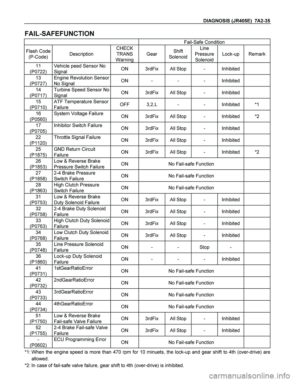
FAIL-SAFEFUNCTION
Fail-Safe Condition
Flash Code
(P-Code)
Description
CHECK
TRANS
Warning
Gear Shift
Solenoid
Line
Pressure
Solenoid
Lock-up
Remark
11
(P0722)
Vehicle peed Sensor No
Signal ON 3rdFix All Stop - Inhibited
13
(P0727)
Engine Revolution Sensor
No Signal ON - - - Inhibited
14
(P0717)
Turbine Speed Sensor No
Signal ON 3rdFix All Stop - Inhibited
15
(P0710)
ATF Temperature Sensor
Failure OFF 3,2,L - - Inhibited*1
16
(P0560)
System Voltage Failure ON 3rdFix All Stop - Inhibited*2
17
(P0705)
Inhibitor Switch Failure ON 3rdFix All Stop - Inhibited
22
(P1120)
Throttle Signal Failure ON 3rdFix All Stop - Inhibited
25
(P1875)
GND Return Circuit
Failure ON 3rdFix All Stop - Inhibited*2
26
(P1853)
Low & Reverse Brake
Pressure Switch Failure ON No Fail-safe Function
27
(P1858)
2-4 Brake Pressure
Switch Failure ON No Fail-safe Function
28
(P1863)
High Clutch Pressure
Switch Failure ON No Fail-safe Function
31
(P0753)
Low & Reverse Brake
Duty Solenoid Failure ON 3rdFix All Stop - Inhibited
32
(P0758)
2-4 Brake Duty Solenoid
Failure ON 3rdFix All Stop - Inhibited
33
(P0763)
High Clutch Duty Solenoid
Failure ON 3rdFix All Stop - Inhibited
34
(P0768)
Low Clutch Duty Solenoid
Failure ON 3rdFix All Stop - Inhibited
35
(P0748)
Line Pressure Solenoid
Failure ON - - Stop -
36
(P1860)
Lock-up Duty Solenoid
Failure ON - - - Inhibited
41
(P0731)
1stGearRatioError ON No Fail-safe Function
42
(P0732)
2ndGearRatioError ON No Fail-safe Function
43
(P0733)
3rdGearRatioError ON No Fail-safe Function
44
(P0734)
4thGearRatioError ON No Fail-safe Function
51
(P1750)
Low & Reverse Brake
Fail-safe Valve Failure ON 3rdFix All Stop - Inhibited
52
(P1755)
2-4 Brake Fail-safe Valve
Failure ON 3rdFix All Stop - Inhibited
-
(P0602)
ECU Programming Error ON No Fail-safe Function
*1: When the engine speed is more than 470 rpm for 10 minuets, the lock-up and gear shift to 4th (over-drive) are
allowed.
*2: In case of fail-safe valve failure, gear shift to 4th (over-drive) is inhibited.
Page 4028 of 4264

7A2-36 DIAGNOSIS (JR405E)
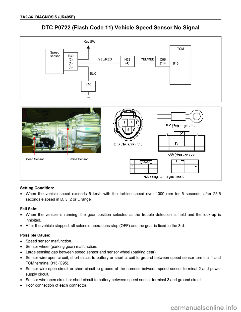
DTC P0722 (Flash Code 11) Vehicle Speed Sensor No Signal
Speed
Sensor
TCM
B13
H23
(4)C95
(13)E30
(2)
(1)
(3)
E10
Key SW
YEL/RED
BLK YEL/RED
Speed Sensor Turbine Sensor
Setting Condition:
� When the vehicle speed exceeds 5 km/h with the turbine speed over 1000 rpm for 5 seconds, after 25.5
seconds elapsed in D, 3, 2 or L range.
Fail Safe:
� When the vehicle is running, the gear position selected at the trouble detection is held and the lock-up is
inhibited.
� After the vehicle stopped, all solenoid operations stop (OFF) and the gear is fixed to the 3rd.
Possible Cause:
� Speed sensor malfunction.
� Sensor wheel (parking gear) malfunction.
� Large sensing gap between speed sensor and sensor wheel (parking gear).
� Sensor wire open circuit, short circuit to battery or short circuit to ground between speed sensor terminal 1 and
TCM terminal B13 (C95).
� Sensor wire open circuit or short circuit to ground of the harness between speed sensor terminal 2 and power
supply circuit.
� Sensor wire open circuit or short circuit to battery between speed sensor terminal 3 and ground circuit.
� Poor connection of each connector.
Page 4029 of 4264
DIAGNOSIS (JR405E) 7A2-37
Reference:
When the vehicle speed 20km/h at L range in 1st gear, following signal is outputted.
Measurement terminal: B13 (C95) and B5 (C95)
-AC range by circuit tester: Approximately 6.8 V
-Oscilloscope: Following wave form can be found.
Vehicle Speed Sensor Reference Wave Form
Measurement Terminal: B13 (+) B5 (-)
Measurement Scale: 5V/div 5ms/div
Measurement Condition: Vehicle speed 20km/h at L range in 1st gear0V
Page 4030 of 4264
7A2-38 DIAGNOSIS (JR405E)
DTC P0727 (Flash Code 13) Engine Revolution Sensor No Signal
RED
TDC
Sensor TCM
A7
C94 (7)
BLK/RED
WHT
C56
(27)
E9
(1)
(2)
(3)
C57 (98)
(90)
(101)
ECM
C56 (ECM-A)
Setting Condition:
� The engine speed becomes 0 rpm for 2 seconds while the vehicle is running at the over 40 km/h.
Fail Safe:
� Lock-up is inhibited.
Possible Cause:
� Crank position sensor malfunction.
� Sensor wheel (flywheel) malfunction.
� Large sensing gap between speed sensor and sensor wheel (flywheel).
� Faulty input signal from crank position sensor to ECM.
� Signal wire open circuit or short circuit to battery between ECM A24 and TCM terminal A7 (C94).
� Poor connection of each connector.
Reference:
When the engine speed 2000rpm, following signal is outputted.
Measurement terminal: A7 (C94) and B5 (C95)
-AC range by circuit tester: Approximately 6.2V
-Oscilloscope: Following wave form can be found.