Page 3032 of 4264
1-22 HEATER AND AIR CONDITIONING
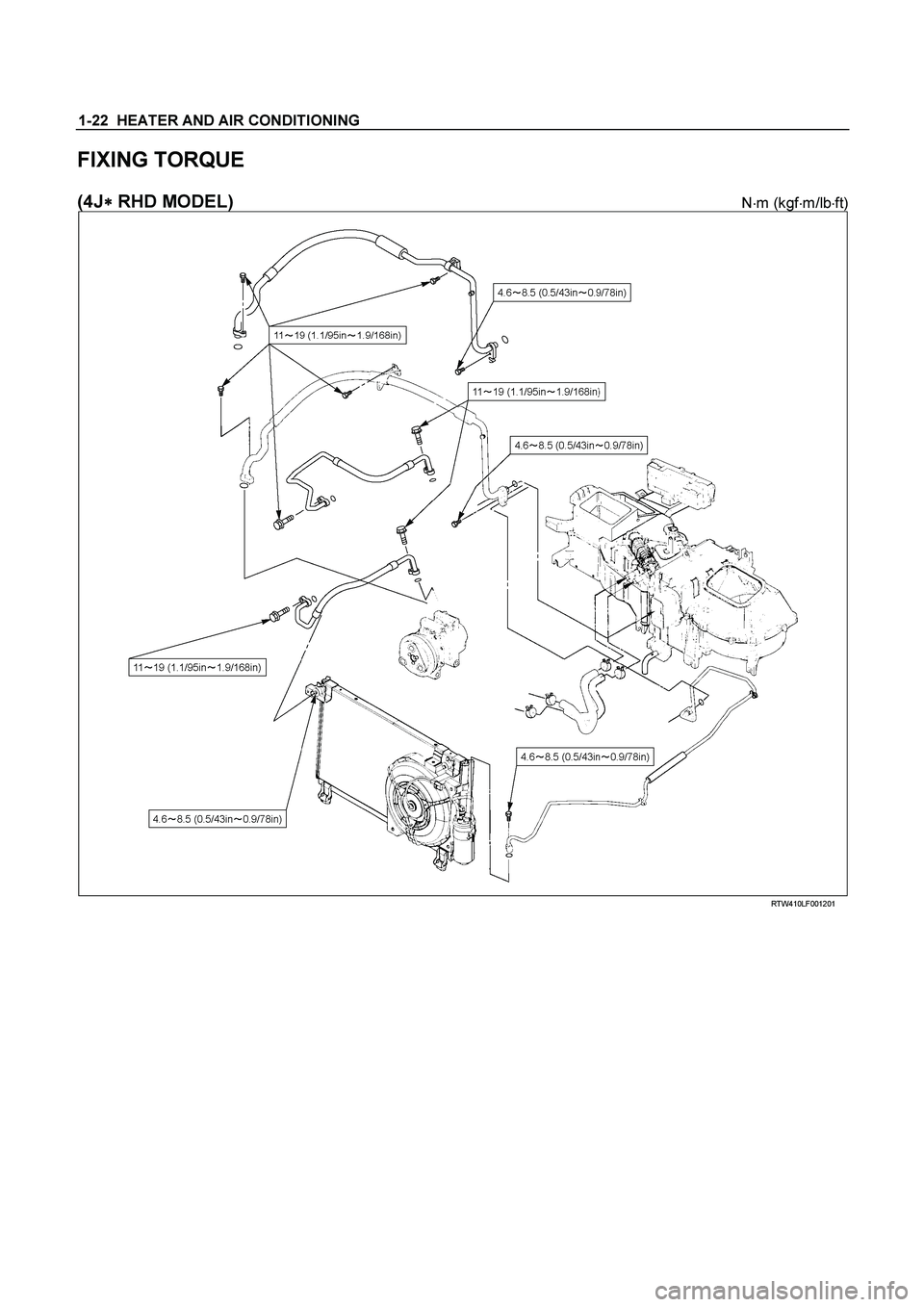
FIXING TORQUE
(4J�
�� � RHD MODEL) N�
m (kgf�
m/lb�
ft)
RTW410LF001201
Page 3038 of 4264

1-28 HEATER AND AIR CONDITIONING
Insert nut into union. First tighten nut by hand as much as
possible. Then, tighten nut to specified torque.
(Refer to "Special Parts Fixing Nuts and Bolts" in this section)
LEAK AT REFRIGERANT LINE
CONNECTIONS
1) Check the torque on the refrigerant line fitting and, if too
loose, tighten to the specified torque.
� Use two wrenches to prevent twisting and damage to the
Line.
�
Do not over tighten.
2) Perform a leak test on the refrigerant line fitting.
3) If the leak is still present, discharge and recover the
refrigerant from the system.
4) Replace the O-rings.
�
O-rings cannot be reused. Always replace with new
ones.
� Be sure to apply specified compressor oil to the new O-
rings.
5) Retighten the refrigerant line fitting to the specified torque.
�
Use two wrenches to prevent twisting and damage to the
line.
6) Evacuate, charge and retest the system.
LEAK IN THE HOSE
If the compressor inlet or outlet hose is leaking, the entire hose
must be replaced. Refrigerant hose must not be cut or spliced
for repair.
1) Locate the leak.
2) Discharge and recover the refrigerant.
3) Remove the hose assembly.
�
Cap the open connections at once.
4) Connect the new hose assembly.
�
Use two wrenches to prevent twisting or damage to the
hose fitting.
�
Tighten the hose fitting to the specified torque.
5) Evacuate, charge and test the system.
COMPRESSOR LEAKS
If leaks are located around the compressor shaft seal or shell,
replace or repair the compressor.
Page 3051 of 4264
HEATER AND AIR CONDITIONING 1-41
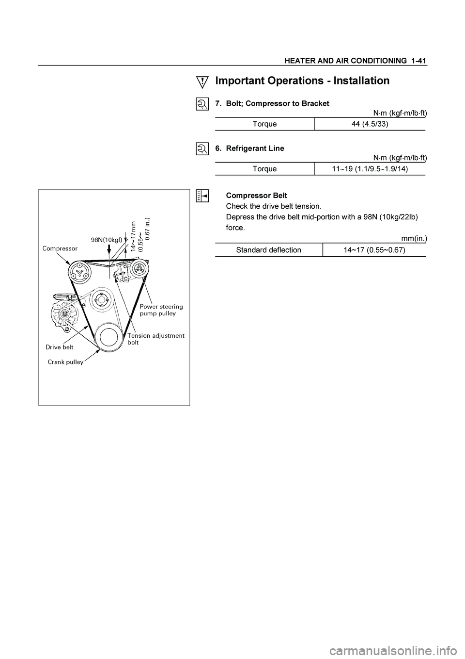
Important Operations - Installation
7. Bolt; Compressor to Bracket
N�m (kgf�m/lb�ft)
Torque 44 (4.5/33)
6. Refrigerant Line
N�m (kgf�m/lb�ft)
Torque 11�19 (1.1/9.5�1.9/14)
Compressor Belt
Check the drive belt tension.
Depress the drive belt mid-portion with a 98N (10kg/22Ib)
force.
mm(in.)
Standard deflection 14~17 (0.55~0.67)
Page 3053 of 4264
HEATER AND AIR CONDITIONING 1-43
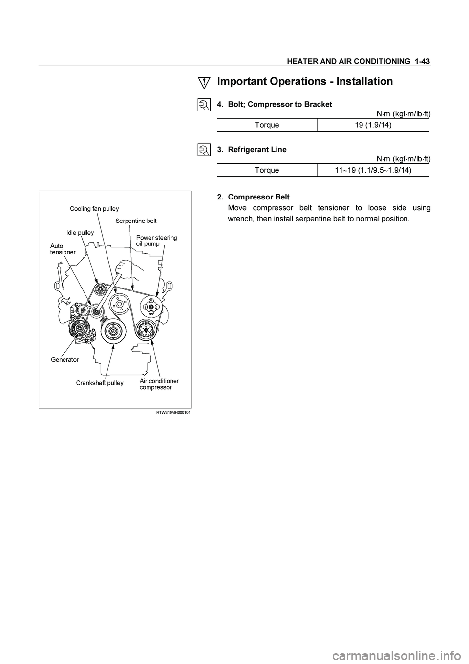
Important Operations - Installation
4. Bolt; Compressor to Bracket
N�m (kgf�m/lb�ft)
Torque 19 (1.9/14)
3. Refrigerant Line
N�m (kgf�m/lb�ft)
Torque 11�19 (1.1/9.5�1.9/14)
RTW310MH000101
2. Compressor Belt
Move compressor belt tensioner to loose side using
wrench, then install serpentine belt to normal position.
Page 3055 of 4264
HEATER AND AIR CONDITIONING 1-45
Important Operations - Installation
4. Bolt; Compressor to Bracket
N�m (kgf�m/lb�ft)
Torque 19 (1.9/14)
3. Refrigerant Line
N�m (kgf�m/lb�ft)
Torque 11�19 (1.1/9.5�1.9/14)
2. Compressor Belt
Move compressor belt tensioner to loose side using
wrench, then install serpentine belt to normal position.
Page 3063 of 4264
HEATER AND AIR CONDITIONING 1-53
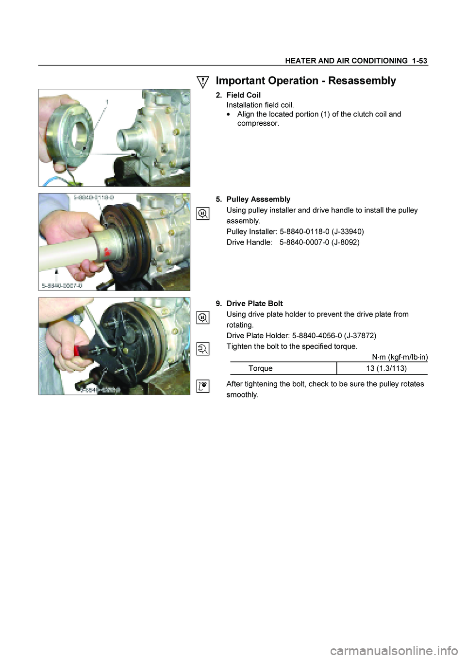
Important Operation - Resassembly
2. Field Coil
Installation field coil.
�
Align the located portion (1) of the clutch coil and
compressor.
5. Pulley Asssembly
Using pulley installer and drive handle to install the pulley
assembly.
Pulley Installer: 5-8840-0118-0 (J-33940)
Drive Handle: 5-8840-0007-0 (J-8092)
9. Drive Plate Bolt
Using drive plate holder to prevent the drive plate from
rotating.
Drive Plate Holder: 5-8840-4056-0 (J-37872)
Tighten the bolt to the specified torque.
N�m (kgf�m/Ib�in)
Torque 13 (1.3/113)
After tightening the bolt, check to be sure the pulley rotates
smoothly.
Page 3119 of 4264

TABLE OF CONTENTS
PAGE
Main Data and Specifications .................................................................................")
MSG MODEL 7B-1
SECTION 7B
MANUAL TRANSMISSION
(MSG MODELS)
TABLE OF CONTENTS
PAGE
Main Data and Specifications .................................................................................... 7B - 2
General Description.................................................................................................... 7B - 3
Torque Specification .................................................................................................. 7B - 4
Repair Kit .................................................................................................................... 7B - 6
Removal and Installation ........................................................................................... 7B - 7
Disassembly ............................................................................................................... 7B - 15
Inspection and Repair ............................................................................................... 7B - 25
Reassembly ................................................................................................................ 7B - 29
Special Service Tool .................................................................................................. 7B - 42
Page 3122 of 4264

Strengt")
7B-4 MSG MODEL
TORQUE SPECIFICATION
STANDDARD BOLTS
The torque values given in the following table should be applied where a particular torque is not specified.
N�
m (kgf�
m/lb�
ft)
Strength 4.8/4T 7T 8.8 9.8/9T
Class Refined Non-Refined
Bolt Identifi-
cation
Bolt
Diameter�
�� �
Pitch (mm)
No mark-
M6 � 1.0 6 (0.6 / 52 lb.in) 7 (0.7 / 61 lb.in) 8 (0.8 / 69 lb.in) -
M8 � 1.25 13 (1.3 / 113 lb.in) 17 (1.7 / 12) 20 (2.0 / 14) 24 (2.4 / 17)
M10 � 1.25 27 (2.8 / 20) 37 (3.8 / 27) 42 (4.3 / 31) 50 (5.1 / 37)
M12 � 1.25 61 (6.3 / 45) 76 (7.8 / 56) 87 (8.9 / 64) 95 (9.7 / 70)
M14 �1.5 96 (9.8 / 71) 116 (11.8 / 85) 133 (13.6 / 98) 142 (14.5 / 105)
M16 � 1.5 130 (13.3 / 96) 170 (17.3 / 125) 193 (19.7 / 143) 200 (20.4 / 148)
M18 � 1.5 188 (19.2 / 139) 244 (24.9 / 180) 278 (28.3 / 205) 287 (29.3 / 212)
M20 � 1.5 258 (26.3 / 190) 337 (34.4 / 249) 385 (39.3 / 284) 396 (40.4 / 292)
M22 � 1.5 332 (33.9 / 245) 453 (46.3 / 335) 517 (52.7 / 381) 530 (54.1 / 391)
M24 � 2.0 449 (45.8 / 331) 570 (58.2 / 421) 651 (66.3 / 480) 692 (70.6 / 511)
* M10 � 1.5 26 (2.7 / 20) 36 (3.7 / 27) 41 (4.2 / 30) 48 (4.9 / 35)
* M12 � 1.75 57 (5.8 / 42) 71 (7.2 / 52) 80 (8.2 / 59) 89 (9.1 / 66)
* M14 � 2.0 89 (9.1 / 66) 110 (11.2 / 81) 125 (12.7 / 92) 133 (13.6 / 98)
* M16 � 2.0 124 (12.7 / 92) 162 (16.5 / 119) 185 (18.9 / 137) 191 (19.5 / 141)
Flange Bolt M6
� 1.0 7 (0.7 / 61 lb.in) 8 (0.8 / 69 lb.in) 9 (0.9 / 78 lb.in) -
M8 � 1.25 15 (1.5 / 11) 19 (1.9 / 14) 22 (2.2 / 16) 26 (2.7 / 20)
M10 � 1.25 31 (3.2 / 23) 41 (4.2 / 30) 47 (4.8 / 35) 56 (5.7 / 41)
M12
� 1.25 69 (7.0 / 51) 85 (8.7 / 63) 97 (9.9 / 72) 106 (10.8 / 78)
M14 � 1.5 104 (10.6 / 77) 126 (12.8 / 93) 144 (14.6 / 106) 154 (15.7 / 114)
M16 � 1.5 145 (14.8 / 127) 188 (19.2 / 139) 214 (21.8 / 158) 221 (22.5 / 163)
M18
� 1.5 - - - -
M20 � 1.5 - - - -
M22 � 1.5 - - - -
M24
� 2.0 - - - -
* M10 � 1.5 30 (3.1 / 22) 40 (4.1 / 30) 46 (4.7 / 34) 54 (5.5 / 40)
* M12 � 1.75 64 (6.5 / 47) 78 (8.0 / 58) 89 (9.1 / 66) 99 (10.1 / 73)
* M14
� 2.0 97 (9.9 / 72) 119 (12.1 / 88) 135 (13.8 / 99.7) 144 (14.7 / 107)
* M16 � 2.0 137 (14.0 / 101) 178 (18.2 / 132) 203 (20.7 / 132) 210 (21.5 / 155)
The asterisk * indicates that the bolts are used for female-threaded parts that are made of soft materials such as
casting, etc.
FLARE NUTS
Pipe diameter mm (in) Torque N�
�� �m (kgf�
�� �m/lb�
�� �ft) Pipe diameter mm (in) Torque N�
�� �m (kgf�
�� �m/lb�
�� �ft)
4.76 (0.187) 16 (1.6 / 12) 10.00 (0.394) 54 (5.5 / 40)
6.35 (0.250) 26 (2.7 / 20) 12.00 (0.472) 88 (9.0 / 65)
8.00 (0.315) 44 (4.5 / 33) 15.00 (0.591) 106 (10.8 / 78)
Standard Hex.
Head Bolt