Page 3130 of 4264
7B-12 MSG MODEL
RTW37BLF000901
10. Install the rear mounting rubber 3 to the transmission 2.
Install the rear mounting rubber
3 to the No.3
crossmember
4.
11. Tighten the rear mounting rubber nuts
1 to the specified
forque.
Rear Mounting Rubber Nut Torque N�
m (kgf�
m/lb�
ft)
41 (4.2 / 30)
Mounting Bolt Torgue N�m (kgf�m/lb�ft)
41 (4.2 / 30)
Page 3131 of 4264
MSG MODEL 7B-13
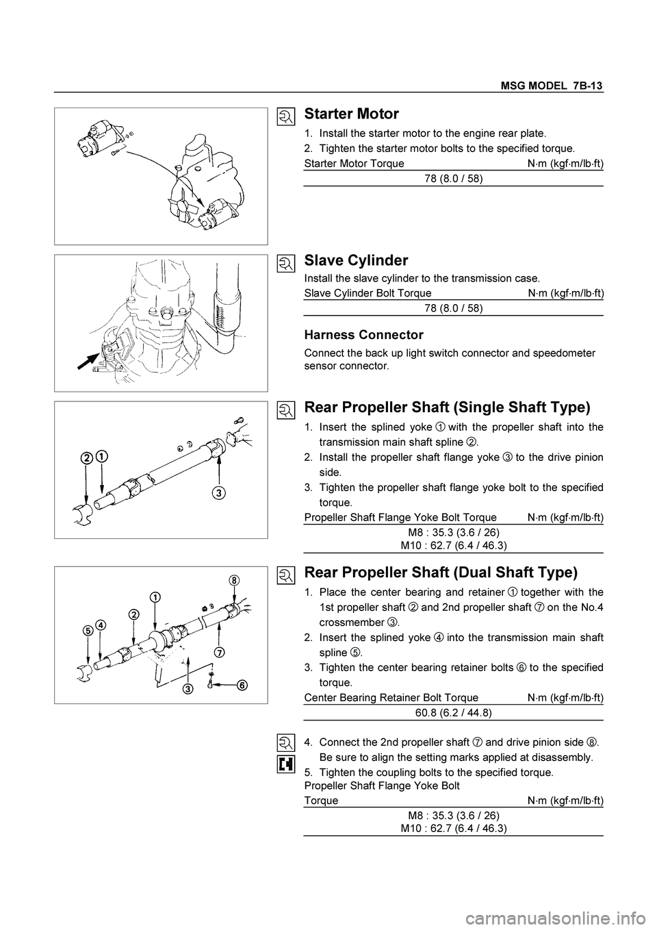
Starter Motor
1. Install the starter motor to the engine rear plate.
2. Tighten the starter motor bolts to the specified torque.
Starter Motor Torque N�
m (kgf�
m/lb�
ft)
78 (8.0 / 58)
Slave Cylinder
Install the slave cylinder to the transmission case.
Slave Cylinder Bolt Torque N�
m (kgf�
m/lb�
ft
)
78 (8.0 / 58)
Harness Connector
Connect the back up light switch connector and speedometer
sensor connector.
Rear Propeller Shaft (Single Shaft Type)
1. Insert the splined yoke 1 with the propeller shaft into the
transmission main shaft spline
2 .
2. Install the propeller shaft flange yoke
3 to the drive pinion
side.
3. Tighten the propeller shaft flange yoke bolt to the specified
torque.
Propeller Shaft Flange Yoke Bolt Torque N�m (kgf�m/lb�ft)
M8 : 35.3 (3.6 / 26)
M10 : 62.7 (6.4 / 46.3)
Rear Propeller Shaft (Dual Shaft Type)
1. Place the center bearing and retainer 1 together with the
1st propeller shaft
2 and 2nd propeller shaft 7 on the No.4
crossmember
3.
2. Insert the splined yoke
4into the transmission main shaft
spline
5.
3. Tighten the center bearing retainer bolts
6 to the specified
torque.
Center Bearing Retainer Bolt Torque N�
m (kgf�
m/lb�
ft)
60.8 (6.2 / 44.8)
4. Connect the 2nd propeller shaft
7 and drive pinion side 8.
Be sure to align the setting marks applied at disassembly.
5. Tighten the coupling bolts to the specified torque.
Propeller Shaft Flange Yoke Bolt
Torque N�
m (kgf�
m/lb�
ft)
M8 : 35.3 (3.6 / 26)
M10 : 62.7 (6.4 / 46.3)
Page 3132 of 4264
7B-14 MSG MODEL
Exhaust Pipe
1. Install the exhaust pipe to the exhaust manifold and the
2nd exhaust pipe.
2. Install the exhaust pipe bracket to the transmission case.
Gear Shift Lever
1. Replenish the transmission case with the specified engine
oil.
Transmission Case Oil lit(US gal.)
1.55 (0.41)
2. Install the gear shift lever to the gear control box.
3. Tighten the gear shift lever cover bolts to the specified
torque.
Shift Lever Cover Bolt Torque N�
m(kgf�
m/lb�
ft)
19.6 (2.0 / 14.5)
4. Install the dust cover and the grommet.
5. Install the front console assembly.
6. Install the gear shift lever knob.
Lowering the Vehicle
1. Place a jack beneath the vehicle.
2. Raise the jack to remove the chassis stands.
3. Lower the vehicle to the ground.
Engine Hood
Align the setting marks(applied at removal)on the engine hood
and the engine hood hinges to install the engine hood.
Battery Cable
Connect the negative (-) cable to the battery terminal.
Page 3153 of 4264
MSG MODEL 7B-35
Important Operations
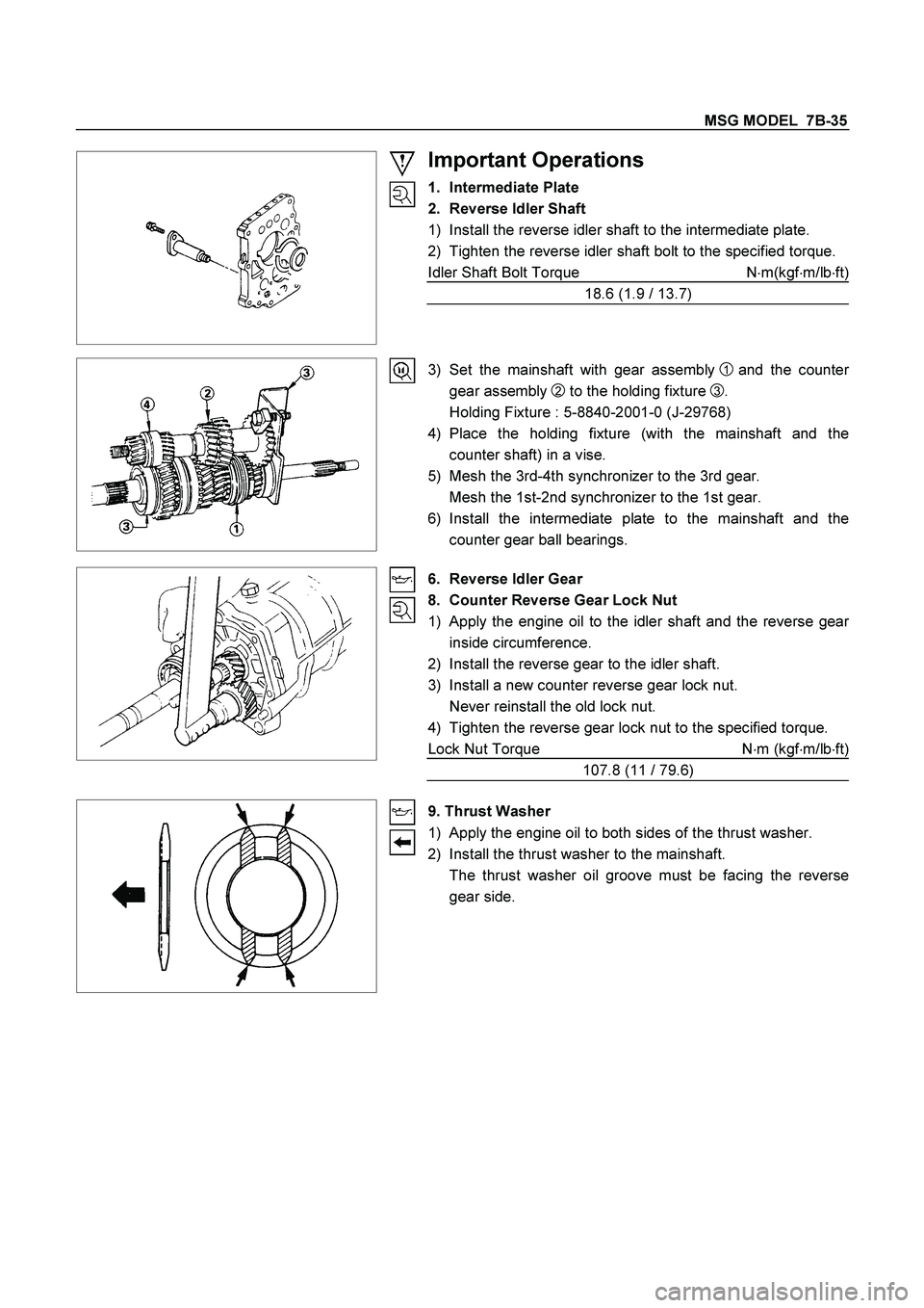
1. Intermediate Plate
2. Reverse Idler Shaft
1) Install the reverse idler shaft to the intermediate plate.
2) Tighten the reverse idler shaft bolt to the specified torque.
Idler Shaft Bolt Torque N�m(kgf�m/lb�ft)
18.6 (1.9 / 13.7)
3) Set the mainshaft with gear assembly
1 and the counter
gear assembly
2 to the holding fixture
3.
Holding Fixture : 5-8840-2001-0 (J-29768)
4) Place the holding fixture (with the mainshaft and the
counter shaft) in a vise.
5) Mesh the 3rd-4th synchronizer to the 3rd gear.
Mesh the 1st-2nd synchronizer to the 1st gear.
6) Install the intermediate plate to the mainshaft and the
counter gear ball bearings.
6. Reverse Idler Gear
8. Counter Reverse Gear Lock Nut
1) Apply the engine oil to the idler shaft and the reverse gear
inside circumference.
2) Install the reverse gear to the idler shaft.
3) Install a new counter reverse gear lock nut.
Never reinstall the old lock nut.
4) Tighten the reverse gear lock nut to the specified torque.
Lock Nut Torque N�m (kgf�m/lb�ft)
107.8 (11 / 79.6)
9. Thrust Washer
1) Apply the engine oil to both sides of the thrust washer.
2) Install the thrust washer to the mainshaft.
The thrust washer oil groove must be facing the reverse
gear side.
Page 3154 of 4264
7B-36 MSG MODEL
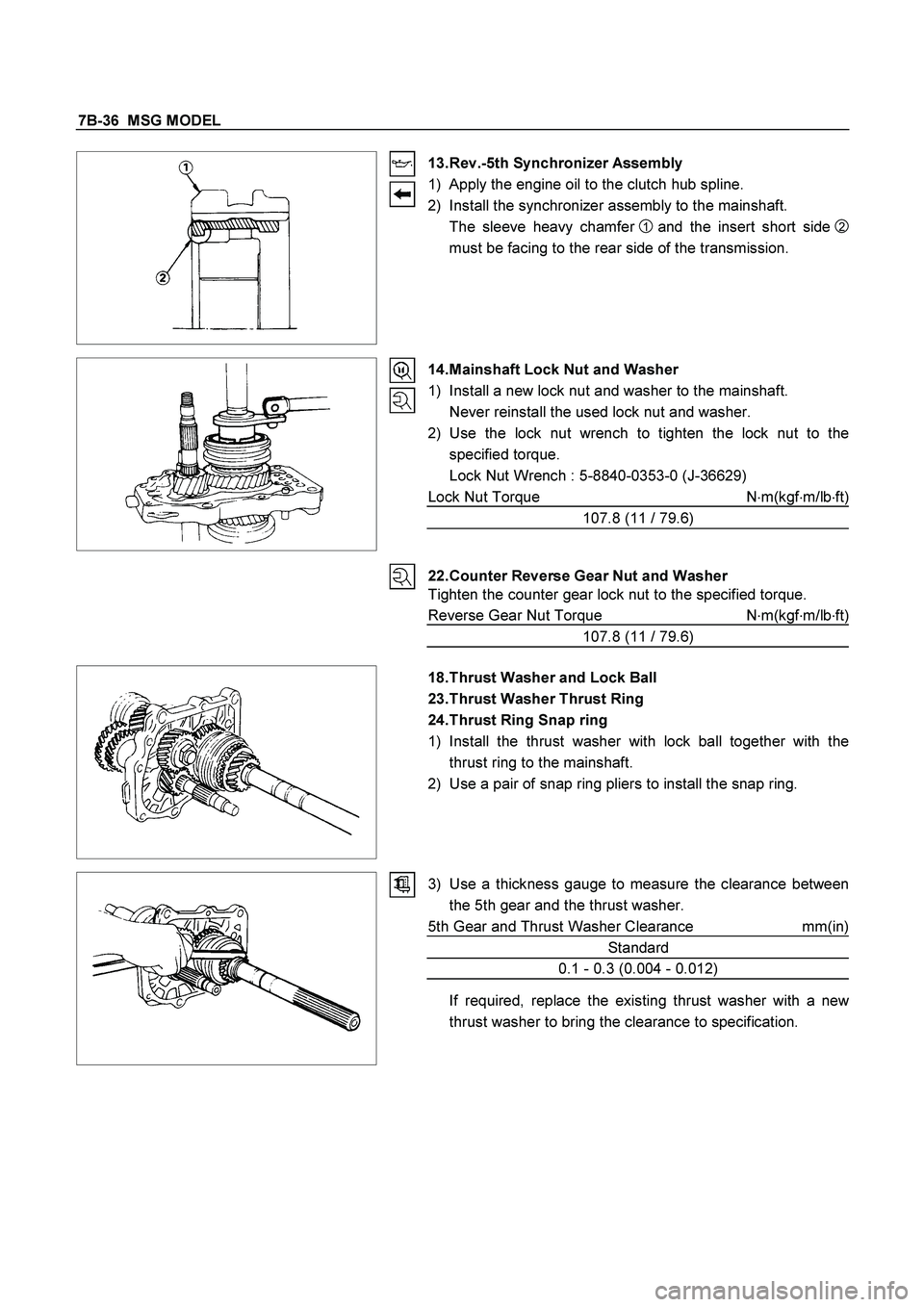
13. Rev.-5th Synchronizer Assembly
1) Apply the engine oil to the clutch hub spline.
2) Install the synchronizer assembly to the mainshaft.
The sleeve heavy chamfer
1 and the insert short side
2
must be facing to the rear side of the transmission.
14. Mainshaft Lock Nut and Washer
1) Install a new lock nut and washer to the mainshaft.
Never reinstall the used lock nut and washer.
2) Use the lock nut wrench to tighten the lock nut to the
specified torque.
Lock Nut Wrench : 5-8840-0353-0 (J-36629)
Lock Nut Torque N�m(kgf�m/lb�ft)
107.8 (11 / 79.6)
22. Counter Reverse Gear Nut and Washer
Tighten the counter gear lock nut to the specified torque.
Reverse Gear Nut Torque N�
m(kgf�
m/lb�
ft)
107.8 (11 / 79.6)
18. Thrust Washer and Lock Ball
23. Thrust Washer Thrust Ring
24. Thrust Ring Snap ring
1) Install the thrust washer with lock ball together with the
thrust ring to the mainshaft.
2) Use a pair of snap ring pliers to install the snap ring.
3) Use a thickness gauge to measure the clearance between
the 5th gear and the thrust washer.
5th Gear and Thrust Washer Clearance mm(in)
Standard
0.1 - 0.3 (0.004 - 0.012)
If required, replace the existing thrust washer with a new
thrust washer to bring the clearance to specification.
Page 3157 of 4264
MSG MODEL 7B-39
Important Operations
2. 1st-2nd Shift Arm
3. 3rd-4th Shift Arm
7. Rev.-5th Shift Arm
1) Hold a round bar against the shift rod end lower face to
protect it against damage.
2) Use a spring pin installer to install the spring pin to the shift
arm and the shift rod.
Never reinstall the used spring pins.
11. Detent spring Plate and Gasket.
1) Install the new detent plete and new gasket onto the
transmission case into the correct direction.
2) Tighten the detent spring plate bolts to the specified torque.
Detent Spring Plate Bolt Torque N�
m(kgf�
m/lb�
ft)
18.6 (1.9 / 13.7)
Page 3159 of 4264
MSG MODEL 7B-41
RTW47BSH000201
Important Operations
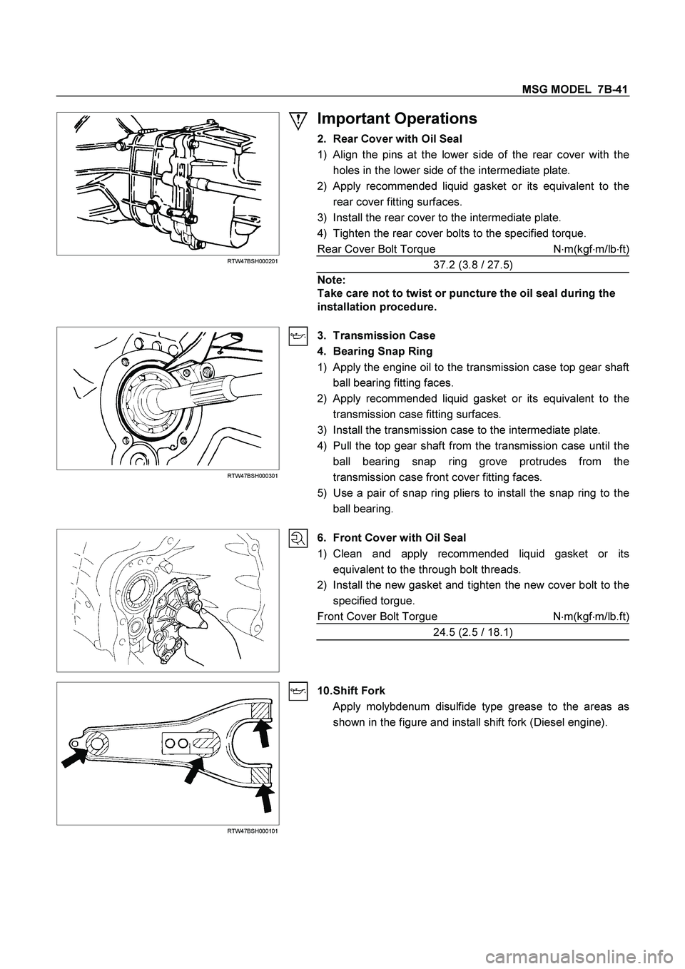
2. Rear Cover with Oil Seal
1)
Align the pins at the lower side of the rear cover with the
holes in the lower side of the intermediate plate.
2)
Apply recommended liquid gasket or its equivalent to the
rear cover fitting surfaces.
3) Install the rear cover to the intermediate plate.
4) Tighten the rear cover bolts to the specified torque.
Rear Cover Bolt Torque N�
m(kgf�
m/lb�
ft)
37.2 (3.8 / 27.5)
Note:
Take care not to twist or puncture the oil seal during the
installation procedure.
RTW47BSH000301
3. Transmission Case
4. Bearing Snap Ring
1) Apply the engine oil to the transmission case top gear shaft
ball bearing fitting faces.
2)
Apply recommended liquid gasket or its equivalent to the
transmission case fitting surfaces.
3) Install the transmission case to the intermediate plate.
4) Pull the top gear shaft from the transmission case until the
ball bearing snap ring grove protrudes from the
transmission case front cover fitting faces.
5) Use a pair of snap ring pliers to install the snap ring to the
ball bearing.
6. Front Cover with Oil Seal
1) Clean and apply recommended liquid gasket or its
equivalent to the through bolt threads.
2) Install the new gasket and tighten the new cover bolt to the
specified torgue.
Front Cover Bolt Torgue N�
m(kgf�
m/lb.ft)
24.5 (2.5 / 18.1)
RTW47BSH000101
10. Shift Fork
Apply molybdenum disulfide type grease to the areas as
shown in the figure and install shift fork (Diesel engine).
Page 3167 of 4264
MANUAL TRANSMISSION 7B1-3
Service Precaution
WARNING: THIS VEHICLE HAS A SUPPLEMENTAL
RESTRAINT SYSTEM (SRS). REFER TO THE SRS
COMPONENT AND WIRING LOCATION VIEW IN
ORDER TO DETERMINE WHETHER YOU ARE
PERFORMING SERVICE ON OR NEAR THE SRS
COMPONENTS OR THE SRS WIRING. WHEN YOU
ARE PERFORMING SERVICE ON OR NEAR THE
SRS COMPONENTS OR THE SRS WIRING, REFER
TO THE SRS SERVICE INFORMATION. FAILURE TO
FOLLOW WARNINGS COULD RESULT IN POSSIBLE
AIR BAG DEPLOYMENT, PERSONAL INJURY, OR
OTHERWISE UNNEEDED SRS SYSTEM REPAIRS. CAUTION: Always use the correct fastener in the
proper location. When you replace a fastener, use
ONLY the exact part number for that application.
ISUZU will call out those fasteners that require a
replacement after removal. ISUZU will also call out
the fasteners that require thread lockers or thread
sealant. UNLESS OTHERWISE SPECIFIED, do not
use supplemental coatings (Paints, greases, or
other corrosion inhibitors) on threaded fasteners or
fastener joint interfaces. Generally, such coatings
adversely affect the fastener torque and the joint
clamping force, and may damage the fastener.
When you install fasteners, use the correct
tightening sequence and specifications. Following
these instructions can help you avoid damage to
parts and systems.