2004 ISUZU TF SERIES Camshaft
[x] Cancel search: CamshaftPage 1131 of 4264
TROUBLESHOOTING 6 – 11
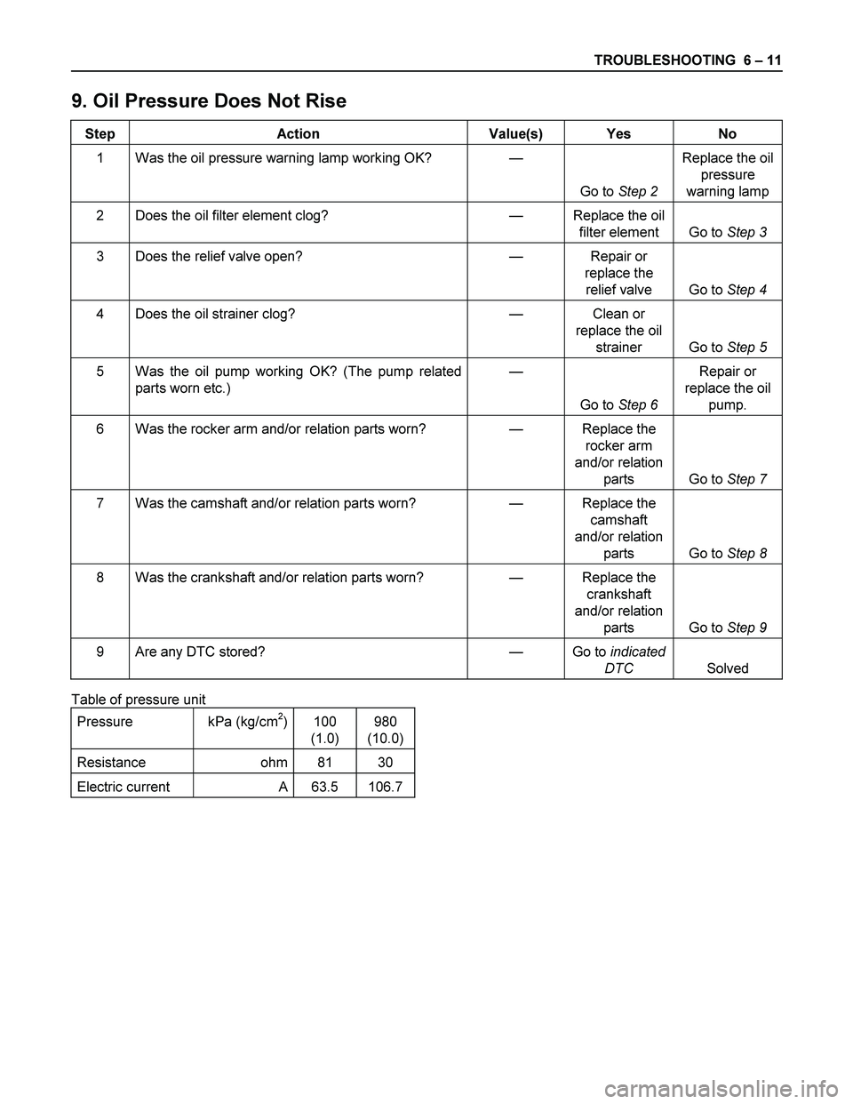
9. Oil Pressure Does Not Rise
Step Action Value(s) Yes No
1 Was the oil pressure warning lamp working OK? —
Go to Step 2 Replace the oil
pressure
warning lamp
2 Does the oil filter element clog? — Replace the oil
filter element Go to Step 3
3 Does the relief valve open? — Repair or
replace the
relief valve Go to Step 4
4 Does the oil strainer clog? — Clean or
replace the oil
strainer Go to Step 5
5 Was the oil pump working OK? (The pump related
parts worn etc.) —
Go to Step 6 Repair or
replace the oil
pump.
6 Was the rocker arm and/or relation parts worn? — Replace the
rocker arm
and/or relation
parts Go to Step 7
7 Was the camshaft and/or relation parts worn? — Replace the
camshaft
and/or relation
parts Go to Step 8
8 Was the crankshaft and/or relation parts worn? — Replace the
crankshaft
and/or relation
parts Go to Step 9
9 Are any DTC stored? — Go to indicated
DTC Solved
Table of pressure unit
Pressure kPa (kg/cm
2) 100
(1.0) 980
(10.0)
Resistance ohm 81 30
Electric current A 63.5 106.7
Page 1142 of 4264
6A – 2 ENGINE MECHANICAL
Disassembly ............................................................................................................... 6A- 47
Internal Parts........................................................................................................... 6A- 47
Major Components.............................................................................................. 6A- 47
Minor Components ............................................................................................. 6A- 56
Rocker Arm Shaft and Rocker Arm................................................................ 6A- 56
Cylinder Head .................................................................................................. 6A- 57
Piston and Connecting Rod ........................................................................... 6A- 59
Inspection and Repair................................................................................................ 6A- 61
Cylinder Head ......................................................................................................... 6A- 61
Rocker Arm Shaft and Rocker Arm ....................................................................... 6A- 68
Cylinder Body ......................................................................................................... 6A- 69
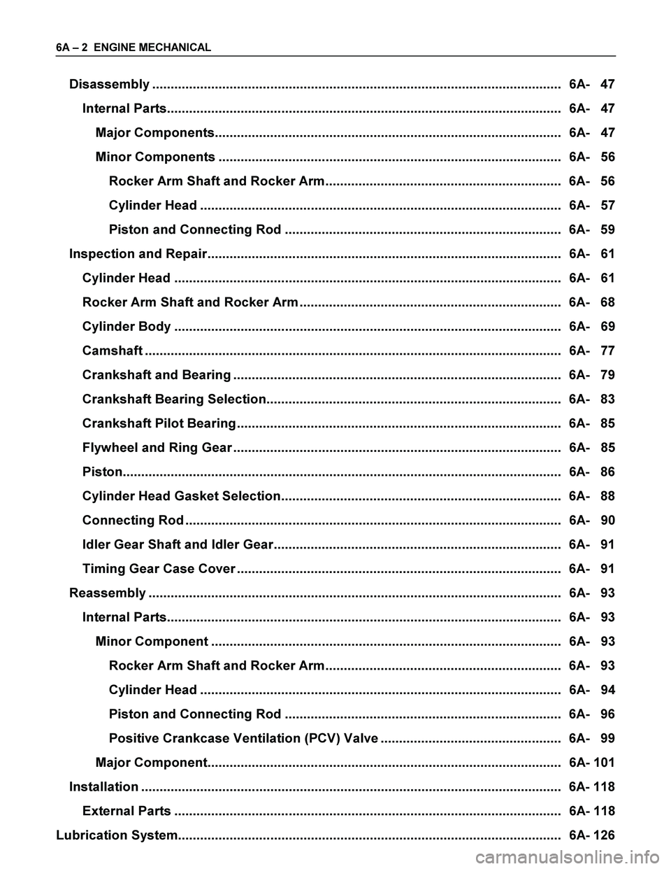
Camshaft ................................................................................................................. 6A- 77
Crankshaft and Bearing ......................................................................................... 6A- 79
Crankshaft Bearing Selection................................................................................ 6A- 83
Crankshaft Pilot Bearing........................................................................................ 6A- 85
Flywheel and Ring Gear ......................................................................................... 6A- 85
Piston....................................................................................................................... 6A- 86
Cylinder Head Gasket Selection............................................................................ 6A- 88
Connecting Rod ...................................................................................................... 6A- 90
Idler Gear Shaft and Idler Gear.............................................................................. 6A- 91
Timing Gear Case Cover ........................................................................................ 6A- 91
Reassembly ................................................................................................................ 6A- 93
Internal Parts........................................................................................................... 6A- 93
Minor Component ............................................................................................... 6A- 93
Rocker Arm Shaft and Rocker Arm................................................................ 6A- 93
Cylinder Head .................................................................................................. 6A- 94
Piston and Connecting Rod ........................................................................... 6A- 96
Positive Crankcase Ventilation (PCV) Valve ................................................. 6A- 99
Major Component................................................................................................ 6A- 101
Installation .................................................................................................................. 6A- 118
External Parts ......................................................................................................... 6A- 118
Lubrication System........................................................................................................ 6A- 126
Page 1151 of 4264
ENGINE MECHANICAL 6A – 11
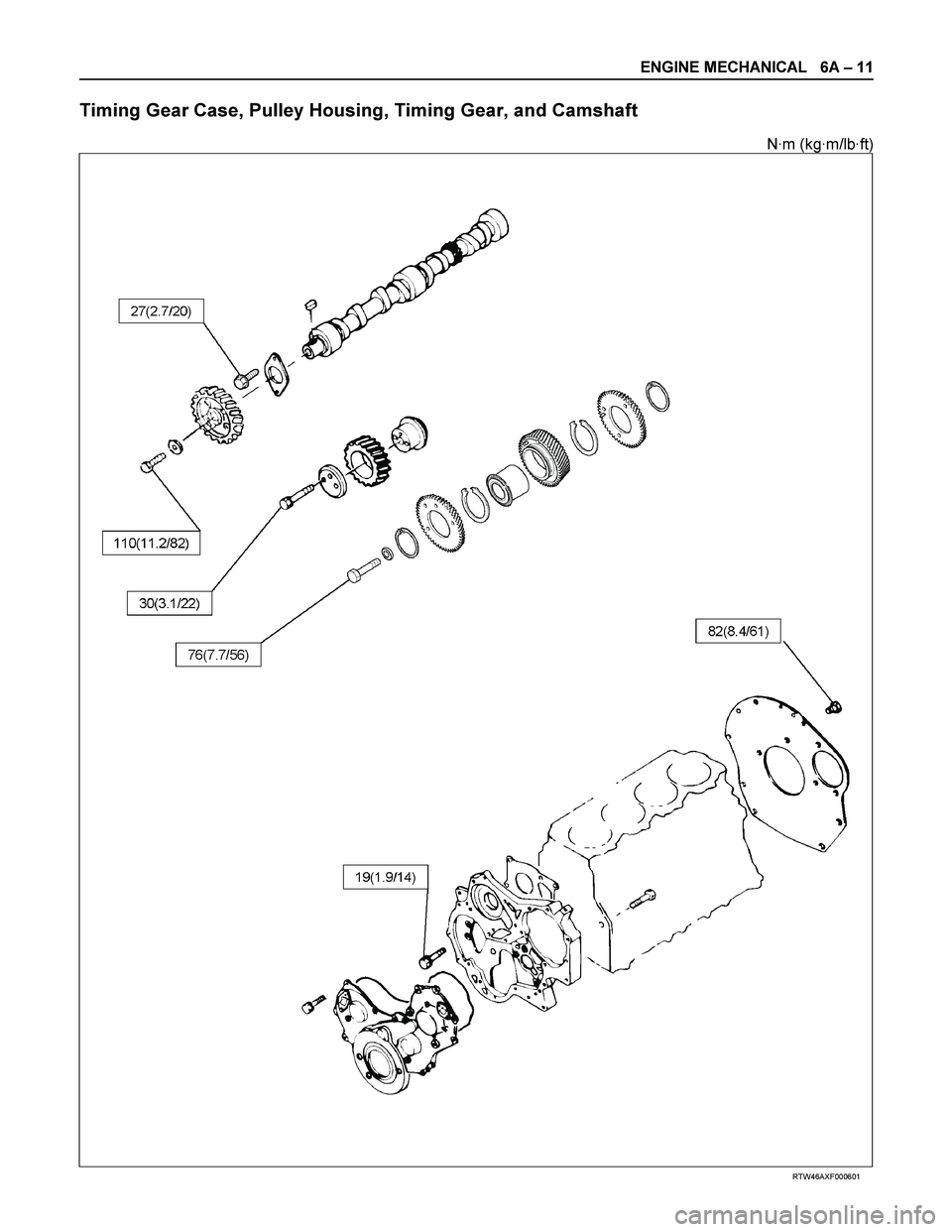
Timing Gear Case, Pulley Housing, Timing Gear, and Camshaft
N·m (kg·m/lb·ft)
RTW46AXF000601
Page 1189 of 4264
ENGINE MECHANICAL 6A – 49
014R300005
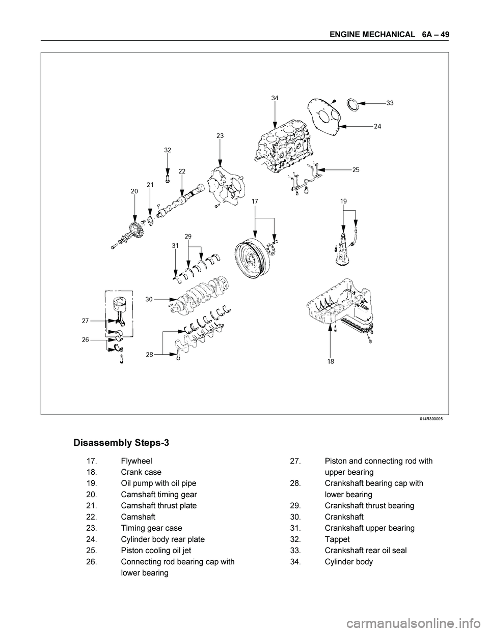
Disassembly Steps-3
17. Flywheel 27. Piston and connecting rod with
18. Crank case upper bearing
19. Oil pump with oil pipe 28. Crankshaft bearing cap with
20. Camshaft timing gear lower bearing
21. Camshaft thrust plate 29. Crankshaft thrust bearing
22. Camshaft 30. Crankshaft
23. Timing gear case 31. Crankshaft upper bearing
24. Cylinder body rear plate 32. Tappet
25. Piston cooling oil jet 33. Crankshaft rear oil seal
26. Connecting rod bearing cap with 34. Cylinder body
lower bearing
Page 1191 of 4264
ENGINE MECHANICAL 6A – 51
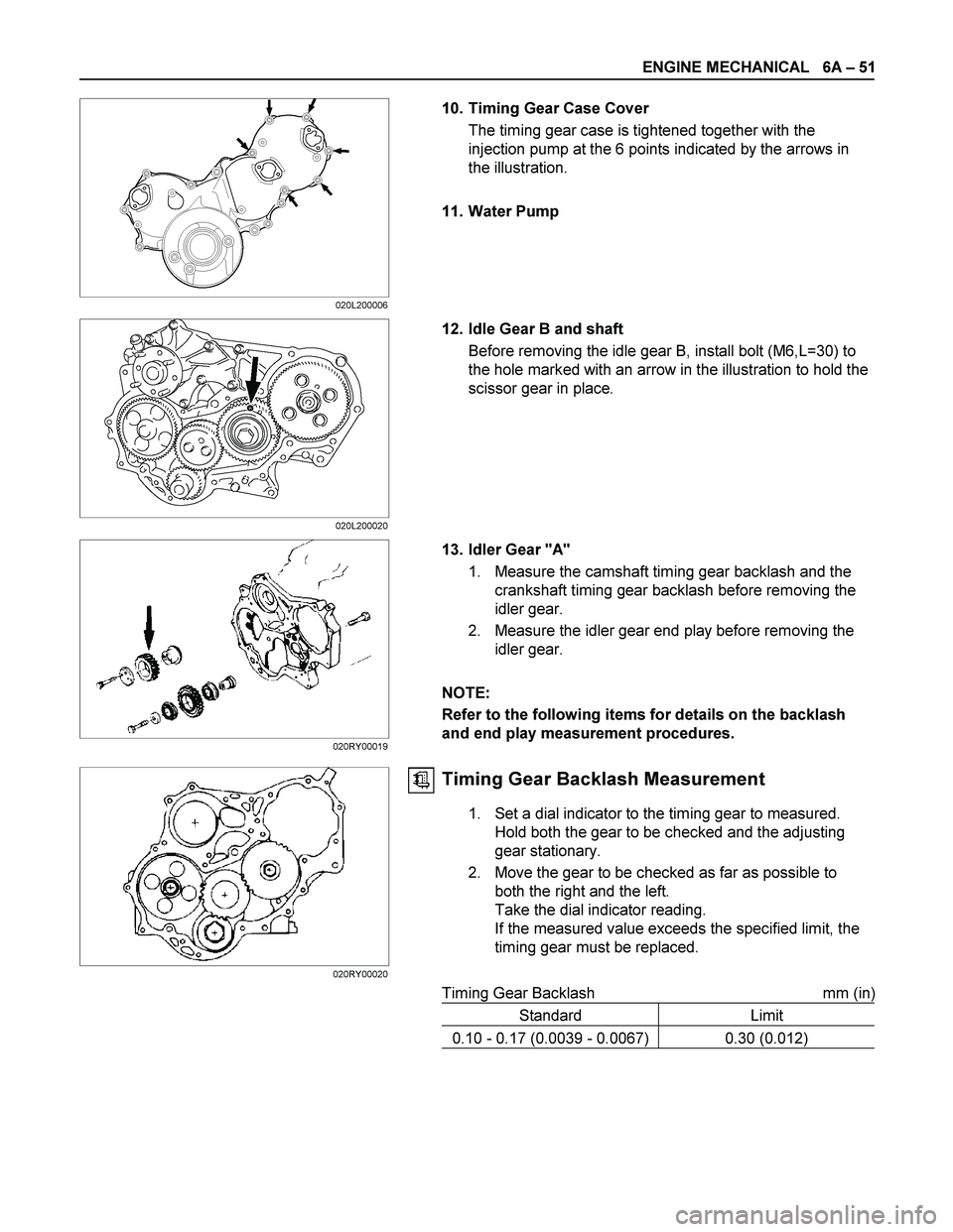
10. Timing Gear Case Cover
The timing gear case is tightened together with the
injection pump at the 6 points indicated by the arrows in
the illustration.
11. Water Pump
12. Idle Gear B and shaft
Before removing the idle gear B, install bolt (M6,L=30) to
the hole marked with an arrow in the illustration to hold the
scissor gear in place.
13. Idler Gear "A"
1. Measure the camshaft timing gear backlash and the
crankshaft timing gear backlash before removing the
idler gear.
2. Measure the idler gear end play before removing the
idler gear.
NOTE:
Refer to the following items for details on the backlash
and end play measurement procedures.
Timing Gear Backlash Measurement
1. Set a dial indicator to the timing gear to measured.
Hold both the gear to be checked and the adjusting
gear stationary.
2. Move the gear to be checked as far as possible to
both the right and the left.
Take the dial indicator reading.
If the measured value exceeds the specified limit, the
timing gear must be replaced.
Timing Gear Backlash mm (in)
Standard Limit
0.10 - 0.17 (0.0039 - 0.0067) 0.30 (0.012)
020L200006
020L200020
020RY00019
020RY00020
Page 1193 of 4264
ENGINE MECHANICAL 6A – 53
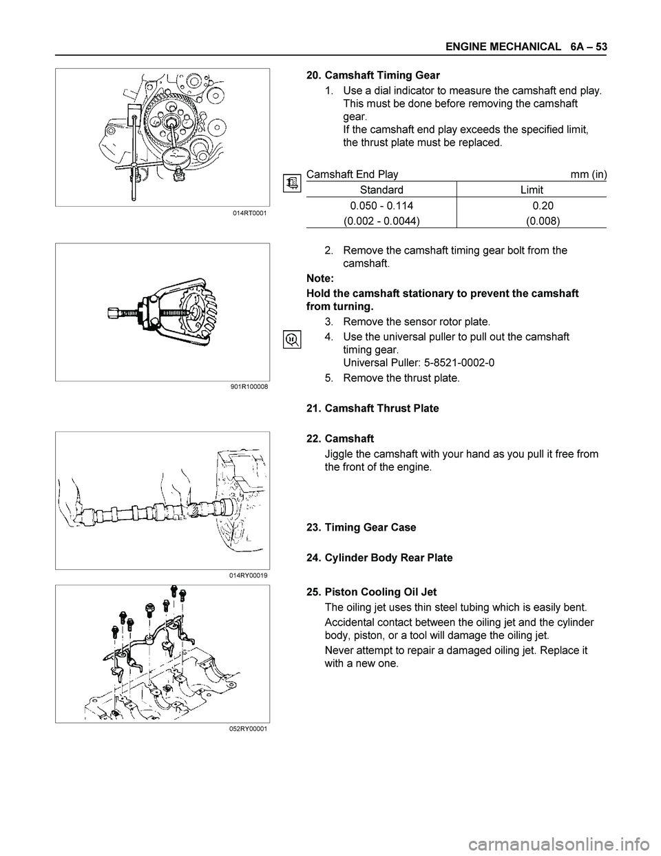
20. Camshaft Timing Gear
1. Use a dial indicator to measure the camshaft end play.
This must be done before removing the camshaft
gear.
If the camshaft end play exceeds the specified limit,
the thrust plate must be replaced.
Camshaft End Play mm (in)
Standard Limit
0.050 - 0.114
(0.002 - 0.0044) 0.20
(0.008)
2. Remove the camshaft timing gear bolt from the
camshaft.
Note:
Hold the camshaft stationary to prevent the camshaft
from turning.
3. Remove the sensor rotor plate.
4. Use the universal puller to pull out the camshaft
timing gear.
Universal Puller: 5-8521-0002-0
5. Remove the thrust plate.
21. Camshaft Thrust Plate
22. Camshaft
Jiggle the camshaft with your hand as you pull it free from
the front of the engine.
23. Timing Gear Case
24. Cylinder Body Rear Plate
25. Piston Cooling Oil Jet
The oiling jet uses thin steel tubing which is easily bent.
Accidental contact between the oiling jet and the cylinder
body, piston, or a tool will damage the oiling jet.
Never attempt to repair a damaged oiling jet. Replace it
with a new one.
014RT0001
901R100008
014RY00019
052RY00001
Page 1217 of 4264
ENGINE MECHANICAL 6A – 77
CAMSHAFT
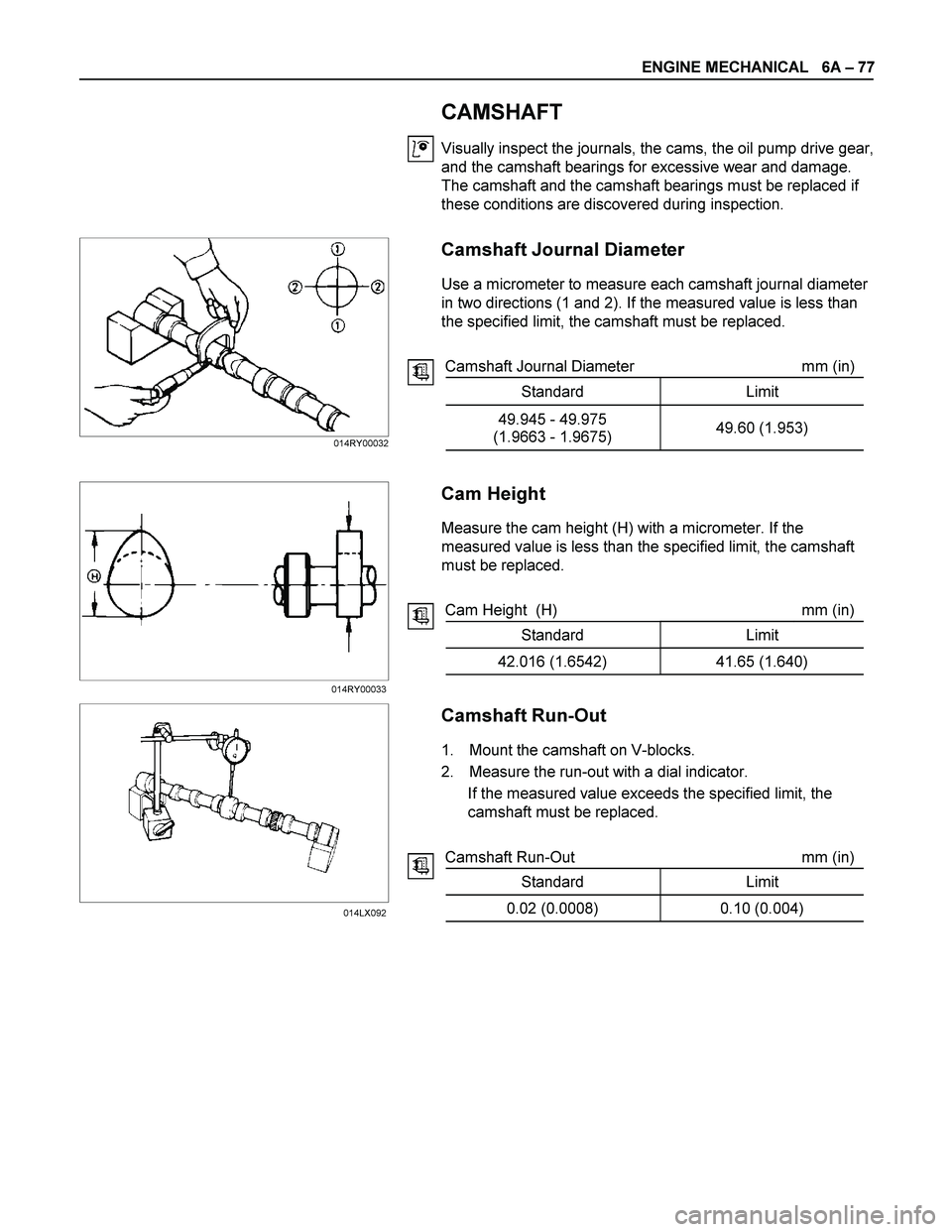
Visually inspect the journals, the cams, the oil pump drive gear,
and the camshaft bearings for excessive wear and damage.
The camshaft and the camshaft bearings must be replaced if
these conditions are discovered during inspection.
Camshaft Journal Diameter
Use a micrometer to measure each camshaft journal diameter
in two directions (1 and 2). If the measured value is less than
the specified limit, the camshaft must be replaced.
Camshaft Journal Diameter mm (in)
Standard Limit
49.945 - 49.975
(1.9663 - 1.9675) 49.60 (1.953)
Cam Height
Measure the cam height (H) with a micrometer. If the
measured value is less than the specified limit, the camshaft
must be replaced.
Cam Height (H) mm (in)
Standard Limit
42.016 (1.6542) 41.65 (1.640)
Camshaft Run-Out
1. Mount the camshaft on V-blocks.
2. Measure the run-out with a dial indicator.
If the measured value exceeds the specified limit, the
camshaft must be replaced.
Camshaft Run-Out mm (in)
Standard Limit
0.02 (0.0008) 0.10 (0.004)
014RY00032
014RY00033
014LX092
Page 1218 of 4264

6A – 78 ENGINE MECHANICAL
Camshaft and Camshaft Bearing Clearance
Use an inside dial indicator to measure the camshaft bearing
inside diameter.
Crankshaft Bearing Inside Diameter mm (in)
Standard Limit
50.00 - 50.03
(1.968 - 1.970) 50.08 (1.972)
If the clearance between the camshaft bearing inside diameter
and the journal exceeds the specified limit, the camshaft
bearing must be replaced.
Camshaft Bearing Clearance mm (in)
Standard Limit
0.055 (0.0022) 0.12 (0.005)
Camshaft Bearing Replacement
Camshaft Bearing Removal
1. Remove the cylinder body plug plate.
2. Use the bearing replacer to remove the camshaft bearing.
Bearing Replacer: 5-8840-2038-0
Camshaft Bearing Installation
1. Align the bearing oil holes with the cylinder body oil holes.
2. Use the replacer to install the camshaft bearing.
Bearing Replacer: 5-8840-2038-0
014RY00034
014RY00035
014RY00036