Page 2833 of 4264

ENGINE DRIVEABILITY AND EMISSIONS 6E–257
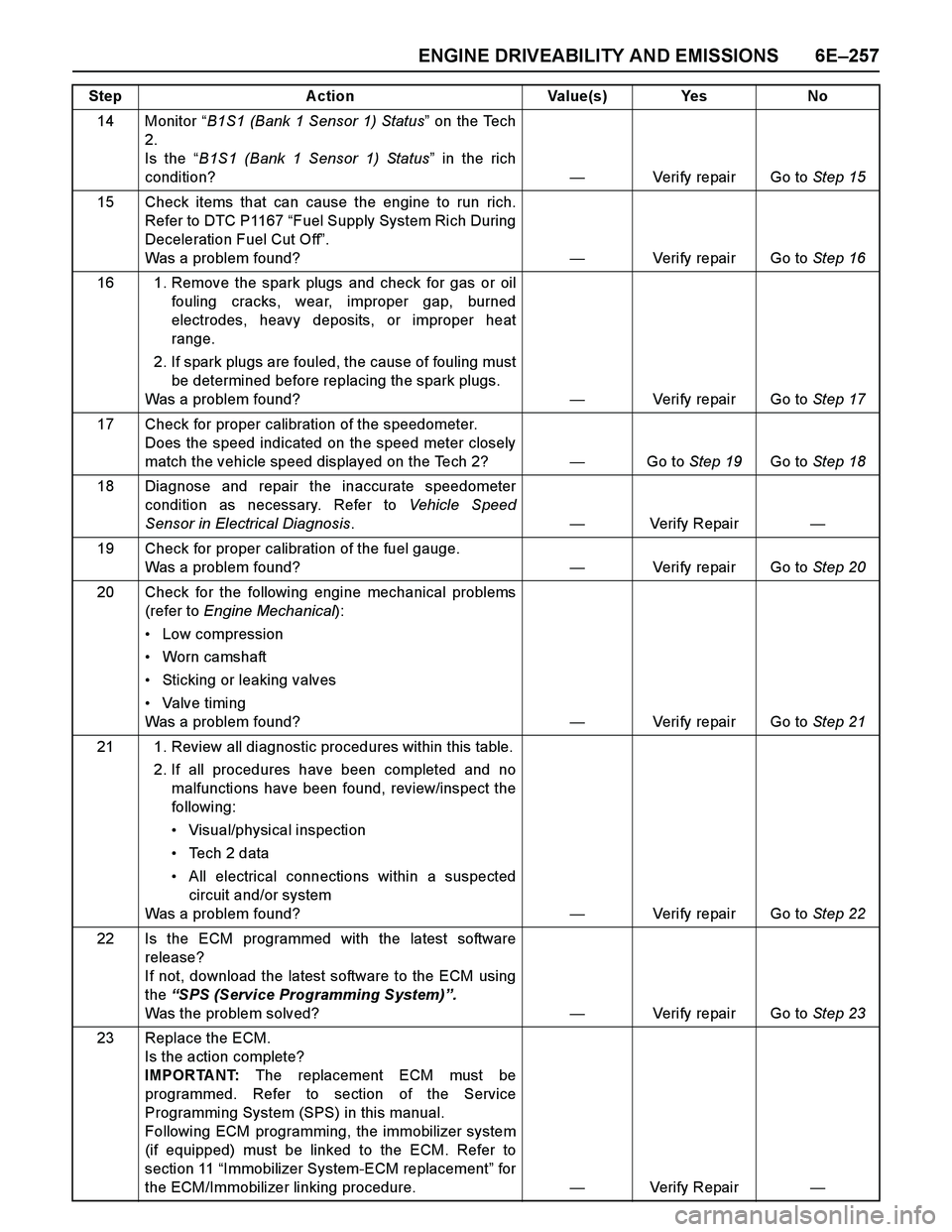
14 Monitor “B1S1 (Bank 1 Sensor 1) Status” on the Tech
2.
Is the “B1S1 (Bank 1 Sensor 1) Status” in the rich
condition?—Verify repair Go to Step 15
15 Check items that can cause the engine to run rich.
Refer to DTC P1167 “Fuel Supply System Rich During
Deceleration Fuel Cut Off”.
Was a problem found?—Verify repair Go to Step 16
16 1. Remove the spark plugs and check for gas or oil
fouling cracks, wear, improper gap, burned
electrodes, heavy deposits, or improper heat
range.
2. If spark plugs are fouled, the cause of fouling must
be determined before replacing the spark plugs.
Was a problem found?—Verify repair Go to Step 17
17 Check for proper calibration of the speedometer.
Does the speed indicated on the speed meter closely
match the vehicle speed displayed on the Tech 2?—Go to Step 19Go to Step 18
18 Diagnose and repair the inaccurate speedometer
condition as necessary. Refer to Vehicle Speed
Sensor in Electrical Diagnosis.—Verify Repair—
19 Check for proper calibration of the fuel gauge.
Was a problem found?—Verify repair Go to Step 20
20 Check for the following engine mechanical problems
(refer to Engine Mechanical):
Low compression
Worn camshaft
Sticking or leaking valves
Valve timing
Was a problem found?—Verify repair Go to Step 21
21 1. Review all diagnostic procedures within this table.
2. If all procedures have been completed and no
malfunctions have been found, review/inspect the
followi ng:
Visual/physical inspection
Te c h 2 d a t a
All electrical connections within a suspected
circuit and/or system
Was a problem found?—Verify repair Go to Step 22
22 Is the ECM programmed with the latest software
release?
If not, download the latest software to the ECM using
the “SPS (Service Programming System)”.
Was the problem solved?—Verify repair Go to Step 23
23 Replace the ECM.
Is the action complete?
IMPORTANT: The replacement ECM must be
programmed. Refer to section of the Service
Programming System (SPS) in this manual.
Following ECM programming, the immobilizer system
(if equipped) must be linked to the ECM. Refer to
section 11 “Immobilizer System-ECM replacement” for
the ECM/Immobilizer linking procedure.—Verify Repair— Step Action Value(s) Yes No
Page 2835 of 4264

ENGINE DRIVEABILITY AND EMISSIONS 6E–259
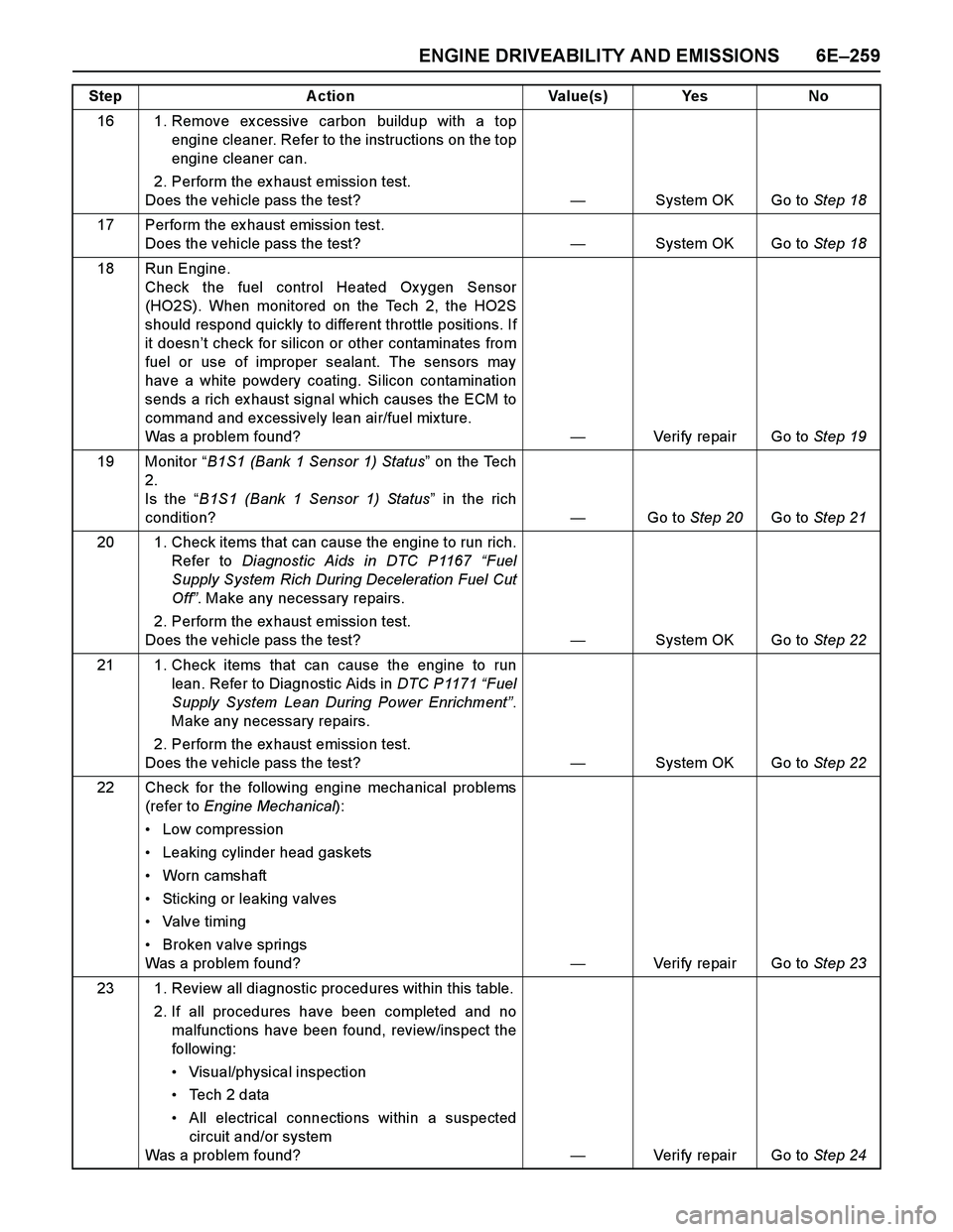
16 1. Remove ex cessive carbon buildup with a top
engine cleaner. Refer to the instructions on the top
engine cleaner can.
2. Perform the ex haust emission test.
Does the vehicle pass the test? —System OK Go to Step 18
17 Perform the ex haust emission test.
Does the vehicle pass the test?—System OK Go to Step 18
18 Run Engine.
Check the fuel control Heated Ox ygen Sensor
(HO2S). When monitored on the Tech 2, the HO2S
should respond quickly to different throttle positions. If
it doesn’t check for silicon or other contaminates from
fuel or use of improper sealant. The sensors may
have a white powdery coating. Silicon contamination
sends a rich ex haust signal which causes the ECM to
command and excessively lean air/fuel mix ture.
Was a problem found?—Verify repair Go to Step 19
19 Monitor “B1S1 (Bank 1 Sensor 1) Status” on the Tech
2.
Is the “B1S1 (Bank 1 Sensor 1) Status” in the rich
condition?—Go to Step 20Go to Step 21
20 1. Check items that can cause the engine to run rich.
Refer to Diagnostic Aids in DTC P1167 “Fuel
Supply System Rich During Deceleration Fuel Cut
Off”. Make any necessary repairs.
2. Perform the ex haust emission test.
Does the vehicle pass the test? —System OK Go to Step 22
21 1. Check items that can cause the engine to run
lean. Refer to Diagnostic Aids in DTC P1171 “Fuel
Supply System Lean During Power Enrichment”.
Make any necessary repairs.
2. Perform the ex haust emission test.
Does the vehicle pass the test?—System OK Go to Step 22
22 Check for the following engine mechanical problems
(refer to Engine Mechanical):
Low compression
Leaking cylinder head gaskets
Worn camshaft
Sticking or leaking valves
Valve timing
Broken valve springs
Was a problem found?—Verify repair Go to Step 23
23 1. Review all diagnostic procedures within this table.
2. If all procedures have been completed and no
malfunctions have been found, review/inspect the
followi ng:
Visual/physical inspection
Te c h 2 d a t a
All electrical connections within a suspected
circuit and/or system
Was a problem found?—Verify repair Go to Step 24 Step Action Value(s) Yes No
Page 2839 of 4264

ENGINE DRIVEABILITY AND EMISSIONS 6E–263
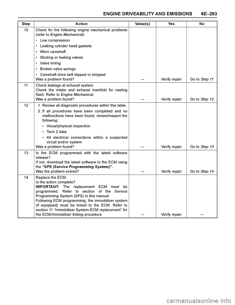
10 Check for the following engine mechanical problems
(refer to Engine Mechanical):
Low compression
Leaking cylinder head gaskets
Worn camshaft
Sticking or leaking valves
Valve timing
Broken valve springs
Camshaft drive belt slipped or stripped
Was a problem found?—Verify repair Go to Step 11
11 Check leakage at exhaust system.
Check the intake and ex haust manifold for casting
flash. Refer to Engine Mechanical.
Was a problem found?—Verify repair Go to Step 12
12 1. Review all diagnostic procedures within this table.
2. If all procedures have been completed and no
malfunctions have been found, review/inspect the
followi ng:
Visual/physical inspection
Te c h 2 d a t a
All electrical connections within a suspected
circuit and/or system
Was a problem found?—Verify repair Go to Step 13
13 Is the ECM programmed with the latest software
release?
If not, download the latest software to the ECM using
the “SPS (Service Programming System)”.
Was the problem solved?—Verify repair Go to Step 14
14 Replace the ECM.
Is the action complete?
IMPORTANT: The replacement ECM must be
programmed. Refer to section of the Service
Programming System (SPS) in this manual.
Following ECM programming, the immobilizer system
(if equipped) must be linked to the ECM. Refer to
section 11 “Immobilizer System-ECM replacement” for
the ECM/Immobilizer linking procedure.—Veri fy repai r— Step Action Value(s) Yes No
Page 2874 of 4264

6G-2 ENGINE LUBRICATION
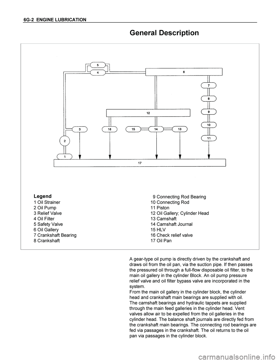
General Description
Legend
1 Oil Strainer
2 Oil Pump
3 Relief Valve
4 Oil Filter
5 Safety Valve
6 Oil Gallery
7 Crankshaft Bearing
8 Crankshaft9 Connecting Rod Bearing
10 Connecting Rod
11 Piston
12 Oil Gallery; Cylinder Head
13 Camshaft
14 Camshaft Journal
15 HLV
16 Check relief valve
17 Oil Pan
A gear-type oil pump is directly driven by the crankshaft and
draws oil from the oil pan, via the suction pipe. If then passes
the pressured oil through a full-flow disposable oil filter, to the
main oil gallery in the cylinder Block. An oil pump pressure
relief valve and oil filter bypass valve are incorporated in the
system.
From the main oil gallery in the cylinder block, the cylinder
head and crankshaft main bearings are supplied with oil.
The camshaft bearings and hydraulic tappets are supplied
through the main feed galleries in the cylinder head. Vent
valves allow air to be expelled from the oil galleries in the
cylinder head. The balance shaft journals are directly fed from
the crankshaft main bearings. The connecting rod bearings are
fed via passages in the crankshaft. The oil returns to the oil
pan via passages in the cylinder block.