2004 ISUZU TF SERIES Camshaft
[x] Cancel search: CamshaftPage 1444 of 4264
6E–72 4JA1/4JH1 ENGINE DRIVEABILITY AND EMISSIONS
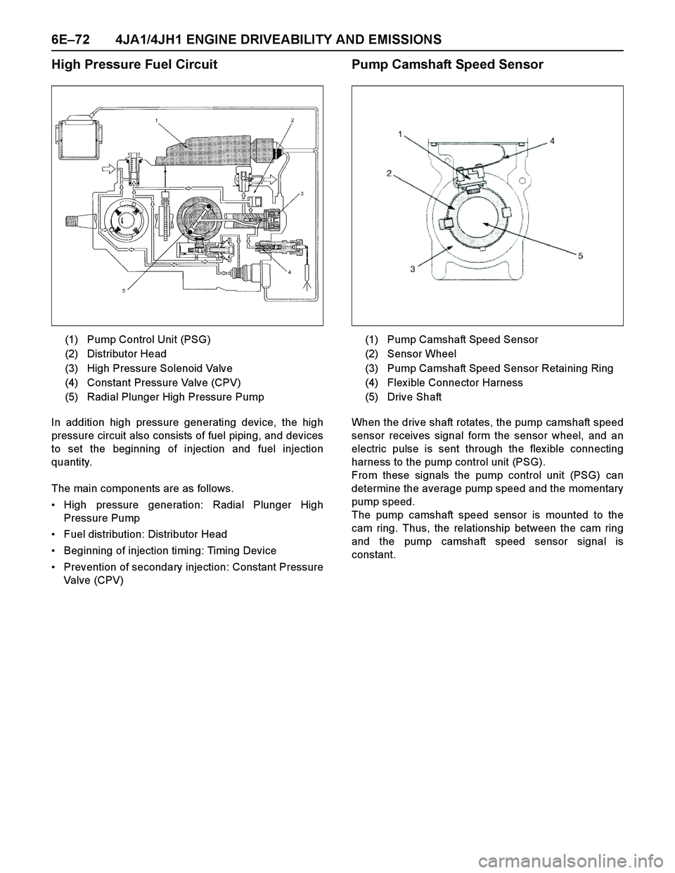
High Pressure Fuel Circuit
In addition high pressure generating device, the high
pressure circuit also consists of fuel piping, and devices
to set the beginning of injection and fuel injection
quantity.
The main components are as follows.
High pressure generation: Radial Plunger High
Pressure Pump
Fuel distribution: Distributor Head
Beginning of injection timing: Timing Device
Prevention of secondary injection: Constant Pressure
Valve (CPV)
Pump Camshaft Speed Sensor
When the drive shaft rotates, the pump camshaft speed
sensor receives signal form the sensor wheel, and an
electric pulse is sent through the flex ible connecting
harness to the pump control unit (PSG).
From these signals the pump control unit (PSG) can
determine the average pump speed and the momentary
pump speed.
The pump camshaft speed sensor is mounted to the
cam ring. Thus, the relationship between the cam ring
and the pump camshaft speed sensor signal is
constant. (1) Pump Control Unit (PSG)
(2) Distributor Head
(3) High Pressure Solenoid Valve
(4) Constant Pressure Valve (CPV)
(5) Radial Plunger High Pressure Pump
(1) Pump Camshaft Speed Sensor
(2) Sensor Wheel
(3) Pump Camshaft Speed Sensor Retaining Ring
(4) Flex ible Connector Harness
(5) Drive Shaft
Page 1445 of 4264
4JA1/4JH1 ENGINE DRIVEABILITY AND EMISSIONS 6E–73
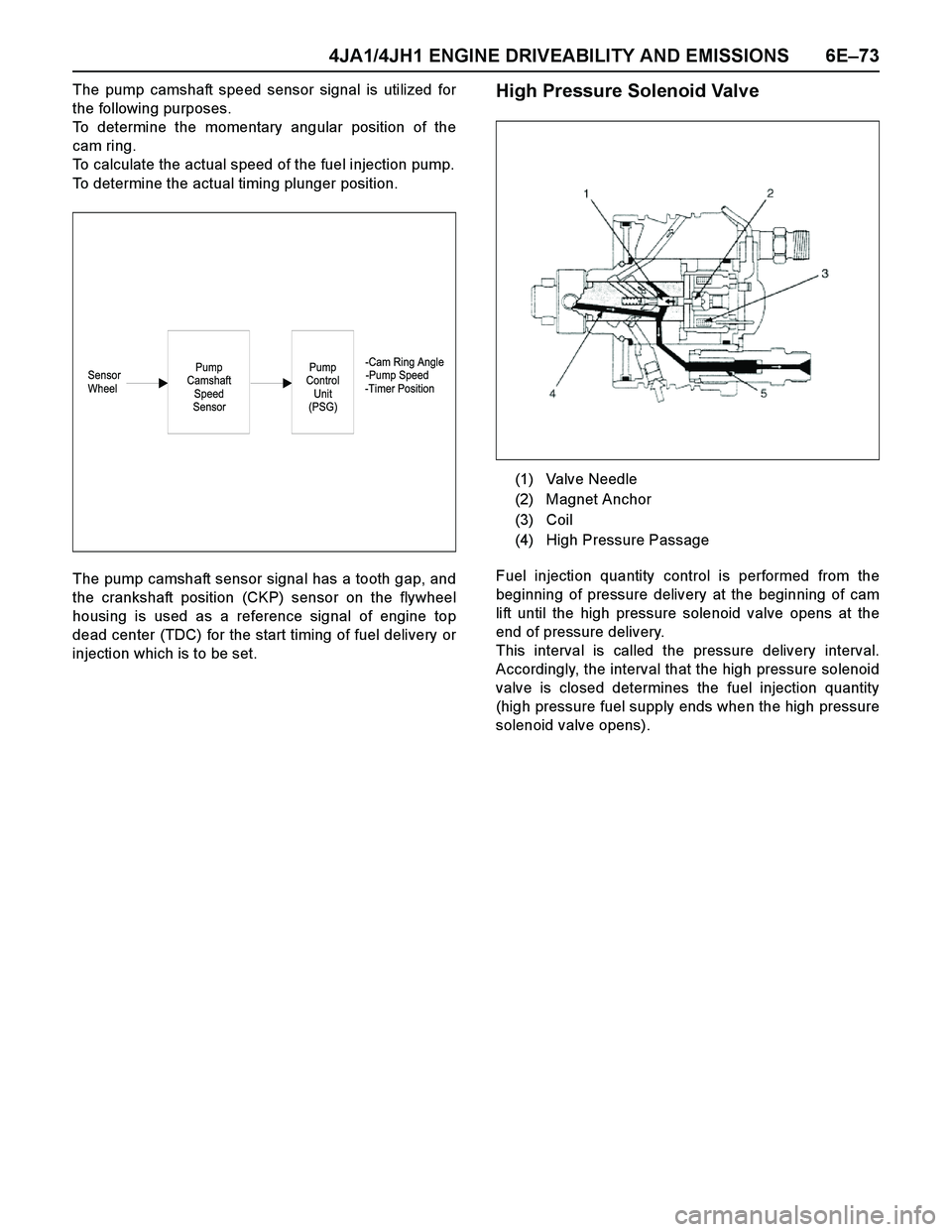
The pump camshaft speed sensor signal is utilized for
the following purposes.
To determine the momentary angular position of the
cam ring.
To calculate the actual speed of the fuel injection pump.
To determine the actual timing plunger position.
The pump camshaft sensor signal has a tooth gap, and
the crankshaft position (CKP) sensor on the flywheel
housing is used as a reference signal of engine top
dead center (TDC) for the start timing of fuel delivery or
injection which is to be set.High Pressure Solenoid Valve
Fuel injection quantity control is performed from the
beginning of pressure delivery at the beginning of cam
lift until the high pressure solenoid valve opens at the
end of pressure delivery.
This interval is called the pressure delivery interval.
Accordingly, the interval that the high pressure solenoid
valve is closed determines the fuel injection quantity
(high pressure fuel supply ends when the high pressure
solenoid valve opens).
-Cam Ring Angle
Sensor -Pump Speed
Wheel -Timer PositionPump
Control
Unit
(PSG)Pump
Camshaft
Speed
Sensor
(1) Valve Needle
(2) Magnet Anchor
(3) Coil
(4) High Pressure Passage
Page 1447 of 4264
4JA1/4JH1 ENGINE DRIVEABILITY AND EMISSIONS 6E–75
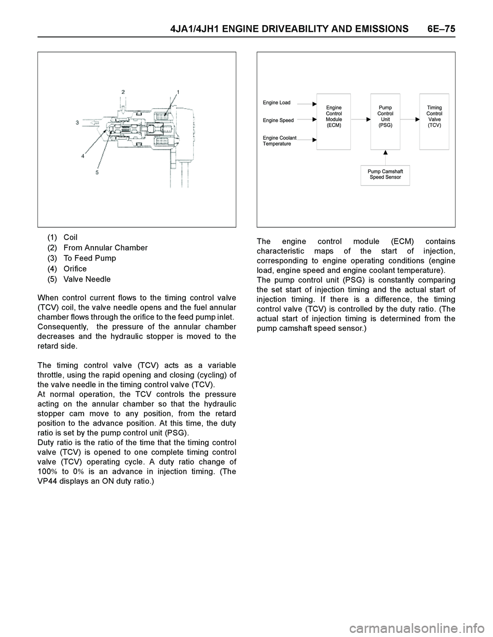
When control current flows to the timing control valve
(TCV) coil, the valve needle opens and the fuel annular
chamber flows through the orifice to the feed pump inlet.
Consequently, the pressure of the annular chamber
decreases and the hydraulic stopper is moved to the
retard side.
The timing control valve (TCV) acts as a variable
throttle, using the rapid opening and closing (cycling) of
the valve needle in the timing control valve (TCV).
At normal operation, the TCV controls the pressure
acting on the annular chamber so that the hydraulic
stopper cam move to any position, from the retard
position to the advance position. At this time, the duty
ratio is set by the pump control unit (PSG).
Duty ratio is the ratio of the time that the timing control
valve (TCV) is opened to one complete timing control
valve (TCV) operating cycle. A duty ratio change of
100% to 0% is an advance in injection timing. (The
VP44 displays an ON duty ratio.)The engine control module (ECM) contains
characteristic maps of the start of injection,
corresponding to engine operating conditions (engine
load, engine speed and engine coolant temperature).
The pump control unit (PSG) is constantly comparing
the set start of injection timing and the actual start of
injection timing. If there is a difference, the timing
control valve (TCV) is controlled by the duty ratio. (The
actual start of injection timing is determined from the
pump camshaft speed sensor.) (1) Coil
(2) From Annular Chamber
(3) To Feed Pump
(4) Orifice
(5) Valve Needle
Engine Load
Engine Speed
Engine Coolant
TemperatureEngine
Control
Module
(ECM)Pump
Control
Unit
(PSG)
Pump Camshaft
Speed Sensor
Timing
Control
Valve
(TCV)
Page 1488 of 4264
6E–116 4JA1/4JH1 ENGINE DRIVEABILITY AND EMISSIONS
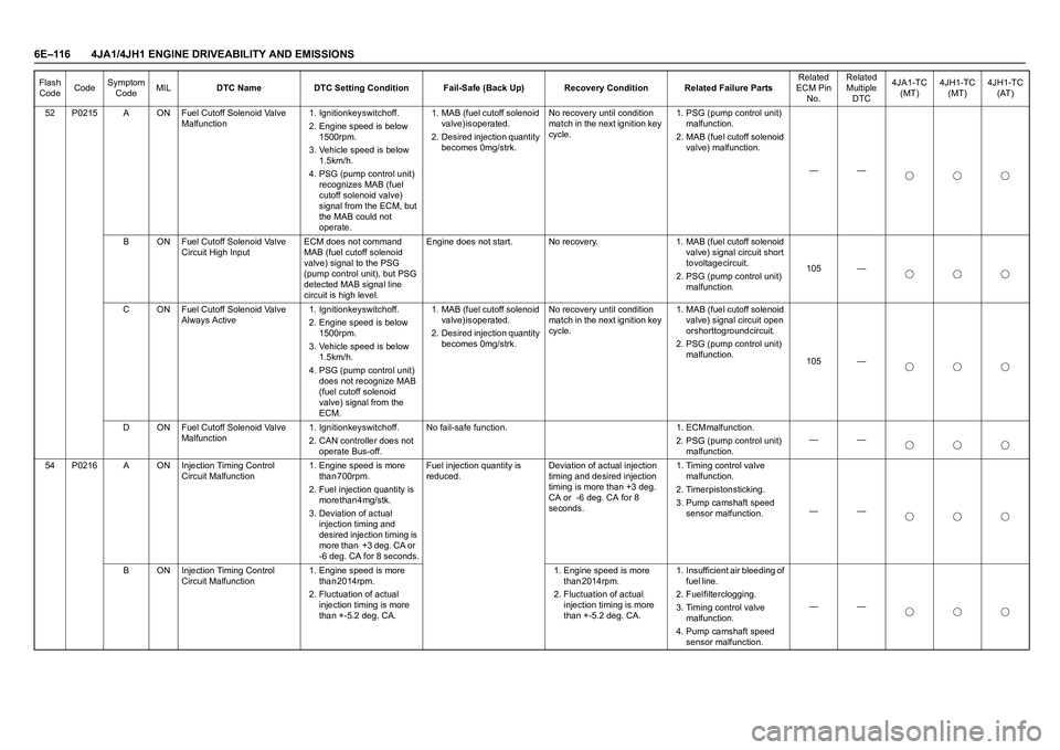
52 P0215 A ON Fuel Cutoff Solenoid Valve
Malfunction1. Ignition key switch off.
2. Engine speed is below
1 5 0 0 r p m .
3. Vehicle speed is below
1 . 5 k m / h .
4. PSG (pump control unit)
recognizes MAB (fuel
cutoff solenoid valve)
signal from the ECM, but
the MAB could not
operate. 1. MAB (fuel cutoff solenoid
v a l v e ) i s o p e r a t e d .
2. Desired injection quantity
becomes 0mg/strk.No recovery until condition
match in the next ignition key
cycle.1. PSG (pump control unit)
m a l f u n c t i o n .
2. MAB (fuel cutoff solenoid
valve) malfunction.
——
B ON Fuel Cutoff Solenoid Valve
Circuit High InputECM does not command
MAB (fuel cutoff solenoid
valve) signal to the PSG
(pump control unit), but PSG
detected MAB signal line
circuit is high level.Engine does not start. No recovery. 1. MAB (fuel cutoff solenoid
valve) signal circuit short
t o v o l t a g e c i r c u i t .
2. PSG (pump control unit)
malfunction.105 —
C ON Fuel Cutoff Solenoid Valve
Always Active1. Ignition key switch off.
2. Engine speed is below
1 5 0 0 r p m .
3. Vehicle speed is below
1 . 5 k m / h .
4. PSG (pump control unit)
does not recognize MAB
(fuel cutoff solenoid
valve) signal from the
ECM. 1. MAB (fuel cutoff solenoid
v a l v e ) i s o p e r a t e d .
2. Desired injection quantity
becomes 0mg/strk.No recovery until condition
match in the next ignition key
cycle.1. MAB (fuel cutoff solenoid
valve) signal circuit open
or short to ground circuit.
2. PSG (pump control unit)
malfunction.
105 —
D ON Fuel Cutoff Solenoid Valve
Malfunction1. Ignition key switch off.
2. CAN controller does not
operate Bus-off.N o f a i l - s a f e f u n c t i o n . 1 . E C M m a l f u n c t i o n .
2. PSG (pump control unit)
malfunction.——
54 P0216 A ON Injection Timing Control
Circuit Malfunction1. Engine speed is more
t h a n 7 0 0 r p m .
2. Fuel injection quantity is
more than 4mg/stk.
3. Deviation of actual
injection timing and
desired injection timing is
more than +3 deg. CA or
-6 deg. CA for 8 seconds.Fuel injection quantity is
reduced.Deviation of actual injection
timing and desired injection
timing is more than +3 deg.
CA or -6 deg. CA for 8
seconds.1. Timing control valve
m a l f u n c t i o n .
2 . T i m e r p i s t o n s t i c k i n g .
3. Pump camshaft speed
sensor malfunction.——
B ON Injection Timing Control
Circuit Malfunction 1. Engine speed is more
t h a n 2 0 1 4 r p m .
2. Fluctuation of actual
injection timing is more
than +-5.2 deg. CA.1. Engine speed is more
than 2014rpm.
2. Fluctuation of actual
injection timing is more
than +-5.2 deg. CA.1. Insufficient air bleeding of
f u e l l i n e .
2. Fuel filter clogging.
3. Timing control valve
m a l f u n c t i o n .
4. Pump camshaft speed
sensor malfunction. —— Flash
CodeCodeSymptom
CodeMILDTC Name DTC Setting Condition Fail-Safe (Back Up) Recovery Condition Related Failure PartsRelated
ECM Pin
No.Related
Multiple
DTC4JA1-TC
(MT)4JH1-TC
(MT)4JH1-TC
(AT)
Page 1490 of 4264
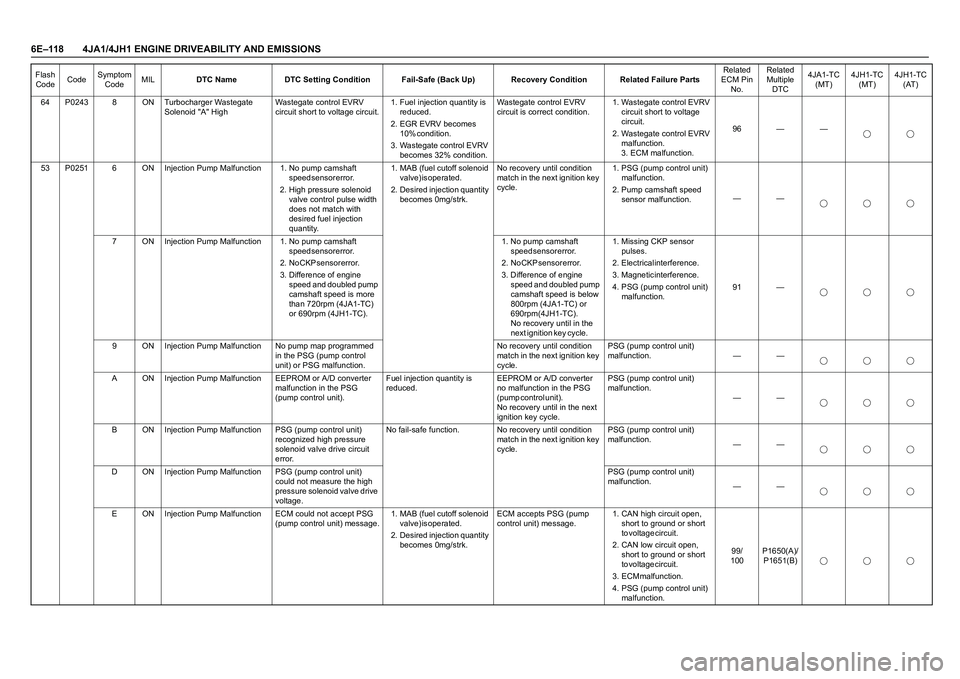
6E–118 4JA1/4JH1 ENGINE DRIVEABILITY AND EMISSIONS
64 P0243 8 ON Turbocharger Wastegate
Solenoid "A" HighWastegate control EVRV
circuit short to voltage circuit.1. Fuel injection quantity is
r e d u c e d .
2. EGR EVRV becomes
1 0 % c o n d i t i o n .
3. Wastegate control EVRV
becomes 32% condition.Wastegate control EVRV
circuit is correct condition.1. Wastegate control EVRV
circuit short to voltage
c i r c u i t .
2. Wastegate control EVRV
m a l f u n c t i o n .
3. ECM malfunction.96 — —
53 P0251 6 ON Injection Pump Malfunction 1. No pump camshaft
s p e e d s e n s o r e r r o r .
2. High pressure solenoid
valve control pulse width
does not match with
desired fuel injection
quantity. 1. MAB (fuel cutoff solenoid
v a l v e ) i s o p e r a t e d .
2. Desired injection quantity
becomes 0mg/strk.No recovery until condition
match in the next ignition key
cycle.1. PSG (pump control unit)
m a l f u n c t i o n .
2. Pump camshaft speed
sensor malfunction.——
7 ON Injection Pump Malfunction 1. No pump camshaft
s p e e d s e n s o r e r r o r .
2 . N o C K P s e n s o r e r r o r .
3. Difference of engine
speed and doubled pump
camshaft speed is more
than 720rpm (4JA1-TC)
or 690rpm (4JH1-TC). 1. No pump camshaft
s p e e d s e n s o r e r r o r .
2 . N o C K P s e n s o r e r r o r .
3. Difference of engine
speed and doubled pump
camshaft speed is below
800rpm (4JA1-TC) or
6 9 0 r p m ( 4 J H 1 - T C ) .
No recovery until in the
next ignition key cycle. 1. Missing CKP sensor
p u l s e s .
2. Electrical interference.
3. Magnetic interference.
4. PSG (pump control unit)
malfunction.91 —
9 ON Injection Pump Malfunction No pump map programmed
in the PSG (pump control
unit) or PSG malfunction.No recovery until condition
match in the next ignition key
cycle.PSG (pump control unit)
malfunction. — —
A ON Injection Pump Malfunction EEPROM or A/D converter
malfunction in the PSG
(pump control unit).Fuel injection quantity is
reduced.EEPROM or A/D converter
no malfunction in the PSG
( p u m p c o n t r o l u n i t ) .
No recovery until in the next
ignition key cycle.PSG (pump control unit)
malfunction.
——
B ON Injection Pump Malfunction PSG (pump control unit)
recognized high pressure
solenoid valve drive circuit
error.No fail-safe function. No recovery until condition
match in the next ignition key
cycle.PSG (pump control unit)
malfunction.
——
D ON Injection Pump Malfunction PSG (pump control unit)
could not measure the high
pressure solenoid valve drive
voltage.PSG (pump control unit)
malfunction.
——
E ON Injection Pump Malfunction ECM could not accept PSG
(pump control unit) message.1. MAB (fuel cutoff solenoid
v a l v e ) i s o p e r a t e d .
2. Desired injection quantity
becomes 0mg/strk.ECM accepts PSG (pump
control unit) message.1. CAN high circuit open,
short to ground or short
t o v o l t a g e c i r c u i t .
2. CAN low circuit open,
short to ground or short
t o v o l t a g e c i r c u i t .
3 . E C M m a l f u n c t i o n .
4. PSG (pump control unit)
malfunction.9 9 /
100P1650(A)/
P1651(B) Flash
CodeCodeSymptom
CodeMILDTC Name DTC Setting Condition Fail-Safe (Back Up) Recovery Condition Related Failure PartsRelated
ECM Pin
No.Related
Multiple
DTC4JA1-TC
(MT)4JH1-TC
(MT)4JH1-TC
(AT)
Page 1491 of 4264
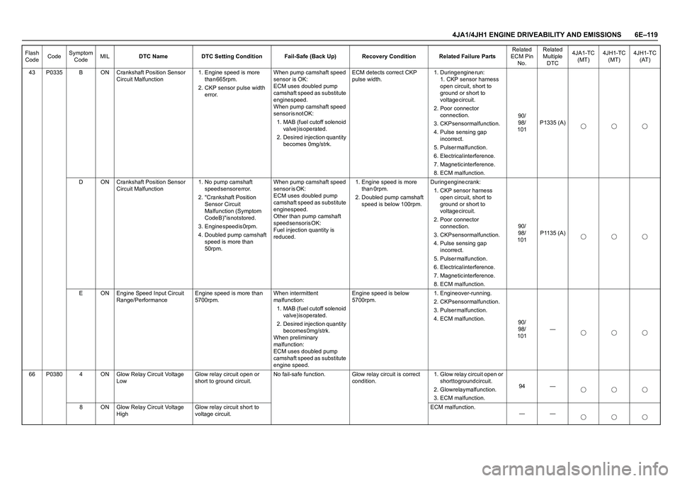
4JA1/4JH1 ENGINE DRIVEABILITY AND EMISSIONS 6E–119
43 P0335 B ON Crankshaft Position Sensor
Circuit Malfunction1. Engine speed is more
t h a n 6 6 5 r p m .
2. CKP sensor pulse width
error.When pump camshaft speed
sensor is OK:
ECM uses doubled pump
camshaft speed as substitute
engine speed.
When pump camshaft speed
s e n s o r i s n o t O K :
1. MAB (fuel cutoff solenoid
v a l v e ) i s o p e r a t e d .
2. Desired injection quantity
becomes 0mg/strk. ECM detects correct CKP
pulse width.1 . D u r i n g e n g i n e r u n :
1. CKP sensor harness
open circuit, short to
ground or short to
voltage circuit.
2. Poor connector
c o n n e c t i o n .
3. CKP sensor malfunction.
4. Pulse sensing gap
i n c o r r e c t .
5 . P u l s e r m a l f u n c t i o n .
6. Electrical interference.
7. Magnetic interference.
8. ECM malfunction.9 0 /
9 8 /
101P1335 (A)
D ON Crankshaft Position Sensor
Circuit Malfunction1. No pump camshaft
s p e e d s e n s o r e r r o r .
2. "Crankshaft Position
Sensor Circuit
Malfunction (Symptom
Code B)" is not stored.
3 . E n g i n e s p e e d i s 0 r p m .
4. Doubled pump camshaft
speed is more than
50rpm.When pump camshaft speed
s e n s o r i s O K :
ECM uses doubled pump
camshaft speed as substitute
engine speed.
Other than pump camshaft
s p e e d s e n s o r i s O K :
Fuel injection quantity is
reduced.1. Engine speed is more
than 0rpm.
2. Doubled pump camshaft
speed is below 100rpm.During engine crank:
1. CKP sensor harness
open circuit, short to
ground or short to
voltage circuit.
2. Poor connector
c o n n e c t i o n .
3. CKP sensor malfunction.
4. Pulse sensing gap
i n c o r r e c t .
5 . P u l s e r m a l f u n c t i o n .
6. Electrical interference.
7. Magnetic interference.
8. ECM malfunction.9 0 /
9 8 /
101P1135 (A)
E ON Engine Speed Input Circuit
Range/PerformanceEngine speed is more than
5700rpm.When intermittent
malfunction:
1. MAB (fuel cutoff solenoid
v a l v e ) i s o p e r a t e d .
2. Desired injection quantity
b e c o m e s 0 m g / s t r k .
When preliminary
malfunction:
ECM uses doubled pump
camshaft speed as substitute
engine speed.Engine speed is below
5700rpm.1. Engine over-running.
2. CKP sensor malfunction.
3 . P u l s e r m a l f u n c t i o n .
4. ECM malfunction.
9 0 /
9 8 /
101—
66 P0380 4 ON Glow Relay Circuit Voltage
LowGlow relay circuit open or
short to ground circuit.No fail-safe function. Glow relay circuit is correct
condition.1. Glow relay circuit open or
short to ground circuit.
2. Glow relay malfunction.
3. ECM malfunction.94 —
8 ON Glow Relay Circuit Voltage
HighGlow relay circuit short to
voltage circuit.ECM malfunction.
—— Flash
CodeCodeSymptom
CodeMILDTC Name DTC Setting Condition Fail-Safe (Back Up) Recovery Condition Related Failure PartsRelated
ECM Pin
No.Related
Multiple
DTC4JA1-TC
(MT)4JH1-TC
(MT)4JH1-TC
(AT)
Page 1497 of 4264
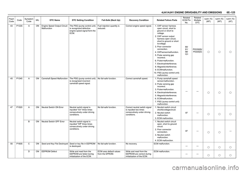
4JA1/4JH1 ENGINE DRIVEABILITY AND EMISSIONS 6E–125
43 P1335 A ON Engine Speed Output Circuit
MalfunctionThe PSG (pump control unit)
is recognized defective
engine speed signal form the
ECM.Fuel injection quantity is
reduced.Correct engine speed signal. 1. CKP sensor harness
open circuit, short to
ground or short to
voltage.
2. CKP sensor output
harness open circuit,
short to ground or short
t o v o l t a g e .
3. Poor connector
c o n n e c t i o n .
4. CKP sensor malfunction.
5. Pulse sensing gap
i n c o r r e c t .
6 . P u l s e r m a l f u n c t i o n .
7. Electrical interference.
8. Magnetic interference.
9. ECM malfunction.
10. PSG (pump control unit)
malfunction.9 0 /
9 1 /
9 8 /
101P0335(B)/
P0335(D)
45 P1345 A ON Camshaft Speed Malfunction The PSG (pump control unit)
is recognized incorrect
camshaft speed signal.No fail-safe function. Correct camshaft speed. 1. Pump camshaft speed
s e n s o r m a l f u n c t i o n .
2. Pulse sensing gap
i n c o r r e c t .
3 . P u l s e r m a l f u n c t i o n .
4. Electrical interference.
5. Magnetic interference.
6. ECM malfunction.
7. PSG (pump control unit)
malfunction.——
47 P1520 A ON Neutral Switch ON Error Neutral switch signal is
inputted "On" three times
consecutively under driving
conditions.No fail-safe function. Correct neutral switch signal
is inputted two times
consecutively under driving
conditions.1. Neutral switch circuit
short to voltage circuit.
2. Neutral switch
m a l f u n c t i o n .
3. ECM malfunction.87 —
B ON Neutral Switch OFF Error Neutral switch signal is
inputted "Off" three times
consecutively under driving
conditions.1. Neutral switch circuit
open, short to ground
c i r c u i t .
2. Poor connector
c o n n e c t i o n .
3. Neutral switch
m a l f u n c t i o n .
4. ECM malfunction.87 — —
55 P1605 C ON Seed and Key File Destroyed Seed or key file in EEPROM
is destroyed.No fail-safe function. No recovery. ECM malfunction.
——
D ON EEPROM Defect Write and read from the
EEPROM are failed during
initialization of the ECM.ECM uses default values
from the EPROM.Write and read from the
EEPROM are correct during
initialization of the ECM.ECM malfunction.
—— Flash
CodeCodeSymptom
CodeMILDTC Name DTC Setting Condition Fail-Safe (Back Up) Recovery Condition Related Failure PartsRelated
ECM Pin
No.Related
Multiple
DTC4JA1-TC
(MT)4JH1-TC
(MT)4JH1-TC
(AT)
Page 1551 of 4264
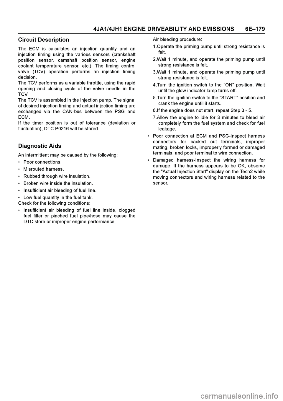
4JA1/4JH1 ENGINE DRIVEABILITY AND EMISSIONS 6E–179
Circuit Description
The ECM is calculates an injection quantity and an
injection timing using the various sensors (crankshaft
position sensor, camshaft position sensor, engine
coolant temperature sensor, etc.). The timing control
valve (TCV) operation performs an injection timing
decision.
The TCV performs as a variable throttle, using the rapid
opening and closing cycle of the valve needle in the
TCV.
The TCV is assembled in the injection pump. The signal
of desired injection timing and actual injection timing are
ex changed via the CAN-bus between the PSG and
ECM.
If the timer position is out of tolerance (deviation or
fluctuation), DTC P0216 will be stored.
Diagnostic Aids
An intermittent may be caused by the following:
Poor connections.
Misrouted harness.
Rubbed through wire insulation.
Broken wire inside the insulation.
Insufficient air bleeding of fuel line.
Low fuel quantity in the fuel tank.
Check for the following conditions:
Insufficient air bleeding of fuel line inside, clogged
fuel filter or pinched fuel pipe/hose may cause the
DTC store or improper engine performance.Air bleeding procedure:
1.Operate the priming pump until strong resistance is
felt.
2.Wait 1 minute, and operate the priming pump until
strong resistance is felt.
3.Wait 1 minute, and operate the priming pump until
strong resistance is felt.
4.Turn the ignition switch to the "ON" position. Wait
until the glow indicator lamp turns off.
5.Turn the ignition switch to the "START" position and
crank the engine until it starts.
6.If the engine does not start, repeat Step 3 - 5.
7.Allow the engine to idle for 3 minutes to bleed air
completely form the fuel system and check for fuel
leakage.
Poor connection at ECM and PSG-Inspect harness
connectors for backed out terminals, improper
mating, broken locks, improperly formed or damaged
terminals, and poor terminal to wire connection.
Damaged harness-Inspect the wiring harness for
damage. If the harness appears to be OK, observe
the "Actual Injection Start" display on the Tech2 while
moving connectors and wiring harness related to the
sensor.