2004 ISUZU TF SERIES Camshaft
[x] Cancel search: CamshaftPage 1241 of 4264
ENGINE MECHANICAL 6A – 101
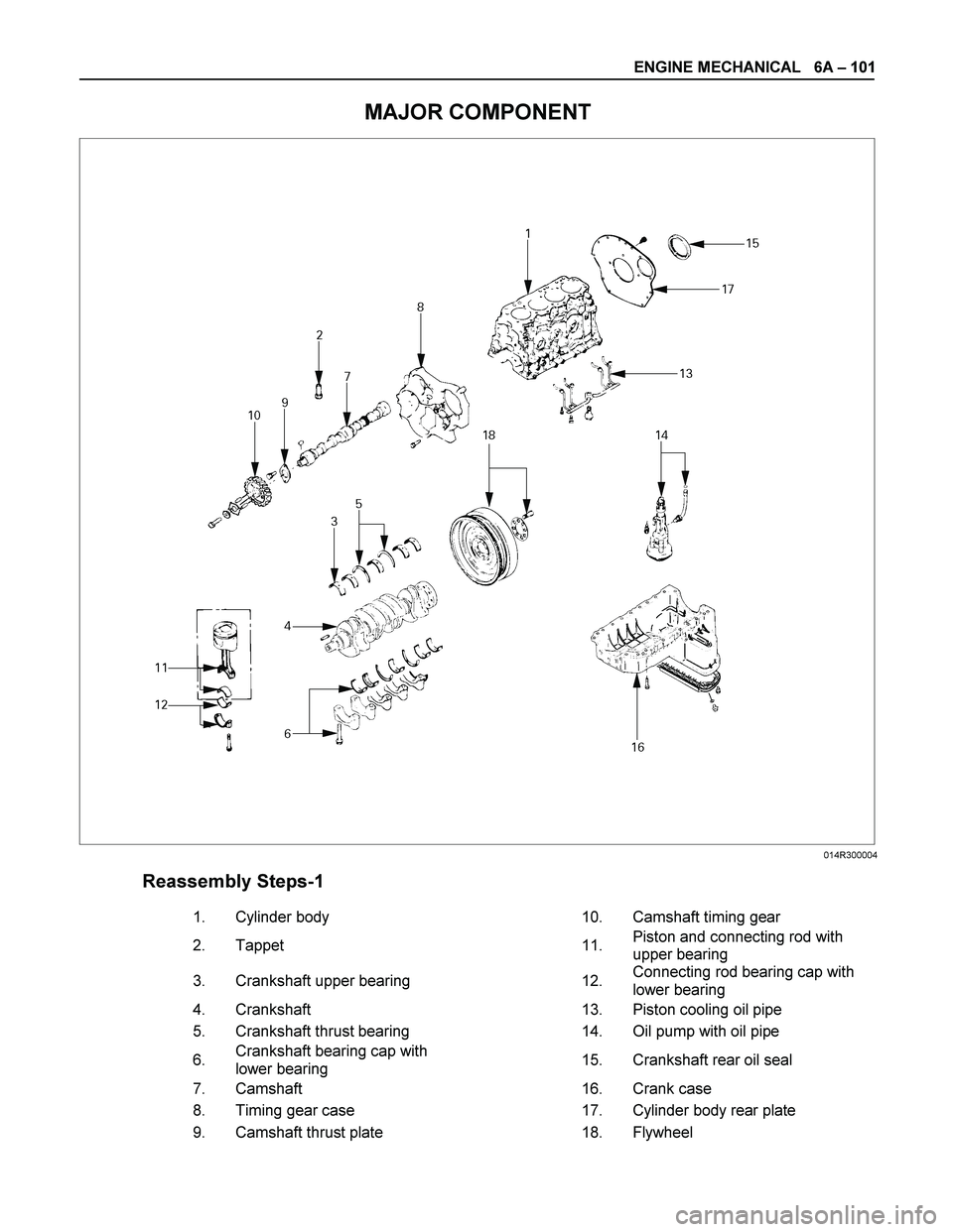
MAJOR COMPONENT
Reassembly Steps-1
1.
Cylinder body 10.
Camshaft timing gear
2.
Tappet 11. Piston and connecting rod with
upper bearing
3.
Crankshaft upper bearing 12. Connecting rod bearing cap with
lower bearing
4.
Crankshaft 13.
Piston cooling oil pipe
5.
Crankshaft thrust bearing 14.
Oil pump with oil pipe
6. Crankshaft bearing cap with
lower bearing 15.
Crankshaft rear oil seal
7.
Camshaft 16.
Crank case
8.
Timing gear case 17.
Cylinder body rear plate
9.
Camshaft thrust plate 18.
Flywheel
014R300004
Page 1244 of 4264
6A – 104 ENGINE MECHANICAL
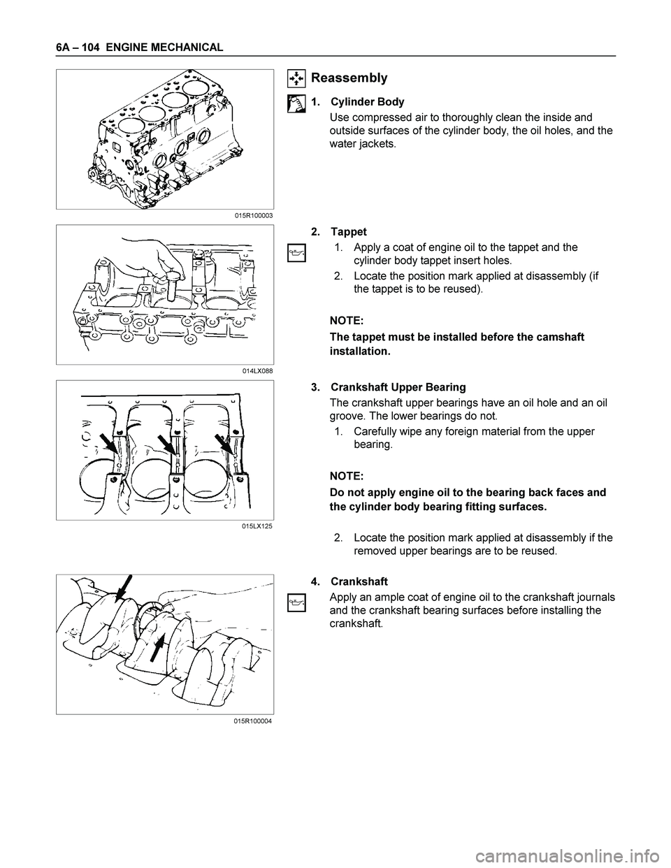
Reassembly
1. Cylinder Body
Use compressed air to thoroughly clean the inside and
outside surfaces of the cylinder body, the oil holes, and the
water jackets.
2. Tappet
1. Apply a coat of engine oil to the tappet and the
cylinder body tappet insert holes.
2. Locate the position mark applied at disassembly (if
the tappet is to be reused).
NOTE:
The tappet must be installed before the camshaft
installation.
3. Crankshaft Upper Bearing
The crankshaft upper bearings have an oil hole and an oil
groove. The lower bearings do not.
1. Carefully wipe any foreign material from the upper
bearing.
NOTE:
Do not apply engine oil to the bearing back faces and
the cylinder body bearing fitting surfaces.
2. Locate the position mark applied at disassembly if the
removed upper bearings are to be reused.
4. Crankshaft
Apply an ample coat of engine oil to the crankshaft journals
and the crankshaft bearing surfaces before installing the
crankshaft.
015R100004015R100003
014LX088
015LX125
Page 1246 of 4264
6A – 106 ENGINE MECHANICAL
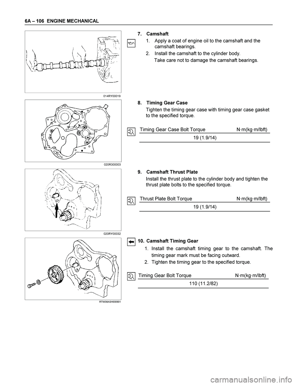
7. Camshaft
1. Apply a coat of engine oil to the camshaft and the
camshaft bearings.
2. Install the camshaft to the cylinder body.
Take care not to damage the camshaft bearings.
8. Timing Gear Case
Tighten the timing gear case with timing gear case gasket
to the specified torque.
Timing Gear Case Bolt Torque N·m(kg·m/lbft)
19 (1.9/14)
9. Camshaft Thrust Plate
Install the thrust plate to the cylinder body and tighten the
thrust plate bolts to the specified torque.
Thrust Plate Bolt Torque N·m(kg·m/lbft)
19 (1.9/14)
RTW36ASH000901
10. Camshaft Timing Gear
1. Install the camshaft timing gear to the camshaft. The
timing gear mark must be facing outward.
2. Tighten the timing gear to the specified torque.
Timing Gear Bolt Torque N·m(kg·m/lbft)
110 (11.2/82)
014RY00019
020R300003
020RY00032
Page 1251 of 4264
ENGINE MECHANICAL 6A – 111
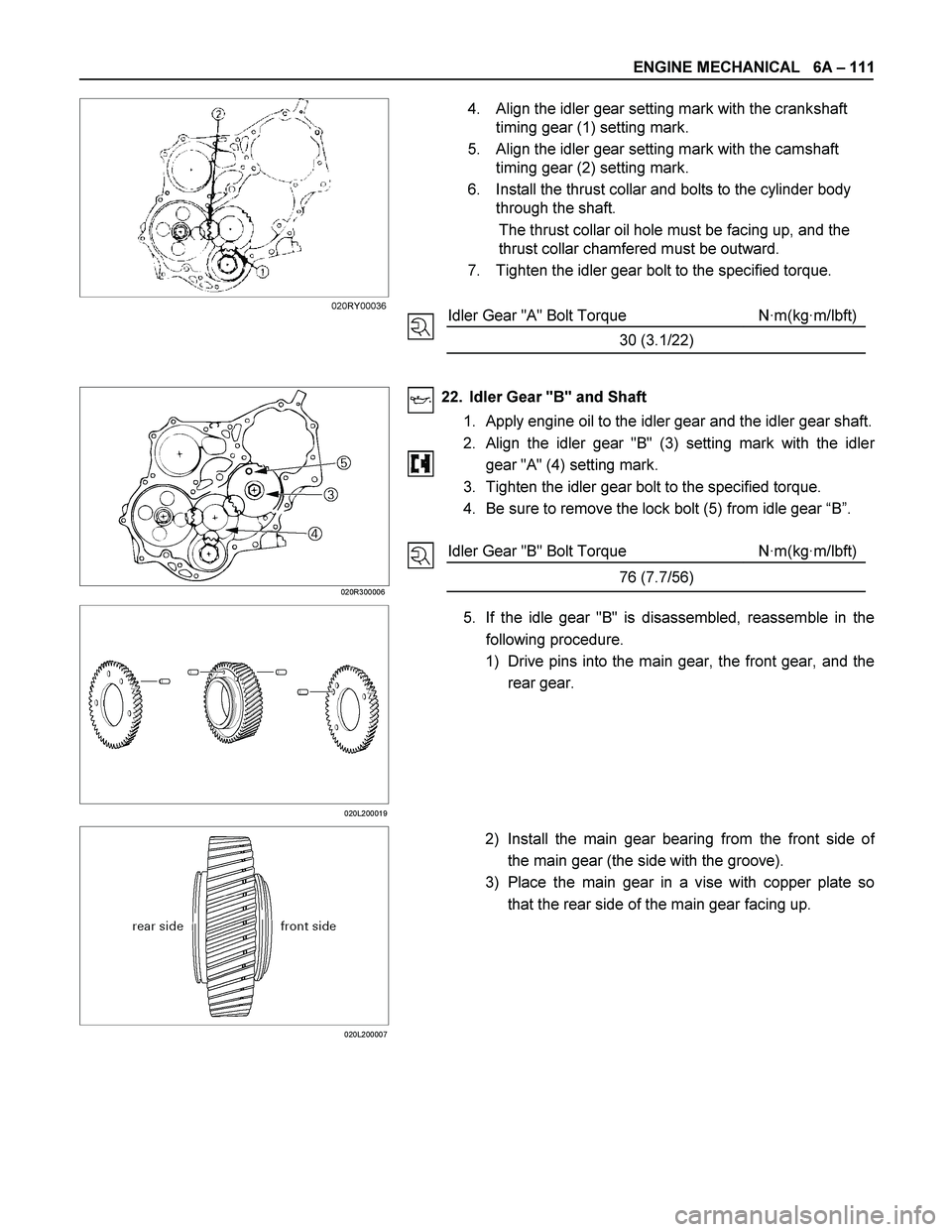
4. Align the idler gear setting mark with the crankshaft
timing gear (1) setting mark.
5. Align the idler gear setting mark with the camshaft
timing gear (2) setting mark.
6. Install the thrust collar and bolts to the cylinder body
through the shaft.
The thrust collar oil hole must be facing up, and the
thrust collar chamfered must be outward.
7. Tighten the idler gear bolt to the specified torque.
Idler Gear "A" Bolt Torque N·m(kg·m/lbft)
30 (3.1/22)
020R300006
22. Idler Gear "B" and Shaft
1. Apply engine oil to the idler gear and the idler gear shaft.
2.
Align the idler gear "B" (3) setting mark with the idler
gear "A" (4) setting mark.
3. Tighten the idler gear bolt to the specified torque.
4. Be sure to remove the lock bolt (5) from idle gear “B”.
Idler Gear "B" Bolt Torque N·m(kg·m/lbft)
76 (7.7/56)
020L200019
5. If the idle gear "B" is disassembled, reassemble in the
following procedure.
1) Drive pins into the main gear, the front gear, and the
rear gear.
020L200007
2) Install the main gear bearing from the front side of
the main gear (the side with the groove).
3) Place the main gear in a vise with copper plate so
that the rear side of the main gear facing up.
020RY00036
Page 1278 of 4264
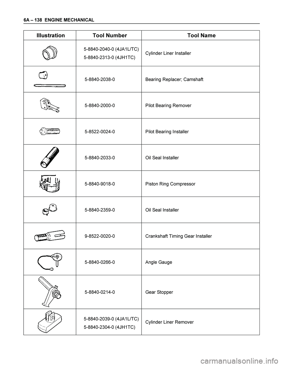
6A – 138 ENGINE MECHANICAL
Illustration Tool Number Tool Name
5-8840-2040-0 (4JA1L/TC)
5-8840-2313-0 (4JH1TC) Cylinder Liner Installer
5-8840-2038-0 Bearing Replacer; Camshaft
5-8840-2000-0 Pilot Bearing Remover
5-8522-0024-0 Pilot Bearing Installer
5-8840-2033-0 Oil Seal Installer
5-8840-9018-0 Piston Ring Compressor
5-8840-2359-0 Oil Seal Installer
9-8522-0020-0 Crankshaft Timing Gear Installer
5-8840-0266-0 Angle Gauge
5-8840-0214-0 Gear Stopper
5-8840-2039-0 (4JA1L/TC)
5-8840-2304-0 (4JH1TC) Cylinder Liner Remover
Page 1373 of 4264
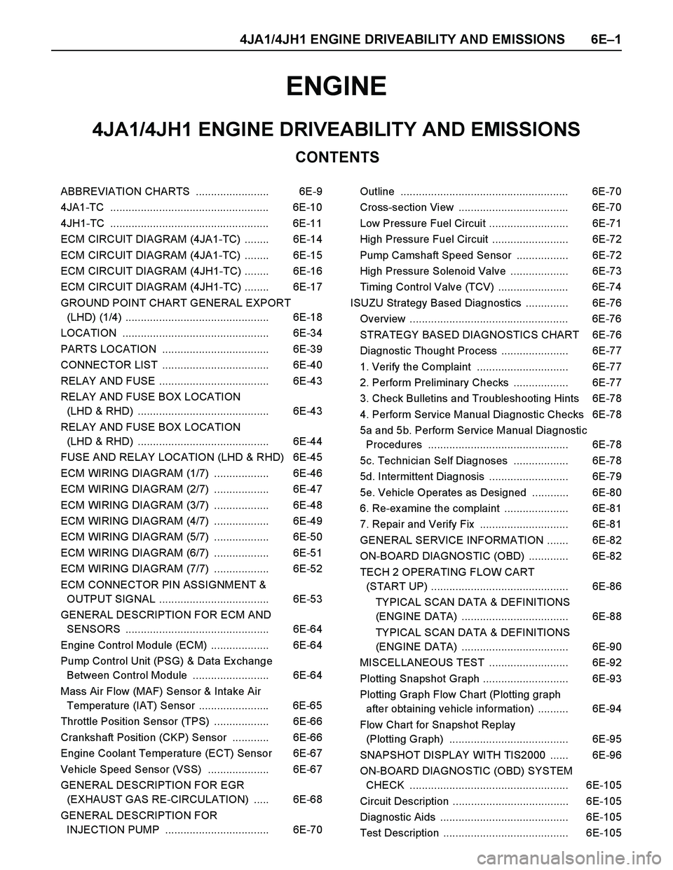
4JA1/4JH1 ENGINE DRIVEABILITY AND EMISSIONS 6E–1
ENGINE
CONTENTS
4JA1/4JH1 ENGINE DRIVEABILITY AND EMISSIONS
ABBREVIATION CHARTS ........................ 6E-9
4JA1-TC .................................................... 6E-10
4JH1-TC .................................................... 6E-11
ECM CIRCUIT DIAGRAM (4JA1-TC) ........ 6E-14
ECM CIRCUIT DIAGRAM (4JA1-TC) ........ 6E-15
ECM CIRCUIT DIAGRAM (4JH1-TC) ........ 6E-16
ECM CIRCUIT DIAGRAM (4JH1-TC) ........ 6E-17
GROUND POINT CHART GENERAL EXPORT
(LHD) (1/4) ............................................... 6E-18
LOCATION ................................................ 6E-34
PARTS LOCATION ................................... 6E-39
CONNECTOR LIST ................................... 6E-40
RELAY AND FUSE .................................... 6E-43
RELAY AND FUSE BOX LOCATION
(LHD & RHD) ........................................... 6E-43
RELAY AND FUSE BOX LOCATION
(LHD & RHD) ........................................... 6E-44
FUSE AND RELAY LOCATION (LHD & RHD) 6E-45
ECM WIRING DIAGRAM (1/7) .................. 6E-46
ECM WIRING DIAGRAM (2/7) .................. 6E-47
ECM WIRING DIAGRAM (3/7) .................. 6E-48
ECM WIRING DIAGRAM (4/7) .................. 6E-49
ECM WIRING DIAGRAM (5/7) .................. 6E-50
ECM WIRING DIAGRAM (6/7) .................. 6E-51
ECM WIRING DIAGRAM (7/7) .................. 6E-52
ECM CONNECTOR PIN ASSIGNMENT &
OUTPUT SIGNAL .................................... 6E-53
GENERAL DESCRIPTION FOR ECM AND
SENSORS ............................................... 6E-64
Engine Control Module (ECM) ................... 6E-64
Pump Control Unit (PSG) & Data Ex change
Between Control Module ......................... 6E-64
Mass Air Flow (MAF) Sensor & Intake Air
Temperature (IAT) Sensor ....................... 6E-65
Throttle Position Sensor (TPS) .................. 6E-66
Crankshaft Position (CKP) Sensor ............ 6E-66
Engine Coolant Temperature (ECT) Sensor 6E-67
Vehicle Speed Sensor (VSS) .................... 6E-67
GENERAL DESCRIPTION FOR EGR
(EXHAUST GAS RE-CIRCULATION) ..... 6E-68
GENERAL DESCRIPTION FOR
INJECTION PUMP .................................. 6E-70Outline ....................................................... 6E-70
Cross-section View .................................... 6E-70
Low Pressure Fuel Circuit .......................... 6E-71
High Pressure Fuel Circuit ......................... 6E-72
Pump Camshaft Speed Sensor ................. 6E-72
High Pressure Solenoid Valve ................... 6E-73
Timing Control Valve (TCV) ....................... 6E-74
ISUZU Strategy Based Diagnostics .............. 6E-76
Overview .................................................... 6E-76
STRATEGY BASED DIAGNOSTICS CHART 6E-76
Diagnostic Thought Process ...................... 6E-77
1. Verify the Complaint .............................. 6E-77
2. Perform Preliminary Checks .................. 6E-77
3. Check Bulletins and Troubleshooting Hints 6E-78
4. Perform Service Manual Diagnostic Checks 6E-78
5a and 5b. Perform Service Manual Diagnostic
Procedures .............................................. 6E-78
5c. Technician Self Diagnoses .................. 6E-78
5d. Intermittent Diagnosis .......................... 6E-79
5e. Vehicle Operates as Designed ............ 6E-80
6. Re-examine the complaint ..................... 6E-81
7. Repair and Verify Fix ............................. 6E-81
GENERAL SERVICE INFORMATION ....... 6E-82
ON-BOARD DIAGNOSTIC (OBD) ............. 6E-82
TECH 2 OPERATING FLOW CART
(START UP) ............................................. 6E-86
TYPICAL SCAN DATA & DEFINITIONS
(ENGINE DATA) ................................... 6E-88
TYPICAL SCAN DATA & DEFINITIONS
(ENGINE DATA) ................................... 6E-90
MISCELLANEOUS TEST .......................... 6E-92
Plotting Snapshot Graph ............................ 6E-93
Plotting Graph Flow Chart (Plotting graph
after obtaining vehicle information) .......... 6E-94
Flow Chart for Snapshot Replay
(Plotting Graph) ....................................... 6E-95
SNAPSHOT DISPLAY WITH TIS2000 ...... 6E-96
ON-BOARD DIAGNOSTIC (OBD) SYSTEM
CHECK .................................................... 6E-105
Circuit Description ...................................... 6E-105
Diagnostic Aids .......................................... 6E-105
Test Description ......................................... 6E-105
Page 1379 of 4264
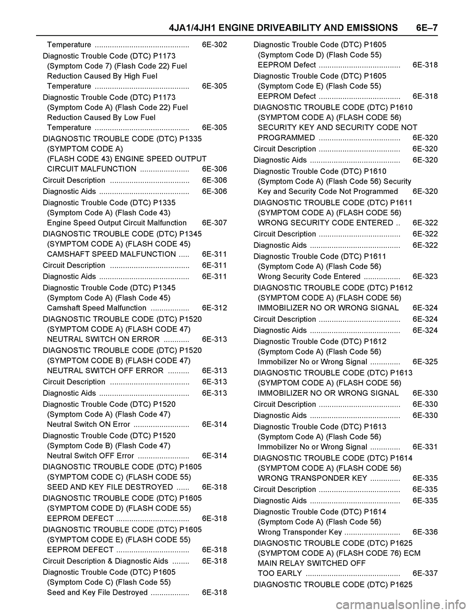
4JA1/4JH1 ENGINE DRIVEABILITY AND EMISSIONS 6E–7
Temperature ............................................ 6E-302
Diagnostic Trouble Code (DTC) P1173
(Symptom Code 7) (Flash Code 22) Fuel
Reduction Caused By High Fuel
Temperature ............................................ 6E-305
Diagnostic Trouble Code (DTC) P1173
(Symptom Code A) (Flash Code 22) Fuel
Reduction Caused By Low Fuel
Temperature ............................................ 6E-305
DIAGNOSTIC TROUBLE CODE (DTC) P1335
(SYMPTOM CODE A)
(FLASH CODE 43) ENGINE SPEED OUTPUT
CIRCUIT MALFUNCTION ....................... 6E-306
Circuit Description ..................................... 6E-306
Diagnostic Aids .......................................... 6E-306
Diagnostic Trouble Code (DTC) P1335
(Symptom Code A) (Flash Code 43)
Engine Speed Output Circuit Malfunction 6E-307
DIAGNOSTIC TROUBLE CODE (DTC) P1345
(SYMPTOM CODE A) (FLASH CODE 45)
CAMSHAFT SPEED MALFUNCTION ..... 6E-311
Circuit Description ..................................... 6E-311
Diagnostic Aids .......................................... 6E-311
Diagnostic Trouble Code (DTC) P1345
(Symptom Code A) (Flash Code 45)
Camshaft Speed Malfunction .................. 6E-312
DIAGNOSTIC TROUBLE CODE (DTC) P1520
(SYMPTOM CODE A) (FLASH CODE 47)
NEUTRAL SWITCH ON ERROR ............ 6E-313
DIAGNOSTIC TROUBLE CODE (DTC) P1520
(SYMPTOM CODE B) (FLASH CODE 47)
NEUTRAL SWITCH OFF ERROR .......... 6E-313
Circuit Description ..................................... 6E-313
Diagnostic Aids .......................................... 6E-313
Diagnostic Trouble Code (DTC) P1520
(Symptom Code A) (Flash Code 47)
Neutral Switch ON Error .......................... 6E-314
Diagnostic Trouble Code (DTC) P1520
(Symptom Code B) (Flash Code 47)
Neutral Switch OFF Error ........................ 6E-314
DIAGNOSTIC TROUBLE CODE (DTC) P1605
(SYMPTOM CODE C) (FLASH CODE 55)
SEED AND KEY FILE DESTROYED ...... 6E-318
DIAGNOSTIC TROUBLE CODE (DTC) P1605
(SYMPTOM CODE D) (FLASH CODE 55)
EEPROM DEFECT .................................. 6E-318
DIAGNOSTIC TROUBLE CODE (DTC) P1605
(SYMPTOM CODE E) (FLASH CODE 55)
EEPROM DEFECT .................................. 6E-318
Circuit Description & Diagnostic Aids ........ 6E-318
Diagnostic Trouble Code (DTC) P1605
(Symptom Code C) (Flash Code 55)
Seed and Key File Destroyed .................. 6E-318Diagnostic Trouble Code (DTC) P1605
(Symptom Code D) (Flash Code 55)
EEPROM Defect ...................................... 6E-318
Diagnostic Trouble Code (DTC) P1605
(Symptom Code E) (Flash Code 55)
EEPROM Defect ...................................... 6E-318
DIAGNOSTIC TROUBLE CODE (DTC) P1610
(SYMPTOM CODE A) (FLASH CODE 56)
SECURITY KEY AND SECURITY CODE NOT
PROGRAMMED ...................................... 6E-320
Circuit Description ...................................... 6E-320
Diagnostic Aids .......................................... 6E-320
Diagnostic Trouble Code (DTC) P1610
(Symptom Code A) (Flash Code 56) Security
Key and Security Code Not Programmed 6E-320
DIAGNOSTIC TROUBLE CODE (DTC) P1611
(SYMPTOM CODE A) (FLASH CODE 56)
WRONG SECURITY CODE ENTERED .. 6E-322
Circuit Description ...................................... 6E-322
Diagnostic Aids .......................................... 6E-322
Diagnostic Trouble Code (DTC) P1611
(Symptom Code A) (Flash Code 56)
Wrong Security Code Entered ................. 6E-323
DIAGNOSTIC TROUBLE CODE (DTC) P1612
(SYMPTOM CODE A) (FLASH CODE 56)
IMMOBILIZER NO OR WRONG SIGNAL 6E-324
Circuit Description ...................................... 6E-324
Diagnostic Aids .......................................... 6E-324
Diagnostic Trouble Code (DTC) P1612
(Symptom Code A) (Flash Code 56)
Immobilizer No or Wrong Signal .............. 6E-325
DIAGNOSTIC TROUBLE CODE (DTC) P1613
(SYMPTOM CODE A) (FLASH CODE 56)
IMMOBILIZER NO OR WRONG SIGNAL 6E-330
Circuit Description ...................................... 6E-330
Diagnostic Aids .......................................... 6E-330
Diagnostic Trouble Code (DTC) P1613
(Symptom Code A) (Flash Code 56)
Immobilizer No or Wrong Signal .............. 6E-331
DIAGNOSTIC TROUBLE CODE (DTC) P1614
(SYMPTOM CODE A) (FLASH CODE 56)
WRONG TRANSPONDER KEY .............. 6E-335
Circuit Description ...................................... 6E-335
Diagnostic Aids .......................................... 6E-335
Diagnostic Trouble Code (DTC) P1614
(Symptom Code A) (Flash Code 56)
Wrong Transponder Key .......................... 6E-336
DIAGNOSTIC TROUBLE CODE (DTC) P1625
(SYMPTOM CODE A) (FLASH CODE 76) ECM
MAIN RELAY SWITCHED OFF
TOO EARLY ............................................ 6E-337
DIAGNOSTIC TROUBLE CODE (DTC) P1625
Page 1442 of 4264
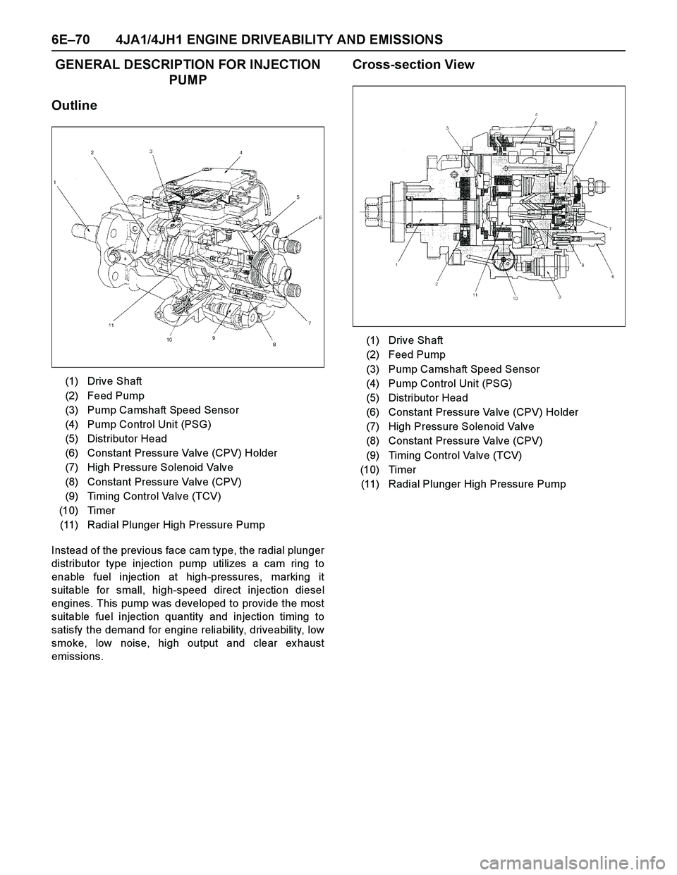
6E–70 4JA1/4JH1 ENGINE DRIVEABILITY AND EMISSIONS
GENERAL DESCRIPTION FOR INJECTION
PUMP
Outline
Instead of the previous face cam type, the radial plunger
distributor type injection pump utilizes a cam ring to
enable fuel injection at high-pressures, marking it
suitable for small, high-speed direct injection diesel
engines. This pump was developed to provide the most
suitable fuel injection quantity and injection timing to
satisfy the demand for engine reliability, driveability, low
smoke, low noise, high output and clear ex haust
emissions.
Cross-section View
(1) Drive Shaft
(2) Feed Pump
(3) Pump Camshaft Speed Sensor
(4) Pump Control Unit (PSG)
(5) Distributor Head
(6) Constant Pressure Valve (CPV) Holder
(7) High Pressure Solenoid Valve
(8) Constant Pressure Valve (CPV)
(9) Timing Control Valve (TCV)
(10) Timer
(11) Radial Plunger High Pressure Pump
(1) Drive Shaft
(2) Feed Pump
(3) Pump Camshaft Speed Sensor
(4) Pump Control Unit (PSG)
(5) Distributor Head
(6) Constant Pressure Valve (CPV) Holder
(7) High Pressure Solenoid Valve
(8) Constant Pressure Valve (CPV)
(9) Timing Control Valve (TCV)
(10) Timer
(11) Radial Plunger High Pressure Pump