Page 3197 of 4264
MANUAL TRANSMISSION 7B1-33
6. Mesh the 1st-2nd and 3rd-4th synchronizers with
both the 1st and 3rd gears (double engagement).
226RS015
This will prevent the mainshaft from turning.
7. Install the new mainshaft hub nut.
Use the mainshaft nut wrench 5-8840-2156-0 to
tighten the mainshaft nut (23) to the specified
torque.
Torque: 137 N�
�� �m (14 kg�
�� �m/101 lb�
�� �ft)
226RW214
8. Use a punch to stake the mainshaft nut (23).
226RW153
9. Install needle bearing (22), 5th block ring (21), and
5th gear (20).
10. Apply engine oil to the counter reverse gear (19) and
the reverse gear (26).
Install the counter reverse gear (19) to the counter
shaft.
The reverse gear projection must be facing the
intermediate plate.
226RW151
Page 3215 of 4264
MANUAL TRANSMISSION 7B1-51
Torque Specifications
RTW47BLF001201
About arrow mark, refer to Transmission (MUA) Installation in this section.
Page 3216 of 4264
7B1-52 MANUAL TRANSMISSION
Torque Specifications (Cont'd)
RTW47BLF000901
Page 3217 of 4264
MANUAL TRANSMISSION 7B1-53
Torque Specifications (Cont'd)
RTW47BLF000601
Page 3226 of 4264
. REFER TO THE SRS
COMPONENT AND WIRING LOCATION VIEW IN
ORDER TO DETERMINE WHET")
7B1-62 MANUAL TRANSMISSION
Service Precaution
WARNING: THIS VEHICLE HAS A SUPPLEMENTAL
RESTRAINT SYSTEM (SRS). REFER TO THE SRS
COMPONENT AND WIRING LOCATION VIEW IN
ORDER TO DETERMINE WHETHER YOU ARE
PERFORMING SERVICE ON OR NEAR THE SRS
COMPONENTS OR THE SRS WIRING. WHEN YOU
ARE PERFORMING SERVICE ON OR NEAR THE
SRS COMPONENTS OR THE SRS WIRING, REFER
TO THE SRS SERVICE INFORMATION. FAILURE TO
FOLLOW WARNINGS COULD RESULT IN POSSIBLE
AIR BAG DEPLOYMENT, PERSONAL INJURY, OR
OTHERWISE UNNEEDED SRS SYSTEM REPAIRS. CAUTION: Always use the correct fastener in the
proper location. When you replace a fastener, use
ONLY the exact part number for that application.
ISUZU will call out those fasteners that require a
replacement after removal. ISUZU will also call out
the fasteners that require thread lockers or thread
sealant. UNLESS OTHERWISE SPECIFIED, do not
use supplemental coatings (Paints, greases, or
other corrosion inhibitors) on threaded fasteners or
fastener joint interfaces. Generally, such coatings
adversely affect the fastener torque and the joint
clamping force, and may damage the fastener.
When you install fasteners, use the correct
tightening sequence and specifications. Following
these instructions can help you avoid damage to
parts and systems.
Page 3237 of 4264
.(Diesel engine)
NOTE: Tighten the lower bolt temporarily.
After installing the fuel pipe assembly, tighten the bolt to
the specified torque")
MANUAL TRANSMISSION 7B1-73
6. Install starter(16).(Diesel engine)
NOTE: Tighten the lower bolt temporarily.
After installing the fuel pipe assembly, tighten the bolt to
the specified torque.
Torque: 76 N�
�� �m (7.7 kg�
�� �m/56 lb�
�� �ft)
7. Install the rear support rubber on the transmission
and tighten the bolts to the specified torque.
Torque: 50 N�
�� �m (5.1 kg�
�� �m/37 lb�
�� �ft)
8. Install the middle part of transmission crossmember
(15) and bolts.
Tighten the nuts to the specified torque.
Torque: 67 N�
�� �m (6.8 kg�
�� �m/49 lb�
�� �ft)
9. Install engine rear mount nuts (14).
Torque: 52 N�
�� �m (5.3 kg�
�� �m/38 lb�
�� �ft)
Remove the transmission jack from transmission
side.
10. Apply grease to top hole portion of the shift fork.
Install slave cylinder (13) and tighten the bolts to the
specified torque.
Torque: 76 N�
�� �m (7.7 kg�
�� �m/56 lb�
�� �ft)
11. Install the fuel pipe brackets on the transmission.
Install the fuel pipe assembly to the fuel pipe
brackets
Torque: Bolt & Nut 76 N�
�� �m (7.7 kg�
�� �m/56 lb�
�� �ft)
Nut 37 N�
�� �m (3.8 kg�
�� �m/28 lb�
�� �ft)
Diesel engine
220R300012
Legend
(1) Bolt
(2) Nut
(3) Fuel Pipe Assembly
6VE1, C24NE
Scan-2
12. Connect transmission harness connectors and clips.
Connector: transfer neutral switch, 2W - 4W switch,
backup switch, transmission neutral switch.
810R300069
Legend
(1) Neutral Switch Connector: Transmission
(2) Backup Switch Connector
(3) Speed Sensor Connector
(4) Actuator Connector
(5) 2W - 4W Switch connector
(6) Neutral Switch Connector: Transfer
13. Apply grease (BESCO L2 or equivalent) on the
splined portion of the output shaft.
14. Connect the transfer to the transmission.
Page 3238 of 4264
7B1-74 MANUAL TRANSMISSION
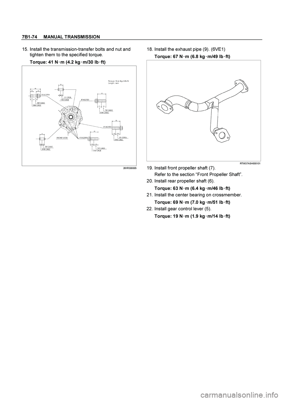
15. Install the transmission-transfer bolts and nut and
tighten them to the specified torque.
Torque: 41 N�
�� �
m (4.2 kg�
�� �
m/30 lb�
�� �
ft)
261R300005
18. Install the exhaust pipe (9). (6VE1)
Torque: 67 N�
�� �m (6.8 kg�
�� �m/49 lb�
�� �ft)
RTW37ASH000101
19. Install front propeller shaft (7).
Refer to the section “Front Propeller Shaft”.
20. Install rear propeller shaft (6).
Torque: 63 N�
�� �m (6.4 kg�
�� �m/46 lb�
�� �ft)
21. Install the center bearing on crossmember.
Torque: 69 N�
�� �m (7.0 kg�
�� �m/51 lb�
�� �ft)
22. Install gear control lever (5).
Torque: 19 N�
�� �
m (1.9 kg�
�� �
m/14 lb�
�� �
ft)
Page 3239 of 4264
MANUAL TRANSMISSION 7B1-75
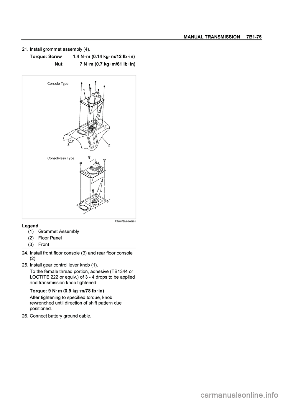
21. Install grommet assembly (4).
Torque: Screw 1.4 N�
�� �m (0.14 kg�
�� �m/12 lb�
�� �in)
Nut 7 N�
�� �m (0.7 kg�
�� �m/61 lb�
�� �in)
RTW47BMH000101
Legend
(1) Grommet Assembly
(2) Floor Panel
(3) Front
24. Install front floor console (3) and rear floor console
(2).
25. Install gear control lever knob (1).
To the female thread portion, adhesive (TB1344 or
LOCTITE 222 or equiv.) of 3 - 4 drops to be applied
and transmission knob tightened.
Torque: 9 N�
�� �m (0.9 kg�
�� �m/78 lb�
�� �in)
After tightening to specified torque, knob
rewrenched until direction of shift pattern due
positioned.
26. Connect battery ground cable.
.
226RS015
This will prevent the mainshaft from turning.
7.")
 Installation in this section.")

RTW47BLF000901")

RTW47BLF000601")