Page 3442 of 4264

3B-12 POWER-ASSISTED STEERING SYSTEM
901RW270
4. Disconnect the feed line and return line from
steering unit.
Remove the clips on the crossmember and frame.
Wire the power steering line to frame.
NOTE: Take care to prevent foreign matter from entr
y
when disconnect the power steering line.
5. Remove the power steering unit from the
crossmember.
Installation
1. Install power steering unit to crossmember.
Tighten fixing bolt and nut to specified torque.
Torque:
106 – 126 N�
�� �m (10.8 – 12.8 kg�
�� �m/78 - 93 lb ft)
Torque:
198 - 242 N�
�� �m (20.2 – 24.7 kg�
�� �m/146 - 178 lb ft)
2. Connect the feed line and return line.
Torque:
20 - 29 N�
�� �
m (2.0 – 3.0 kg�
�� �
m/14 - 22 lb ft)
3. Install tie-rod end assembly to knuckle.
Torque:
88 – 127 N�
�� �m (9.0 – 13.0 kg�
�� �m/65 - 94 lb ft)
4.
Align the setting marks on the universal joint
(applied at disassembly) with the setting marks on
the power steering unit. Connect the universal joint
assembly to the power steering unit. Temporaril
y
tighten the universal joint bolts on the universal joint
assembly side.
5. Tighten the universal joint bolts (bolts at either end
of the joint temporarily tightened in Step 1 and 2) to
the specified torque.
6. Install the stone guard.
7. Bleed the system.
Refer to Bleeding the Power Steering System in this
section.
Page 3444 of 4264

3B-14 POWER-ASSISTED STEERING SYSTEM
Tie-rod End
If looseness or play is found when checked by moving
the end of ball joint at tie-rod end, replace tie-rod end.
Tie-rod Assembly
If the resistance is insufficient or play is felt when
checked by moving the ball on the tie-rod, replace the
tie-rod assembly.
Rubber Parts
If wear or damage is found through inspection, replace
with new ones.
Reassembly
1. Install mounting rubber and dust cover (If removed).
2. Install oil line.
Torque: 10 - 15 N�
�� �m (1.0 – 1.5 kg�
�� �m/87 - 130 lb in)
3. Install tie-rod assembly with tab washer.
Apply grease to ball joint, install tie-rod and tab
washer, then tighten to specified torque.
Torque: 69 - 98 N�
�� �m (7.0 – 10.0 kg�
�� �m/51 - 72 lb ft)
After tightening, bend tab washer against width
across flat of inner ball joint.
4.
Apply a thin coat of grease to the shaft for smooth
installation. Then install bellows.
5. Install band and clip.
6. Install tie-rod end and tighten lock nut.
Torque:
92 - 104 N�
�� �m (9.4 – 10.6 kg�
�� �m/68 - 77 lb ft)
Main Data and Specifications
General Specifications
2WD 4WD
Power steering Without With
Type Rack and pinion
Rack stroke mm (in) 138 (5.43) 138 (5.43) 152 (5.98)
Steering unit
Lock to lock 4.84 3.38 3.26
Page 3445 of 4264
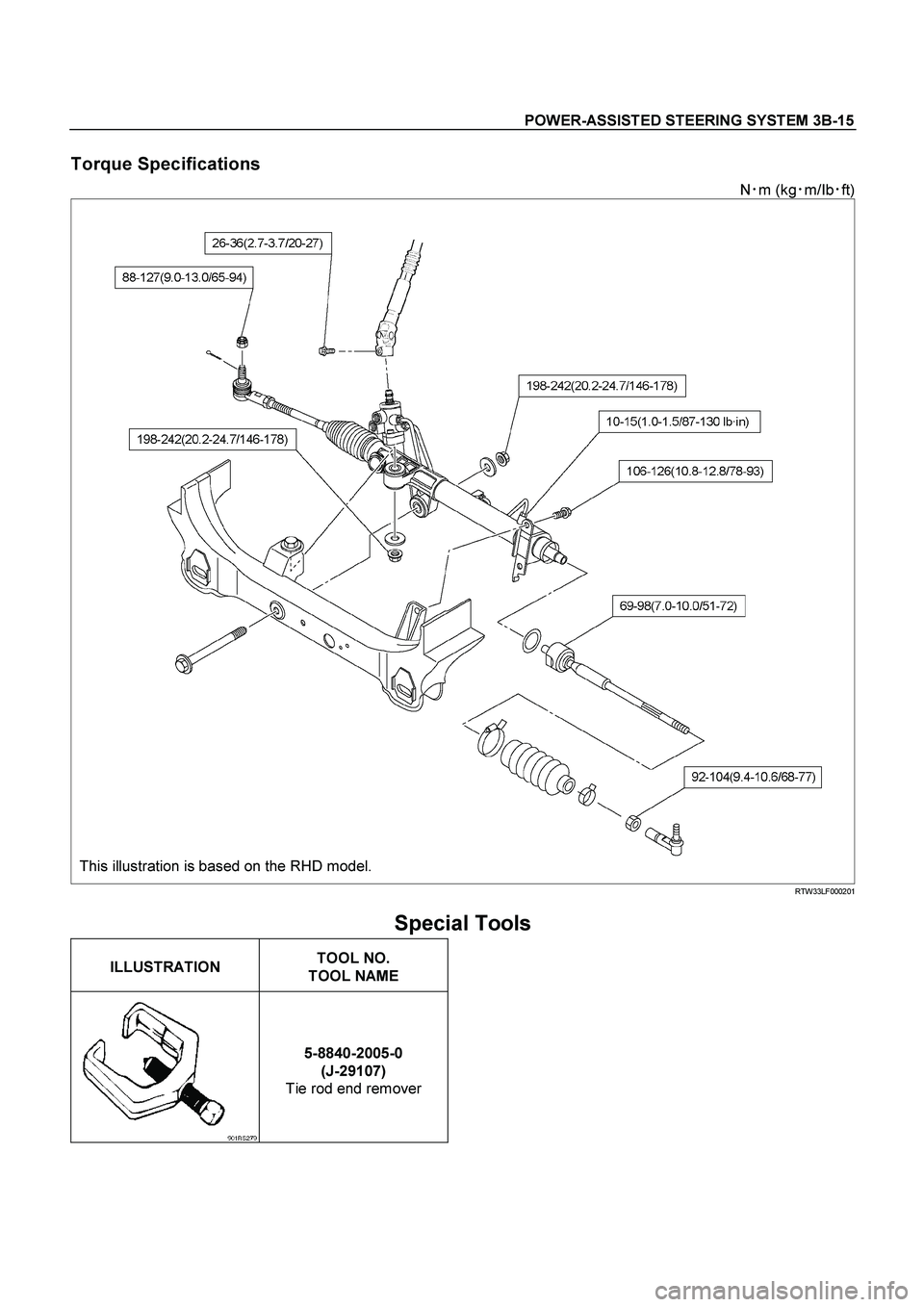
POWER-ASSISTED STEERING SYSTEM 3B-15
Torque Specifications
N�
m (kg�
m/Ib�
ft)
This illustration is based on the RHD model. RTW33LF000201
Special Tools
ILLUSTRATION
TOOL NO.
TOOL NAME
5-8840-2005-0
(J-29107)
Tie rod end remover
Page 3446 of 4264
3B-16 POWER-ASSISTED STEERING SYSTEM
Power Steering Pump
Power Steering Pump and Associated Parts (4JH1-TC, 4JA1-TC, 4JA1-L)
442R300002
Legend
(1) Pump Assembly
(2) Hose, Suction
(3) Hose, Flexible
(4) Bolt
Removal
1. Remove the drive belt.
2. Remove the pulley
3. Place a drain pan below the pump.
4. Disconnect the suction hose.
5. Disconnect the flexible hose.
6. Remove the power steering fixing bolt and remove
the pump assembly.
Installation
1. Install the pump assembly to the pump braket,
tighten the fixing bolt to the specified torque.
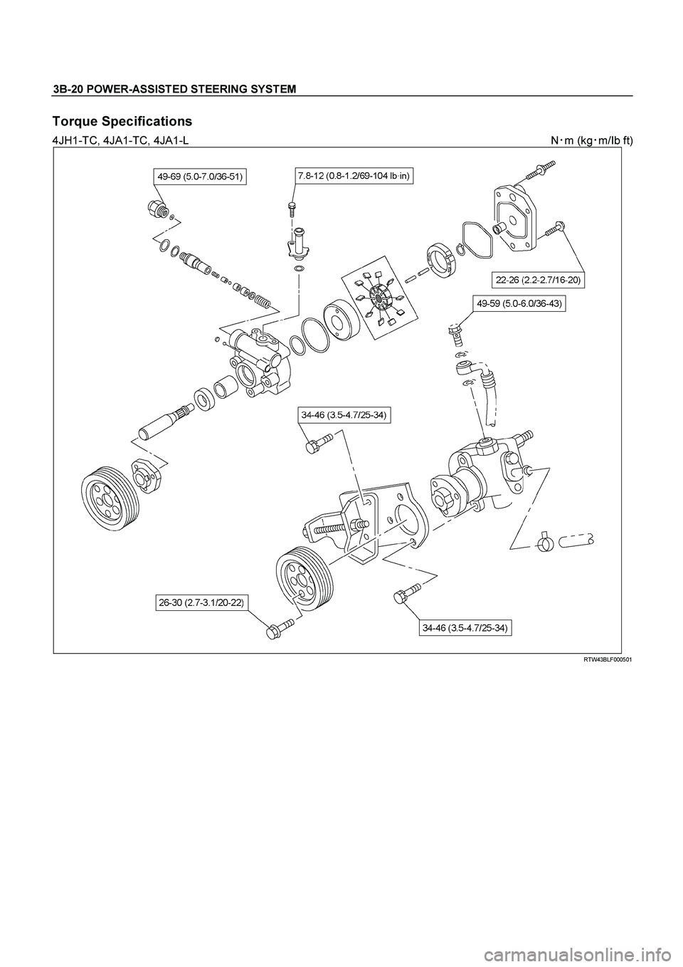
Torque: 34 - 46 N·m (3.5 – 4.7 kg·m/25 - 34 lb ft)
2. Install the flexible hose.
Tighten the eye bolt to specified torque.
Torque: 49 - 59 N·m (5.0 – 6.0 kg·m/36 - 43 lb ft)
3. Install the pulley and tighten the bolt to the specified
torque.
Torque: 26 - 30 N·m (2.7 –3.1 kg·m/20 - 22 lb ft)
4. Install the drive belt.
5. Connect the suction hose, then fill and bleed system.
Refer to Bleeding the Power Steering System in this
section.
Page 3449 of 4264

POWER-ASSISTED STEERING SYSTEM 3B-19
Reassembly
1. Install oil seal to front housing. Be sure to discard
used oil seal, and always use new parts fo
r
installation.
CAUTION: When installing the oil seal, be careful
not to damage the oil seal contacting surface of the
housing.
2. Install shaft assembly.
3. Install the vanes to roter with curved face in contac
t
with the inner wall of cam.
442RS005
4. Install roter and vanes to cam.
5. Install pin to front housing.
6. Install two new O-rings to front housing. Be sure to
discard used O-ring.
7. Install side plate.
CAUTION: When installing side plate, be careful not
to damage its inner surface. Damaged side plate
may cause poor pump performance, pump seizure
or oil leakage.
8. Install pump cartridge assembly to front housing.
9. Install snap ring to shaft end.
10. Install rear housing with a new O-ring. Be sure to
discard used O-ring. Then install bolt and tighten it
to specified torque.
Torque: 22-26 N�
�� �m (2.2-2.7kg�
�� �m/16-20 lb ft)
11. Install suction pipe with a new O-ring. Be sure to
discard used O-ring. Then install bolt and tighten it
to specified torque.
Torque: 7.8-12 N�
�� �m (0.8-1.2kg�
�� �m/69-104 lb in)
12. Install relief valve and spring.
13. Install connector with a new O-ring. Be sure to
discard used O-ring. Tighten the connector to
specified torque.
Torque: 49-69 N�
�� �m (5.0-7.0kg�
�� �m/36-51 lb ft)
Main Data and Specifications
General Specifications
Oil pump Type Vane
Operating fluid
ATF DEXRON®�
III
Page 3450 of 4264
3B-20 POWER-ASSISTED STEERING SYSTEM
Torque Specifications
4JH1-TC, 4JA1-TC, 4JA1-L N�
m (kg�
m/Ib ft)
RTW43BLF000501
Page 3451 of 4264

RTW33BLF000801
Legend
(1) Pump Assembly
(2) Hose, Suction
(3) Hose, Flexible
(4) Bolt
(5) Connecto")
POWER-ASSISTED STEERING SYSTEM 3B-21
Power Steering Pump and Associated Parts (C24SE)
RTW33BLF000801
Legend
(1) Pump Assembly
(2) Hose, Suction
(3) Hose, Flexible
(4) Bolt
(5) Connector, Pressure switch
Removal
1. Remove the drive belt.
2. Remove the pulley
3. Place a drain pan below the pump.
4. Disconnect the suction hose.
5. Disconnect the flexible hose.
6. Disconnect the oil pressure switch connector.
7. Remove the power steering fixing bolt and remove
the pump assembly.
Installation
1. Install the pump assembly to the pump braket,
tighten the fixing bolt to the specified torque.
Torque: 34-46 N·m (3.5-4.7 kg·m/25-34 lb ft)
2. Connector the oil pressure switch connector.
3. Install the flexible hose.
Tighten the eye bolt to specified torque.
Torque: 49-59 N·m (5.0-6.0 kg·m/36-43 lb ft)
4. Install the pulley and tighten the bolt to the specified
torque.
Torque: 69-88 N·m (7.0-9.0 kg·m/51-65 lb ft)
5. Install the drive belt.
6. Connect the suction hose, then fill and bleed
system.
Refer to Bleeding the Power Steering System in this
section.
Page 3454 of 4264
, which can be felt by the finger
nail. The parts with minor scores may be")
3B-24 POWER-ASSISTED STEERING SYSTEM
Side Plate
The sliding faces of parts must be free from step wear
(more than 0.01 mm), which can be felt by the finger
nail. The parts with minor scores may be reused after
lapping the face.
Valve
The sliding face of the valve must be free from burrs
and damage. The parts with minor scores may be
reused after smoothing with emery cloth (#800 or finer).
Shaft
Oil seal sliding faces must be free from a step wear
which can be felt by the finger nail. Needle bearing fitting
face must be free from damage and wear.
O-ring, Oil Seal, Retaining Ring
Be sure to discard used parts, and always use new
parts for installation. Prior to installation, lubricate all
seals and rings with power steering fluid.
Pressure Switch
Check the switch operation as follows:
With engine idling and A/C on, turn the steering wheel
fully to the left; compressor should interrupt and engine
idle speed will increase. Shut off A/C and again turn
steering fully to the left; engine idle will increase. I
f
system fails to function properly, disconnect connector
at the pressure switch and repeat system check while
testing continuity across disconnected SW connector.
Reassembly
1. Install oil seal to front housing. Be sure to discard
used oil seal, and always use new parts fo
r
installation.
CAUTION: When installing the oil seal, be careful
not to damage the oil seal contacting surface of the
housing.
2. Install shaft assembly.
3. Install the vanes to roter with curved face in contact
with the inner wall of cam.
442RS005
4. Install rotor and vanes to cam.
5. Install pin to front housing.
6. Install two new O-rings to front housing. Be sure to
discard used O-ring.
7. Install side plate.
CAUTION: When installing side plate, be careful not
to damage its inner surface. Damaged side plate
may cause poor pump performance, pump seizure
or oil leakage.
8. Install pump cartridge assembly to front housing.
9. Install snap ring to shaft end.
10. Install rear housing with a new O-ring. Be sure to
discard used O-ring. Then install bolt and tighten it
to specified torque.
Torque: 22-26 N�
�� �m (2.2-2.7 kg�
�� �m/16-20 lb ft)
11. Install suction pipe with a new O-ring. Be sure to
discard used O-ring. Then install bolt and tighten it
to specified torque.
Torque: 7.8-12 N�
�� �m (0.8-1.2 kg�
�� �m/6-9 lb ft)
12. Install relief valve and spring.
13. Install connector with a new O-ring. Be sure to
discard used O-ring. Tighten the connector to
specified torque.
Torque: 49-69 N�
�� �m (5.0-7.0 kg�
�� �m/36-51 lb ft)
14. Install pressure switch assembly and tighten it to
specified torque.
Torque: 15-20 N�
�� �m (1.5-2.0 kg�
�� �m/11-14 lb ft)

442R300002
Legend
(1) Pump Assembly
(2) Hose, Suction
(3) Hose,")