Page 3367 of 3502
FRONT SEAT
SE-111
C
D
E
F
G
H
J
K
L
MA
B
SE
8. Remove seat cushion trim and pad from seat cushion frame.
9. After removing seat cushion trim and pad, remove hog rings (non-reusable parts) to separate trim and pad
and seat heater unit.
10. Remove screws, and then remove the power seat switch.
11. Remove seat cushion bolts, and then remove seat cushion
frame.
12. Disconnect air valve connector and then, disconnect pump tube connector.
13. Remove air valve nuts, and then remove air valve.
14. Disconnect dual-lock fastener, and then air pump.
ASSEMBLY
Assemble in the reverse order of disassembly.
PIIB1948E
PIIB1950E
Page 3372 of 3502
SE-116
REAR SEAT
Removal and Installation of Seat CushionBIS0014N
REMOVAL
1. Pull plastic hook LH/RH on seat cushion bottom, and then pull seat cushion up and remove it.
2. Disconnect seat heater harness connector (only with the seat heater).
3. Remove seat cushion assembly from the vehicle.
CAUTION:
When removing and installing, use shop cloths to protect parts from damage.
INSTALLATION
Install in the reverse order of removal.
Disassembly and Assembly of Seat CushionBIS0014O
DISASSEMBLY
Remove hog rings (non-reusable parts) to separate the trim and pad and seat heater unit.
ASSEMBLY
Assembly in the reverse order of disassembly.
1. Wire 2. Cushion hook 3. Plastic hook
PIIB1951E
Page 3373 of 3502
REAR SEAT
SE-117
C
D
E
F
G
H
J
K
L
MA
B
SE
Removal and Installation of SeatbackBIS0014P
REMOVAL
1. Remove seatback bolts and seat belt anchor bolts.
2. Disconnect seat harness connector.
3. Remove seat belt finisher from seatback shoulder, and then
pass seat belt through the hole.
4. Lift up seatback assembly from underneath, and then remove it
from hook that is fixed to the vehicle.
5. Pull out center seat belt, and then remove seatback from the vehicle.
CAUTION:
When removing and installing, use shop cloths to protect parts from damage.
INSTALLATION
Install in the reverse order of removal.
1. Bolt 2. Anchor bolt
PIIB1952E
PIIA6236E
PIIA6237E
Page 3374 of 3502

BIS0014Q
DISASSEMBLY
1. Remove headrest (headrest removed and installed type seat")
SE-118
REAR SEAT
Disassembly and Assembly of Seatback (Headrest Fixed Type and Headrest
Removed and Installed Type)
BIS0014Q
DISASSEMBLY
1. Remove headrest (headrest removed and installed type seat only).
2. Remove headrest holder (headrest removed and installed type
seat only).
CAUTION:
Before installing headrest holder, check its orientation
(front/rear and right/left).
3. Remove clip, and then remove seatback mat (only with the seat heater).
4. Release armrest and remove seat back center bracket bolts,
and then remove seatback center bracket (headrest removed
and installed type seat only).
5. Remove seatback screen screws, and then remove seatback
screen.
6. Remove armrest bolts, and then remove armrest assembly from
seatback assembly.
7. Remove hog rings (non-reusable parts), and then remove seatback mat from seatback assembly. (With-
out seat heater.)
8. Remove hog rings (non-reusable parts) to separate the seatback trim and pad.
9. Remove heater control unit nuts, and then remove heater control unit (only with the seat heater).
ASSEMBLY
Assemble in the reverse order of disassembly.
PIIA1158E
PIIA6238E
PIIA6239E
Page 3412 of 3502

SRS-38
SPIRAL CABLE
7. Disconnect the horn switch connector and spiral cable connec-
tor.
NOTE:
Disconnect the horn switch connector, and then the spiral cable
connector.
CAUTION:
Do not tap or bump the steering wheel.
8. Loosen screws. While pushing upper plastic tab, remove spiral cable.
INSTALLATION
Install in the reverse order of removal.
CAUTION:
�If it is mounted in the inappropriate position, spiral cable
may be cut when performing steering operation.
�Also, with the steering linkage disconnected the cable may
snap by turning the steering wheel beyond the limited num-
ber of turns. The spiral cable can be turned counterclock-
wise about 2.5 turns from the right end position.
�Do not twist spiral cable freely or excessively after it
becomes tight (doing so may cause the cable to be torn
off).
�Secure air bag harness to the harness fixing hook.
�Check SRS air bag warning lamp to make sure that the sys-
tem works normally after finishing work.
�If SRS air bag warning lamp indicates a DTC exists, reset
with self-diagnosis and erase the memory using CONSULT-
II.
�After the operation above, if SRS air bag warning lamp still
shows a non-standard condition, perform system trouble
diagnosis again, and repair or replace the indicated compo-
nent. Refer to SRS-16, "
SRS Operation Check" .
SHIA0193E
PHIA0599E
Page 3413 of 3502

FRONT PASSENGER AIR BAG MODULE
SRS-39
C
D
E
F
G
I
J
K
L
MA
B
SRS
FRONT PASSENGER AIR BAG MODULEPFP:K8515
Removal and InstallationBHS0004G
REMOVAL
CAUTION:
�Before servicing SRS, turn the ignition switch off, disconnect both battery cables and wait at least
3 minutes.
�Always work from the side of or under front passenger air bag module.
1. Remove instrument passenger lower panel. Refer to IP-14, "
(K) Instrument Passenger Lower Panel" .
2. Disconnect front passenger air bag module connector.
3. Remove the front passenger air bag module fixing bolts.
4. Pull out and remove air bag module to instrument panel bottom so that no impact is given on passenger
air bag module.
CAUTION:
�Always place front passenger air bag module with caution
label side facing upward.
�Do not insert any foreign objects (screwdriver, etc.) into
front passenger air bag module.
�Do not disassemble front passenger air bag module.
�Do not use old bolts after removal; replace with new bolts.
�Replace front passenger air bag module if it has been
dropped or sustained an impact.
�Do not expose the front passenger air bag module to tem-
peratures exceeding 90°C (194°F).
�Do not allow oil, grease or water to come in contact with the
front passenger air bag module.
�After front passenger air bag module inflates, the instru-
ment panel assembly should be replaced.
INSTALLATION
Install in the reverse order of removal.
CAUTION:
�Always work from the side of or under front passenger air bag module.
�After the work is completed, perform self-diagnosis to make sure no malfunction is detected.
Refer to SRS-16, "
SRS Operation Check" .
PHIA0601E
PHIA0602E
SBF814E
Page 3415 of 3502
FRONT SIDE AIR BAG MODULE
SRS-41
C
D
E
F
G
I
J
K
L
MA
B
SRS
INSTALLATION
Install in the reverse order of removal.
CAUTION:
�Always work from the rear of the front side air bag module.
�After the work is completed, perform self-diagnosis to make sure no malfunction is detected.
Refer to SRS-16, "
SRS Operation Check" .
Page 3417 of 3502
SIDE CURTAIN AIR BAG MODULE
SRS-43
C
D
E
F
G
I
J
K
L
MA
B
SRS
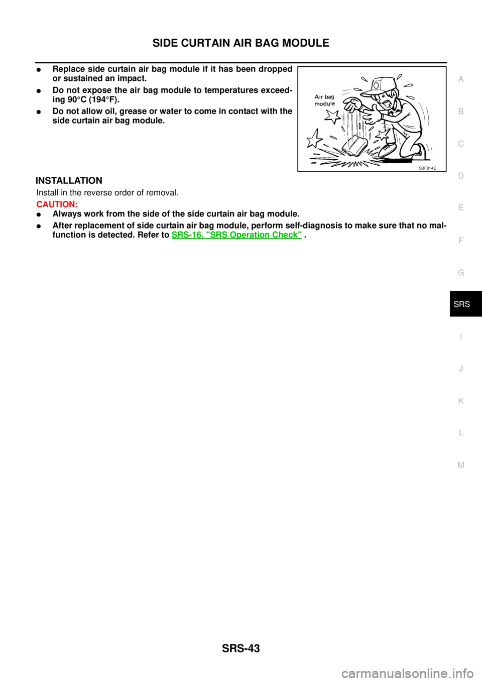
�Replace side curtain air bag module if it has been dropped
or sustained an impact.
�Do not expose the air bag module to temperatures exceed-
ing 90°C (194°F).
�Do not allow oil, grease or water to come in contact with the
side curtain air bag module.
INSTALLATION
Install in the reverse order of removal.
CAUTION:
�Always work from the side of the side curtain air bag module.
�After replacement of side curtain air bag module, perform self-diagnosis to make sure that no mal-
function is detected. Refer to SRS-16, "
SRS Operation Check" .
SBF814E
 to separat")