Page 3011 of 3502
ENGINE MAINTENANCE (VQ23DE AND VQ35DE)
MA-33
C
D
E
F
G
H
I
J
K
MA
B
MA
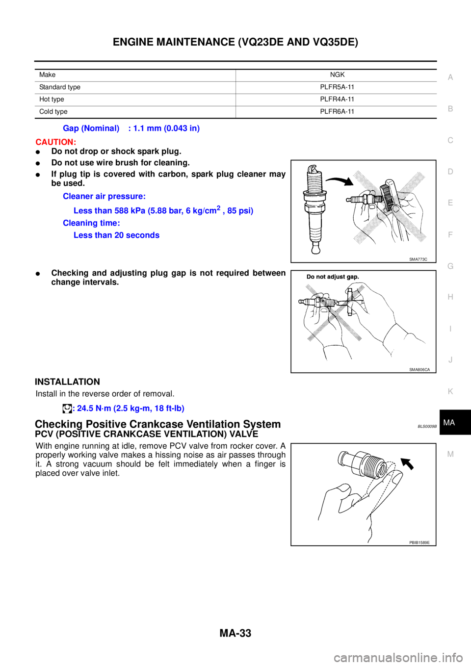
CAUTION:
�Do not drop or shock spark plug.
�Do not use wire brush for cleaning.
�If plug tip is covered with carbon, spark plug cleaner may
be used.
�Checking and adjusting plug gap is not required between
change intervals.
INSTALLATION
Install in the reverse order of removal.
Checking Positive Crankcase Ventilation SystemBLS0009B
PCV (POSITIVE CRANKCASE VENTILATION) VALVE
With engine running at idle, remove PCV valve from rocker cover. A
properly working valve makes a hissing noise as air passes through
it. A strong vacuum should be felt immediately when a finger is
placed over valve inlet.
MakeNGK
Standard typePLFR5A-11
Hot typePLFR4A-11
Cold typePLFR6A-11
Gap (Nominal) : 1.1 mm (0.043 in)
Cleaner air pressure:
Less than 588 kPa (5.88 bar, 6 kg/cm
2 , 85 psi)
Cleaning time:
Less than 20 seconds
SMA773C
SMA806CA
: 24.5 N·m (2.5 kg-m, 18 ft-lb)
PBIB1589E
Page 3030 of 3502
PB-4
PARKING BRAKE CONTROL
INSTALLATION
1. Install in the reverse order of removal. Tighten mounting bolts and nuts to the specified torque. Refer to
PB-3, "
Components" .
CAUTION:
Do not reuse adjusting nut after removing it.
2. Adjust parking brake. Refer to PB-2, "
ADJUSTMENT" .
Page 3125 of 3502
STEERING WHEEL
PS-11
C
D
E
F
H
I
J
K
L
MA
B
PS
Removal and InstallationBGS0003T
REMOVAL
NOTE:
When reconnecting spiral cable, fix cable with a tape so that fixing case and rotating part keep aligned. This
will omit neutral position alignment procedure during spiral cable installation.
1. Set vehicle to the straight-ahead direction.
2. Remove driver air bag module. Refer to SRS-35, "
DRIVER AIR BAG MODULE" .
3. Remove steering wheel lock nut after steering is locked.
4. Remove steering wheel with the steering wheel puller [SST].
INSTALLATION
Installation is the reverse order of removal. For tightening torque, refer to PS-12, "COMPONENTS" .
NOTE:
Check the spiral cable neutral position after replacing or rotating spiral cable. Refer to SRS-38, "
INSTALLA-
TION" .
CAUTION:
Do not twist spiral cable freely on excessively after it becomes tight (doing so may cause the cable to
be turn off).
SGIA0080E
Page 3128 of 3502

PS-14
STEERING COLUMN
INSTALLATION
�Installation is the reverse order of removal. For tightening torque, refer to PS-12, "COMPONENTS" .
�Install steering column assembly with tilt neutral condition to steering column assembly. Start installation
from vehicle front at this time.
�When installing lower shaft to steering gear assembly, follow the procedure listed below.
–Set rack of steering gear in the neutral position.
NOTE:
To get the neutral position of rack, turn pinion assembly and measure the distance of inner socket, and
then measure the intermediate position of the distance.
–Align rear cover cap projection (A) with the marking position (B)
of gear housing assembly.
–Install slit part of lower shaft (C) aligning with the projection (A)
of rear cover cap (1). Make sure that the slit part of lower shaft
(C) is aligned with both the projection (A) of rear cover cap (1)
and the marking position (B) of gear housing assembly.
INSPECTION AFTER INSTALLATION
Make sure that steering wheel operates smoothly by turning several times from full left stop to full right stop.
SGIA1140E
Page 3129 of 3502
STEERING COLUMN
PS-15
C
D
E
F
H
I
J
K
L
MA
B
PS
Disassembly and AssemblyBGS0003V
COMPONENTS
DISASSEMBLY
1. Remove spring from jacket tube assembly and column mounting bracket.
2. Remove the TORX bolt (securing tilt lever), then remove tilt lever and adjusting nut from jacket tube
assembly.
3. Remove column mounting bracket from jacket tube assembly.
INSPECTION AFTER DISASSEMBLY
�Check jacket tube assembly for deformation or damage. Replace if there are.
�Check tilt mechanism components for malfunction. Replace if there are.
ASSEMBLY
�Assembly is the reverse order of the disassembly. For tightening torque, refer to PS-15, "COMPONENTS"
.
�Tighten TORX nut (for securing tilt lever) to the specified torque
so that tilt lever locks when tilt lever turns from unlock to lock.
Refer to PS-15, "
COMPONENTS" .
1. Jacket tube assembly 2. Column mounting bracket 3. Spring
4. Adjusting nut 5. Tilt lever
SGIA0994E
SGIA0992E
Page 3133 of 3502

POWER STEERING GEAR AND LINKAGE
PS-19
C
D
E
F
H
I
J
K
L
MA
B
PS
8. Remove high-pressure tube and low-pressure hose of hydraulic
piping, and then drain power steering fluid. Refer to PS-39,
"HYDRAULIC LINE" .
9. Remove fixing bolt (lower side) of lower shaft.
10. Remove stabilizer connecting rod lower nut, and then separate
stabilizer connecting rod from stabilizer bar. Refer to FSU-7,
"Components" .
11. Remove mounting nut and bolt of transverse link ball joint, and
then remove transverse link from steering knuckle. Refer to
FSU-7, "
Components" .
12. Remove front exhaust tube. Refer to EX-2, "
EXHAUST SYS-
TEM" .
13. Remove steering hydraulic piping bracket from front suspension member and rear engine mounting insu-
lator. Refer to PS-39, "
HYDRAULIC LINE" .
14. Set jack under transaxle assembly.
15. Remove front engine mounting bracket and front engine mounting insulator mounting bolts. Refer to EM-
77, "ENGINE ASSEMBLY" .
16. Remove rear engine mounting bracket and rear engine mounting insulator mounting bolts. Refer to EM-
77, "ENGINE ASSEMBLY" .
17. Remove rear engine mounting insulator and front suspension member fixing nuts and bolts. Refer to EM-
77, "ENGINE ASSEMBLY" .
18. Set jack under front suspension member.
19. Loosen mounting nuts (front side) of front suspension member. Refer to FSU-7, "
Components" .
20. Remove mounting bolts (body side) of member stay, and then loosen nuts (front suspension member side
mounting point) of member stay. Refer to FSU-7, "
Components" .
21. Gradually lower jack to remove steering gear assembly mounting nut and bolts and remove rack mounting
bracket, rack mounting insulator and sleeve from vehicle, and then remove steering gear assembly from
vehicle.
INSTALLATION
Installation is the reverse order of removal. For tightening torque, refer to PS-17, "COMPONENTS" .
�When installing lower shaft to steering gear assembly, follow the procedure listed below.
–Set rack of steering gear in the neutral position.
NOTE:
To get the neutral position of rack, turn pinion assembly and measure the distance of inner socket, and
then measure the intermediate position of the distance.
–Align rear cover cap projection (A) with the marking position (B)
of gear housing assembly.
–Install slit part of lower shaft (C) aligning with the projection (A)
of rear cover cap (1). Make sure that the slit part of lower shaft
(C) is aligned with both the projection (A) of rear cover cap (1)
and the marking position (B) of gear housing assembly.
–After installation, bleed air from the steering hydraulic system.
Refer to PS-39, "
HYDRAULIC LINE" .
–Perform final tightening of nuts and bolts on each part under
unladen conditions with tyres on level ground when removing
steering gear assembly. Check wheel alignment. Refer to FSU-
5, "Wheel Alignment Inspection" .
–Adjust neutral position of steering angle sensor after checking the wheel alignment for the models with
VDC. Refer to BRC-40, "
Adjustment of Steering Angle Sensor Neutral Position" .
INSPECTION AFTER INSTALLATION
Make sure that steering wheel operates smoothly by turning several times from full left stop to full right stop.
SGIA0987E
SGIA1140E
Page 3144 of 3502

PS-30
POWER STEERING OIL PUMP
Removal and InstallationBGS0003Z
REMOVAL
1. Drain power steering fluid from reservoir tank.
2. Remove tyres from vehicle.
3. Remove side splash guard.
4. Remove heat insulator from vehicle. (Except for QR20DE mod-
els).
5. Loosen drive belt. Refer to EM-14, "
DRIVE BELTS" (QR20DE
models), EM-128, "
DRIVE BELTS" (Except for QR20DE mod-
els).
6. Remove drive belt from oil pump pulley.
7. Disconnect the pressure sensor electrical connector.
8. Remove piping of high pressure and low pressure (drain fluid
from their pipings). Refer to PS-39, "
HYDRAULIC LINE" .
9. Remove power steering oil pump mounting bolts, and then
remove power steering oil pump. Refer to PS-39, "
HYDRAULIC
LINE" .
INSTALLATION
�Installation is the reverse order of removal. For tightening torque, refer to PS-39, "HYDRAULIC LINE" .
�Perform the following procedure after installing.
–Adjust belt tension (Except for QR20DE models). Refer to EM-128, "DRIVE BELTS" .
–About the installation of QR20DE drive belt, refer to EM-14, "DRIVE BELTS" .
–Bleed air. Refer to PS-7, "Air Bleeding Hydraulic System" .
SGIA0502E
Page 3162 of 3502

RAX-4
WHEEL HUB
4. Put matching mark on disc rotor and wheel hub and bearing
assembly, then remove disc rotor.
5. Remove bolts, and then remove wheel hub and bearing assem-
bly from axle housing.
6. Remove hub cap from axle housing.
Axle Housing
1. Remove wheel hub and bearing assembly from axle housing. Refer to RAX-3, "Wheel Hub and Bearing
Assembly" .
2. Remove parking brake shoe and parking brake cable from back plate. Refer to PB-5, "
PARKING BRAKE
SHOE" , PB-3, "PARKING BRAKE CONTROL" .
3. Remove anchor block mounting nuts, then remove anchor block and back plate from axle housing.
4. Remove coil spring. Refer to RSU-15, "
REAR LOWER LINK & COIL SPRING" .
5. Remove axle housing side nuts and bolts on radius rod and front lower link. Refer to RSU-13, "
RADIUS
ROD" , RSU-14, "FRONT LOWER LINK" .
6. Remove cotter pin, and then loosen suspension arm mounting nut of axle housing.
7. Remove suspension arm from axle housing so as not to damage ball joint boot using the ball joint remover
(suitable tool), and then remove axle housing from vehicle.
CAUTION:
Temporarily tighten the nut to prevent damage to threads and to prevent ball joint remover (suit-
able tool) from suddenly coming off.
INSPECTION AFTER REMOVAL
Check the components for deformation, cracks and other damage. Replace if there are.
Ball Joint Inspection
Check suspension arm ball joint boot for breakage, axial play, and torque. Refer to RSU-11, "INSPECTION
AFTER REMOVAL" .
INSTALLATION
Wheel Hub and Bearing Assembly
�Installation is the reverse order of the removal. For tightening torque, refer to RAX-3, "COMPONENT" .
NOTE:
Do not reuse non-reusable parts.
�Assemble disc rotor and wheel hub and bearing assembly by
aligning each matching mark as shown in the figure when install-
ing disc rotor.
NOTE:
Refer to BR-33, "
REAR DISC BRAKE" for assembly when
removing disc rotor without matching mark.
�Check wheel sensor harness for proper connection. Refer to
BRC-33, "
WHEEL SENSORS" .
�Adjust neutral position of steering angle sensor after checking
the wheel alignment for the models with VDC. Refer to BRC-40,
"Adjustment of Steering Angle Sensor Neutral Position" .
SDIA2638E
SDIA2638E