Page 3361 of 4500

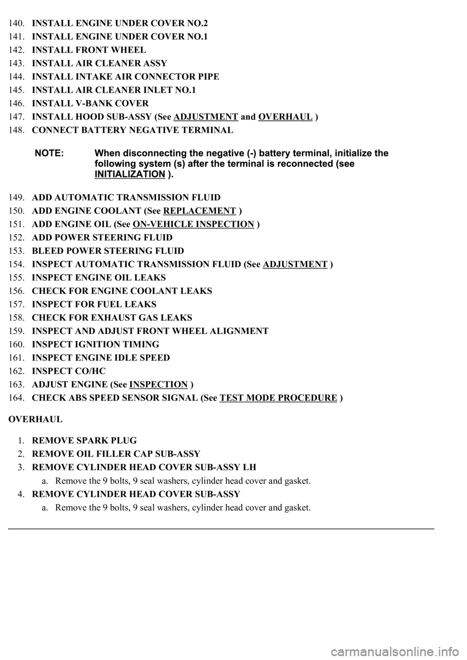
140.INSTALL ENGINE UNDER COVER NO.2
141.INSTALL ENGINE UNDER COVER NO.1
142.INSTALL FRONT WHEEL
143.INSTALL AIR CLEANER ASSY
144.INSTALL INTAKE AIR CONNECTOR PIPE
145.INSTALL AIR CLEANER INLET NO.1
146.INSTALL V-BANK COVER
147.INSTALL HOOD SUB-ASSY (See ADJUSTMENT
and OVERHAUL )
148.CONNECT BATTERY NEGATIVE TERMINAL
149.ADD AUTOMATIC TRANSMISSION FLUID
150.ADD ENGINE COOLANT (See REPLACEMENT
)
151.ADD ENGINE OIL (See ON
-VEHICLE INSPECTION )
152.ADD POWER STEERING FLUID
153.BLEED POWER STEERING FLUID
154.INSPECT AUTOMATIC TRANSMISSION FLUID (See ADJUSTMENT
)
155.INSPECT ENGINE OIL LEAKS
156.CHECK FOR ENGINE COOLANT LEAKS
157.INSPECT FOR FUEL LEAKS
158.CHECK FOR EXHAUST GAS LEAKS
159.INSPECT AND ADJUST FRONT WHEEL ALIGNMENT
160.INSPECT IGNITION TIMING
161.INSPECT ENGINE IDLE SPEED
162.INSPECT CO/HC
163.ADJUST ENGINE (See INSPECTION
)
164.CHECK ABS SPEED SENSOR SIGNAL (See TEST MODE PROCEDURE
)
OVERHAUL
1.REMOVE SPARK PLUG
2.REMOVE OIL FILLER CAP SUB-ASSY
3.REMOVE CYLINDER HEAD COVER SUB-ASSY LH
a. Remove the 9 bolts, 9 seal washers, cylinder head cover and gasket.
4.REMOVE CYLINDER HEAD COVER SUB-ASSY
a. Remove the 9 bolts, 9 seal washers, c
ylinder head cover and gasket.
Page 3881 of 4500
Fig. 92: Identifying Rear Sunshade System Diagram
Courtesy of TOYOTA MOTOR SALES, U.S.A., INC.
ON-VEHICLE INSPECTION
1.BASIC INSPECTION
a. With the ignition switch ON, the shift lever in the P position and the rear sunshade fully open, press
the rear sunshade switch built into the front or rear control switch. Check that the rear sunshade
closes fully.
b. After step (a), press the same switch again and check that the rear sunshade opens fully.
c. With the ignition switch ON, the shift lever in the P position and the rear sunshade fully closed,
move the shift lever into the R (reverse) position. Check that the rear sunshade opens fully.
d. Turn the ignition switch OFF while the rear sunshade is moving up/down. Check that the rear
sunshade stops moving.
e. After step (d), turn the ignition switch ON and press the rear sunshade switch built into the front or
rear control switch. Check that the rear sunshade opens full
y.
Page 3885 of 4500
Fig. 96: Inspecting Rear Sunshade Switch
Courtesy of TOYOTA MOTOR SALES, U.S.A., INC.
If the result is not as specified, replace the switch.
4.INSPECT LUGGAGE ROOM JUNCTION BLOCK ECU
a. Disconnect the relay connector.
b. Measure the voltage of each terminal of the wire harness side connector.
Standard:
LUGGAGE ROOM JUNCTION BLOCK ECU - VOLTAGE TABLE
Tester ConnectionConditionSpecified Condition
1 (IG) - Body groundIgnition switch ON10 to 14 V
1 (IG) - Body groundIgnition switch OFF or ACCBelow 1 V
2 (REV) - Body groundIgnition switch ON, Shift position
R10 to 14 V
2 (REV) - Body groundIgnition switch ON, Shift position Below 1 V
Page 3921 of 4500
1.CHECK DRIVER SEAT ECU
Fig. 7: Identifying Terminals Of Driver Seat ECU
Courtesy of TOYOTA MOTOR SALES, U.S.A., INC.
a. Disconnect the D27 and D28 ECU connectors.
b. Measure the voltage of the wire harness side connectors.
Standard:
DRIVER SEAT ECU TERMINALS REFERENCE
If the result is not as specified, there may be a malfunction on the wire harness side.
c. Reconnect the D27 and D28 ECU connectors.
d. Initialize the front power seat (SEE INITIALIZATION
).
e. Measure the voltage of connectors.
Standard:
Symbols (Terminal
No.)Wiring ColorTerminal
DescriptionConditionSpecified
Condition
GND (D27-6) - Body
groundW-B - Body
groundGroundAlwaysBelow 1 V
SGND (D28-1) - Body
groundBR - Body
groundGroundAlwaysBelow 1 V
IG (D28-10) - SGND
(D28-1)R-L - BRIgnition switchIgnition switch OFF
--> ON0 V --> 10 to 14
V
+B (D27-14) - GND
(D27-6)B-R - W-BBatteryAlways10 to 14V
SYSB (D28-9) - SGND
(D28-1)V-Y - BRBatteryAlways10 to 14V
Page 3923 of 4500

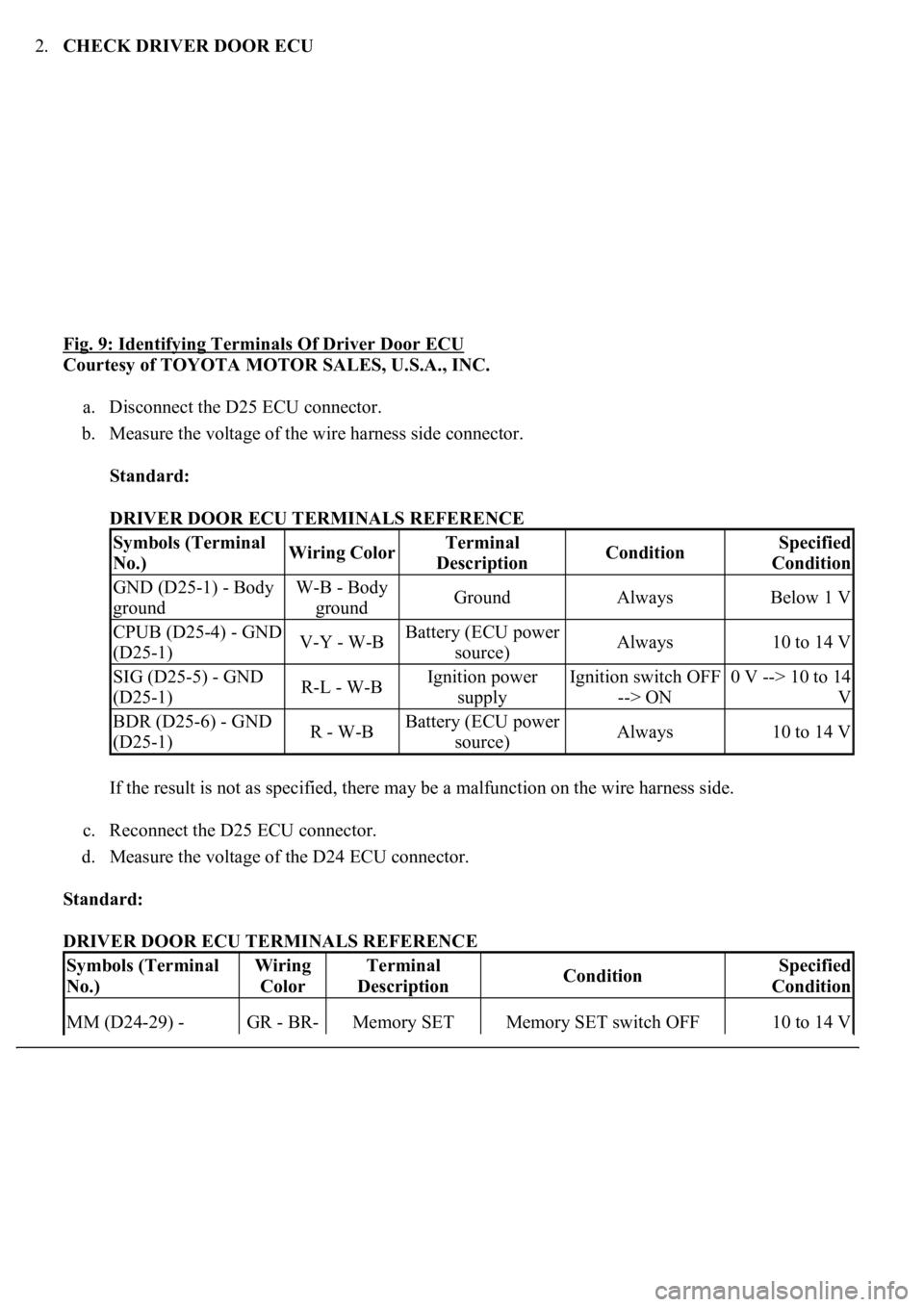
2.CHECK DRIVER DOOR ECU
Fig. 9: Identifying Terminals Of Driver Door ECU
Courtesy of TOYOTA MOTOR SALES, U.S.A., INC.
a. Disconnect the D25 ECU connector.
b. Measure the voltage of the wire harness side connector.
Standard:
DRIVER DOOR ECU TERMINALS REFERENCE
If the result is not as specified, there may be a malfunction on the wire harness side.
c. Reconnect the D25 ECU connector.
d. Measure the voltage of the D24 ECU connector.
Standard:
DRIVER DOOR ECU TERMINALS REFERENCE
Symbols (Terminal
No.)Wiring ColorTerminal
DescriptionConditionSpecified
Condition
GND (D25-1) - Body
groundW-B - Body
groundGroundAlwaysBelow 1 V
CPUB (D25-4) - GND
(D25-1)V-Y - W-BBattery (ECU power
source)Always10 to 14 V
SIG (D25-5) - GND
(D25-1)R-L - W-BIgnition power
supplyIgnition switch OFF
--> ON0 V --> 10 to 14
V
BDR (D25-6) - GND
(D25-1)R - W-BBattery (ECU power
source)Always10 to 14 V
Symbols (Terminal
No.)Wiring
ColorTerminal
DescriptionConditionSpecified
Condition
MM (D24-29) - GR - BR-Memory SET Memory SET switch OFF 10 to 14 V
Page 3925 of 4500

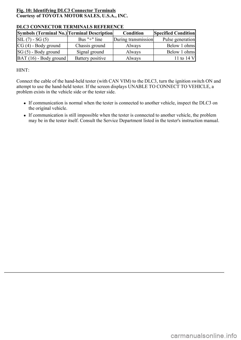
Fig. 10: Identifying DLC3 Connector Terminals
Courtesy of TOYOTA MOTOR SALES, U.S.A., INC.
DLC3 CONNECTOR TERMINALS REFERENCE
HINT:
Connect the cable of the hand-held tester (with CAN VIM) to the DLC3, turn the ignition switch ON and
attempt to use the hand-held tester. If the screen displays UNABLE TO CONNECT TO VEHICLE, a
problem exists in the vehicle side or the tester side.
If communication is normal when the tester is connected to another vehicle, inspect the DLC3 on
the original vehicle.
If communication is still impossible when the tester is connected to another vehicle, the problem
may be in the tester itself. Consult the Service Department listed in the tester's instruction manual.
Symbols (Terminal No.)Terminal DescriptionConditionSpecified Condition
SIL (7) - SG (5)Bus "+" lineDuring transmissionPulse generation
CG (4) - Body groundChassis groundAlwaysBelow 1 ohms
SG (5) - Body groundSignal groundAlwaysBelow 1 ohms
BAT (16) - Body groundBattery positiveAlways11 to 14 V
Page 3926 of 4500
Fig. 11: Connecting Cable Of Hand-Held Tester (With CAN VIM) To DLC3
Courtesy of TOYOTA MOTOR SALES, U.S.A., INC.
3.INSPECT BATTERY VOLTAGE
Standard: 11 to 14 V
If voltage is below 11 V, replace the battery before proceeding.
1.DATA LIST
HINT:
<00380056004c0051004a00030057004b00480003004b0044005100470010004b0048004f00470003005700480056005700480055000a0056000300270024003700240003002f002c0036003700030044004f004f0052005a005600030056005a004c005700
46004b000f0003005600480051005600520055000f00030044[ctuator and other items to be read
without removing any parts. Reading the DATA LIST early in troubleshooting is one way to save time.
a. Connect the hand-held tester (with CAN VIM) to the DLC3.
b. Turn the ignition switch ON.
c. Read the DATA LIST.
Driver seat ECU:
Page 3930 of 4500

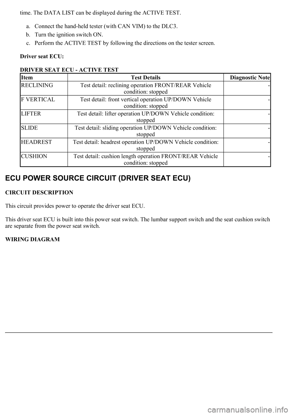
time. The DATA LIST can be displayed during the ACTIVE TEST.
a. Connect the hand-held tester (with CAN VIM) to the DLC3.
b. Turn the ignition switch ON.
c. Perform the ACTIVE TEST by following the directions on the tester screen.
Driver seat ECU:
DRIVER SEAT ECU - ACTIVE TEST
CIRCUIT DESCRIPTION
This circuit provides power to operate the driver seat ECU.
This driver seat ECU is built into this power seat switch. The lumbar support switch and the seat cushion switch
are separate from the power seat switch.
WIRING DIAGRAM
ItemTest DetailsDiagnostic Note
RECLININGTest detail: reclining operation FRONT/REAR Vehicle
condition: stopped-
F VERTICALTest detail: front vertical operation UP/DOWN Vehicle
condition: stopped-
LIFTERTest detail: lifter operation UP/DOWN Vehicle condition:
stopped-
SLIDETest detail: sliding operation UP/DOWN Vehicle condition:
stopped-
HEADRESTTest detail: headrest operation UP/DOWN Vehicle condition:
stopped-
CUSHIONTest detail: cushion length operation FRONT/REAR Vehicle
condition: stopped-