Page 4262 of 4500
a. Using a gas leak detector, check for leakage of refrigerant.
<002c004900030057004b0048005500480003004c0056000300440051005c0003004f00480044004e0044004a0048000f0003005500480053004f00440046004800030057004b00480003004600520050005300550048005600560052005500030044005600
56004800500045004f005c00110003[
4.INSPECT W/PULLEY COMPRESSOR ASSY
a. Check operation of w/pulley compressor assy.
1. Start the engine.
2. Inspect the compressor pulley.
Standard: The compressor shaft rotates along with the pulley
Fig. 75: Inspecting W/Pulley Compressor Assy
Courtesy of TOYOTA MOTOR SALES, U.S.A., INC.
5.INSPECT SOLENOID OF THE EXTERNALLY CHANGEABLE COMPRESSOR
a. Turn the ignition switch off.
b. Disconnect the connector.
c. Measure resistance between terminals 1 and 2.
Standard resistance: 10 to 11 ohms
HINT:
If resistance is not within the specified ran
ge, replace the compressor.
Page 4327 of 4500
LOCATION
Fig. 1: Identifying Ignition System Components And Replacement Location
Courtesy of TOYOTA MOTOR SALES, U.S.A., INC.
SYSTEM DIAGRAM
The ECM determines ignition timing based on signals from various sensors.
Page 4328 of 4500
Fig. 2: Ignition System Diagram (1 Of 2)
Courtesy of TOYOTA MOTOR SALES, U.S.A., INC.
Page 4329 of 4500
Fig. 3: Ignition System Diagram (2 Of 2)
Courtesy of TOYOTA MOTOR SALES, U.S.A., INC.
ON-VEHICLE INSPECTION
1.INSPECT IGNITION COIL ASSY (WITH IGNITER) AND PERFORM SPARK TEST
a. Check for DTCs.
b. Check if sparks occur.
1. Remove the ignition coil (see REPLACEMENT
).
2. Remove the spark plug.
3. Install the spark plug to the ignition coil, and connect the ignition coil connector.
4. Disconnect the 8 injector connectors.
5. Ground the spark plu
g.
Page 4330 of 4500
6. Visually check if spark occurs while the engine is being cranked.
If a spark does not occur, perform the test as follows:
Fig. 4: Spark Test Flow Diagram
Courtesy of TOYOTA MOTOR SALES, U.S.A., INC.
7. Using a 16 mm (0.63 in.) plug wrench, install the spark plugs.
Torque: 18 N.m (180 kgf.cm, 13 ft.lbf)
8. Install the ignition coils (see REPLACEMENT
).
Page 4338 of 4500
Fig. 11: Identifying Ignition Coil Components And Replacements
Courtesy of TOYOTA MOTOR SALES, U.S.A., INC.
REPLACEMENT
1.REMOVE V-BANK COVER
2.REMOVE ENGINE ROOM SIDE COVER
3.REMOVE INTAKE AIR CONNECTOR PIPE
Page 4339 of 4500
4.REMOVE OIL LEVEL GAGE SUB-ASSY (See step 8 in REPLACEMENT )
5.REMOVE IGNITION COIL ASSY
a. Disconnect the ignition coil connector.
b. Remove the bolt and pull out the ignition coil.
Fig. 12: Removing Ignition Coil Assy
Courtesy of TOYOTA MOTOR SALES, U.S.A., INC.
6.INSTALL IGNITION COIL ASSY
a. Connect a new ignition coil to the spark plug, attach the ignition coil to the cylinder head cover,
and install the bolt.
Torque: 7.5 N.m (76 kgf.cm, 66 in.lbf)
b. Connect the ignition coil connector.
7.INSTALL OIL LEVEL GAGE SUB-ASSY (See step 27 in REPLACEMENT
)
8.INSTALL INTAKE AIR CONNECTOR PIPE
9.INSTALL V-BANK COVER
10.INSTALL ENGINE ROOM SIDE COVER
Page 4417 of 4500

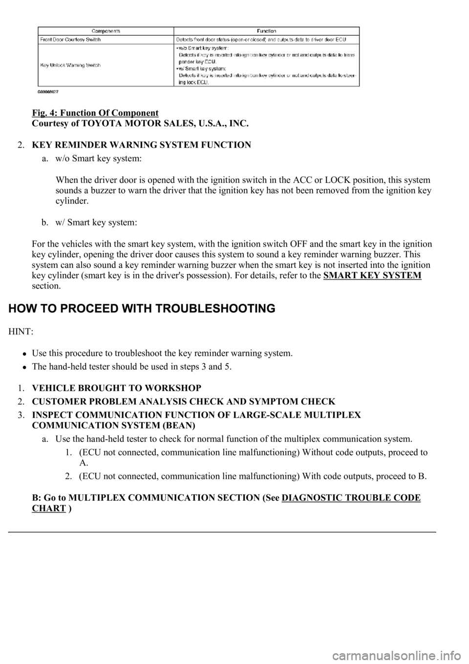
Fig. 4: Function Of Component
Courtesy of TOYOTA MOTOR SALES, U.S.A., INC.
2.KEY REMINDER WARNING SYSTEM FUNCTION
a. w/o Smart key system:
When the driver door is opened with the ignition switch in the ACC or LOCK position, this system
sounds a buzzer to warn the driver that the ignition key has not been removed from the ignition key
cylinder.
b. w/ Smart key system:
For the vehicles with the smart key system, with the ignition switch OFF and the smart key in the ignition
key cylinder, opening the driver door causes this system to sound a key reminder warning buzzer. This
system can also sound a key reminder warning buzzer when the smart key is not inserted into the ignition
key cylinder (smart key is in the driver's possession). For details, refer to the SMART KEY SYSTEM
section.
HINT:
Use this procedure to troubleshoot the key reminder warning system.
<0037004b00480003004b0044005100470010004b0048004f0047000300570048005600570048005500030056004b00520058004f0047000300450048000300580056004800470003004c005100030056005700480053005600030016000300440051004700
030018001100030003[
1.VEHICLE BROUGHT TO WORKSHOP
2.CUSTOMER PROBLEM ANALYSIS CHECK AND SYMPTOM CHECK
3.INSPECT COMMUNICATION FUNCTION OF LARGE-SCALE MULTIPLEX
COMMUNICATION SYSTEM (BEAN)
a. Use the hand-held tester to check for normal function of the multiplex communication system.
1. (ECU not connected, communication line malfunctioning) Without code outputs, proceed to
A.
2. (ECU not connected, communication line malfunctioning) With code outputs, proceed to B.
B: Go to MULTIPLEX COMMUNICATION SECTION (See DIAGNOSTIC TROUBLE CODE
CHART )