Page 3934 of 4500
Courtesy of TOYOTA MOTOR SALES, U.S.A., INC.
Standard:
TESTER CONNECTION AND SPECIFIED CONDITION
NG: REPAIR OR REPLACE HARNESS AND CONNECTOR
OK: PROCEED TO NEXT CIRCUIT INSPECTION SHOWN ON PROBLEM SYMPTOMS
TABLE
CIRCUIT DESCRIPTION
This circuit supplies power to operate the driver side J/B ECU.
WIRING DIAGRAM
Tester ConnectionSwitch ConditionSpecified Condition
D27-14 (+B) - Body groundAlways10 to 14 V
D28-9 (SYSB) - Body groundAlways10 to 14 V
D28-10 (IG) - Body groundIgnition switch OFF --> ON0 V --> 10 to 14 V
D27-6 (GND) - Body groundAlwaysBelow 1 ohms
D28-1 (SGND) - Body groundAlwaysBelow 1 ohms
Page 3937 of 4500
a. Disconnect the D25 ECU connector.
b. Measure the voltage and resistance of the wire harness side connector.
Standard:
TESTER CONNECTION AND SPECIFIED CONDITION
Fig. 20: Identifying D25 Driver Door ECU Connector Terminals
Courtesy of TOYOTA MOTOR SALES, U.S.A., INC.
NG: REPAIR OR REPLACE HARNESS AND CONNECTOR
OK: PROCEED TO NEXT CIRCUIT INSPECTION SHOWN ON PROBLEM SYMPTOMS
TABLE
Tester connectionConditionSpecified condition
D25-4 (CPUB) - Body groundAlways10 to 14 V
D25-6 (BDR) - Body groundAlways10 to 14 V
D25-5 (SIG) - Body groundIgnition switch OFF --> ON0 V --> 10 to 14 V
D25-1 (GND) - Body groundAlwaysBelow 1 ohms
Page 3939 of 4500

INSPECTION PROCEDURE
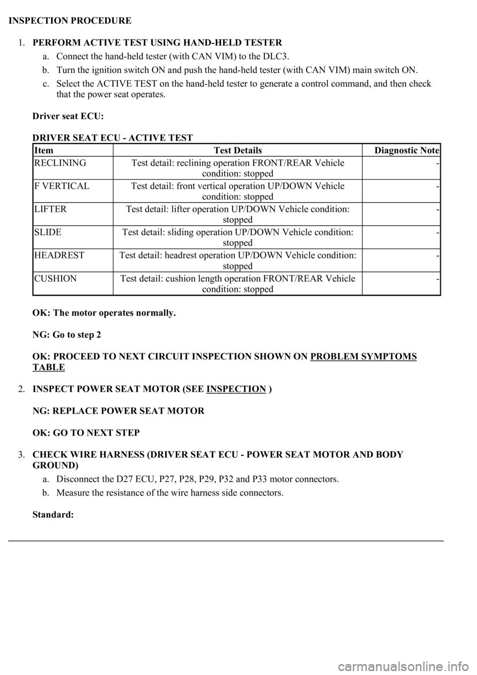
1.PERFORM ACTIVE TEST USING HAND-HELD TESTER
a. Connect the hand-held tester (with CAN VIM) to the DLC3.
b. Turn the ignition switch ON and push the hand-held tester (with CAN VIM) main switch ON.
c. Select the ACTIVE TEST on the hand-held tester to generate a control command, and then check
that the power seat operates.
Driver seat ECU:
DRIVER SEAT ECU - ACTIVE TEST
OK: The motor operates normally.
NG: Go to step 2
OK: PROCEED TO NEXT CIRCUIT INSPECTION SHOWN ON PROBLEM SYMPTOMS
TABLE
2.INSPECT POWER SEAT MOTOR (SEE INSPECTION
)
NG: REPLACE POWER SEAT MOTOR
OK: GO TO NEXT STEP
3.CHECK WIRE HARNESS (DRIVER SEAT ECU - POWER SEAT MOTOR AND BODY
GROUND)
a. Disconnect the D27 ECU, P27, P28, P29, P32 and P33 motor connectors.
b. Measure the resistance of the wire harness side connectors.
Standard:
ItemTest DetailsDiagnostic Note
RECLININGTest detail: reclining operation FRONT/REAR Vehicle
condition: stopped-
F VERTICALTest detail: front vertical operation UP/DOWN Vehicle
condition: stopped-
LIFTERTest detail: lifter operation UP/DOWN Vehicle condition:
stopped-
SLIDETest detail: sliding operation UP/DOWN Vehicle condition:
stopped-
HEADRESTTest detail: headrest operation UP/DOWN Vehicle condition:
stopped-
CUSHIONTest detail: cushion length operation FRONT/REAR Vehicle
condition: stopped-
Page 3944 of 4500

INSPECTION PROCEDURE
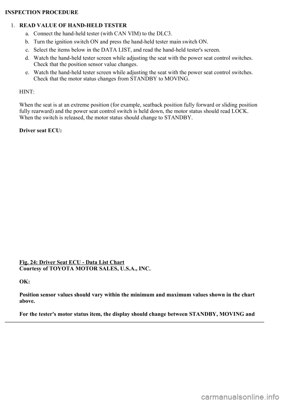
1.READ VALUE OF HAND-HELD TESTER
a. Connect the hand-held tester (with CAN VIM) to the DLC3.
b. Turn the ignition switch ON and press the hand-held tester main switch ON.
c. Select the items below in the DATA LIST, and read the hand-held tester's screen.
d. Watch the hand-held tester screen while adjusting the seat with the power seat control switches.
Check that the position sensor value changes.
e. Watch the hand-held tester screen while adjusting the seat with the power seat control switches.
Check that the motor status changes from STANDBY to MOVING.
HINT:
When the seat is at an extreme position (for example, seatback position fully forward or sliding position
fully rearward) and the power seat control switch is held down, the motor status should read LOCK.
When the switch is released, the motor status should change to STANDBY.
Driver seat ECU:
Fig. 24: Driver Seat ECU
- Data List Chart
Courtesy of TOYOTA MOTOR SALES, U.S.A., INC.
OK:
Position sensor values should vary within the minimum and maximum values shown in the chart
above.
For the tester's motor status item, the display should change between STANDBY, MOVING and
Page 3947 of 4500
OK: GO TO NEXT STEP
3.CHECK DRIVER SEAT ECU (SENSOR POWER SOURCE VOLTAGE)
a. Turn the ignition switch ON.
b. Measure the voltage of the ECU connector.
Standard:
TESTER CONNECTION AND SPECIFIED CONDITION
Fig. 26: Identifying D28 Driver Seat ECU Connector Terminals
Courtesy of TOYOTA MOTOR SALES, U.S.A., INC.
NG: REPLACE DRIVER SEAT ECU
OK: GO TO NEXT STEP
Tester connectionSpecified condition
D28-16 (PVCC) - Body ground8V
Page 3948 of 4500
4.CHECK POWER SEAT POSITION SENSOR
a. Turn the ignition switch ON.
b. Measure the voltage of the ECU connector.
Standard:
TESTER CONNECTION AND SPECIFIED CONDITION
HINT:
Check the power seat position sensors that are malfunctioning.
Run the motors and check that the voltage readings vary within the "specified condition" shown in the
chart above.
*: If the result is not as specified proceed to steps indicated in this column.
Tester ConnectionSpecified ConditionWhen NG, proceed to*
D28-7 (SSRH) - D28-1 (GND)Varies between 0 to 8 VA
D28-13 (SSRR) - D28-1 (GND)Varies between 0 to 8 VB
D28-6 (SSRV) - D28-1 (GND)Varies between 0 to 8 VB
D28-5 (SSRS) - D28-1 (GND)Varies between 0 to 8 VB
D28-15 (SSRC) - D28-1 (GND)Varies between 0 to 8 VB
D28-14 (SSFV) - D28-1 (GND)Varies between 0 to 8 VB
Page 3960 of 4500
OK:
PROCEED TO NEXT CIRCUIT INSPECTION SHOWN ON PROBLEM SYMPTOMS TABLE
CIRCUIT DESCRIPTION
The driver door ECU detects the condition of the driving memory switch, and sends the information to the
power seat ECU and the tilt and telescopic ECU via the multiplex communication circuit.
WIRING DIAGRAM
Fig. 34: Driving Position Memory Switch (W/ Memory) Wiring Diagram
Courtesy of TOYOTA MOTOR SALES, U.S.A., INC.
INSPECTION PROCEDURE
1.READ VALUE OF HAND-HELD TESTER
a. Connect the hand-held tester (with CAN VIM) to the DLC3.
b. Turn the ignition switch ON and press the hand-held tester main switch ON.
c. Select the items below in the DATA LIST, and read the displa
ys on the hand-held tester.
Page 3970 of 4500

3. After the current has stopped, release the lumbar support switch and wait for approximately
60 seconds.
4. Operate the lumbar support switch and move the seat to the opposite extreme of direction in
step (1). Check that the motor operates.
7.CHECK MEMORY AND REACTIVATION FUNCTION
a. Turn the ignition switch ON and move the shift lever into the P position.
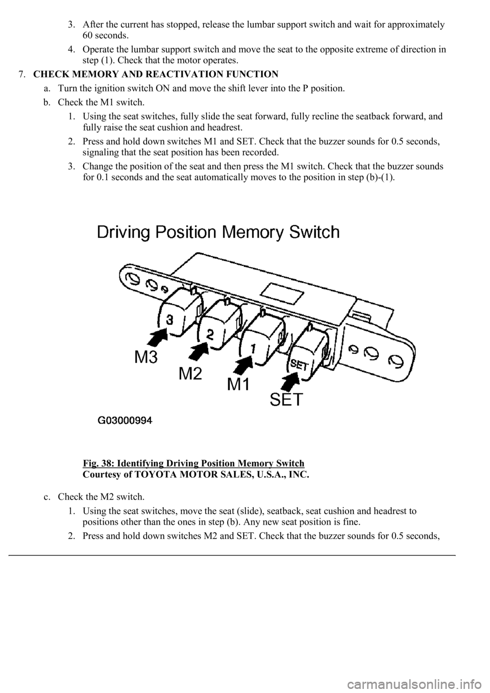
b. Check the M1 switch.
1. Using the seat switches, fully slide the seat forward, fully recline the seatback forward, and
fully raise the seat cushion and headrest.
2. Press and hold down switches M1 and SET. Check that the buzzer sounds for 0.5 seconds,
signaling that the seat position has been recorded.
3. Change the position of the seat and then press the M1 switch. Check that the buzzer sounds
for 0.1 seconds and the seat automatically moves to the position in step (b)-(1).
<0029004c004a001100030016001b001d0003002c0047004800510057004c0049005c004c0051004a000300270055004c0059004c0051004a0003003300520056004c0057004c00520051000300300048005000520055005c00030036005a004c0057004600
4b[
Courtesy of TOYOTA MOTOR SALES, U.S.A., INC.
c. Check the M2 switch.
1. Using the seat switches, move the seat (slide), seatback, seat cushion and headrest to
positions other than the ones in step (b). Any new seat position is fine.
2. Press and hold down switches M2 and SET. Check that the buzzer sounds for 0.5 seconds,