Page 3248 of 4500
Fig. 19: Identifying Waveform 1 Graph
Courtesy of TOYOTA MOTOR SALES, U.S.A., INC.
WAVEFORM 1 REFERENCE TABLE
Waveform 2 (Reference):
TerminalIMI - GND
Tool Setting10 V/DIV., 500 ms/DIV.
ConditionNo key in ignition key cylinder --> Key inserted
Page 3249 of 4500
Fig. 20: Identifying Waveform 2 Graph
Courtesy of TOYOTA MOTOR SALES, U.S.A., INC.
WAVEFORM 2 REFERENCE TABLE
1.DESCRIPTION
a. The ECM controls the vehicle's immobilizer system functions. Immobilizer system data and the
Diagnostic Trouble Codes (DTCs) can be read through the vehicle's Data Link Connector 3
(DLC3). In some cases, a malfunction may be occurring in the immobilizer system even though the
security indicator lamp is not illuminated. When the system seems to be malfunctioning, use the
hand-held tester to check for malfunctions and perform repairs.
2.CHECK DLC3
HINT:
TerminalIMO - GND
Tool Setting10 V/DIV., 500 ms/DIV.
ConditionNo key in ignition key cylinder --> Key inserted
Page 3250 of 4500
The vehicle uses the ISO 15765-4 communication protocol. The terminal arrangement of the DLC3
complies with SAE J1962 and matches the ISO 15765-4 format.
Fig. 21: Identifying DLC3 Connector Terminals
Courtesy of TOYOTA MOTOR SALES, U.S.A., INC.
DLC3 - REFERENCE TABLE
If the result is not as specified, the DLC3 may have a malfunction. Repair or replace the harness and
connector.
HINT:
Connect the cable of the han
d-held tester (with CAN VIM) to the DLC3, turn the ignition switch ON and
Symbols (Terminals No.)Terminal DescriptionConditionSpecified condition
SIL (7) - SG (5)Bus "+" lineDuring transmissionPulse generation
CG (4) - Body groundChassis groundAlwaysBelow 1 ohms
SG (5) - Body groundSignal groundAlwaysBelow 1 ohms
BAT (16) - Body groundBattery positiveAlways11 to 14V
Page 3259 of 4500
Fig. 31: Identifying U7 Switch Connector Terminals
Courtesy of TOYOTA MOTOR SALES, U.S.A., INC.
Standard:
UNLOCK WARNING SWITCH - BODY GROUND - RESISTANCE TABLE
NG: REPAIR OR REPLACE HARNESS AND CONNECTOR
OK: Go to next step
Tester connectionSpecified condition
U7-1 - Body groundBelow 1 ohms
Page 3262 of 4500

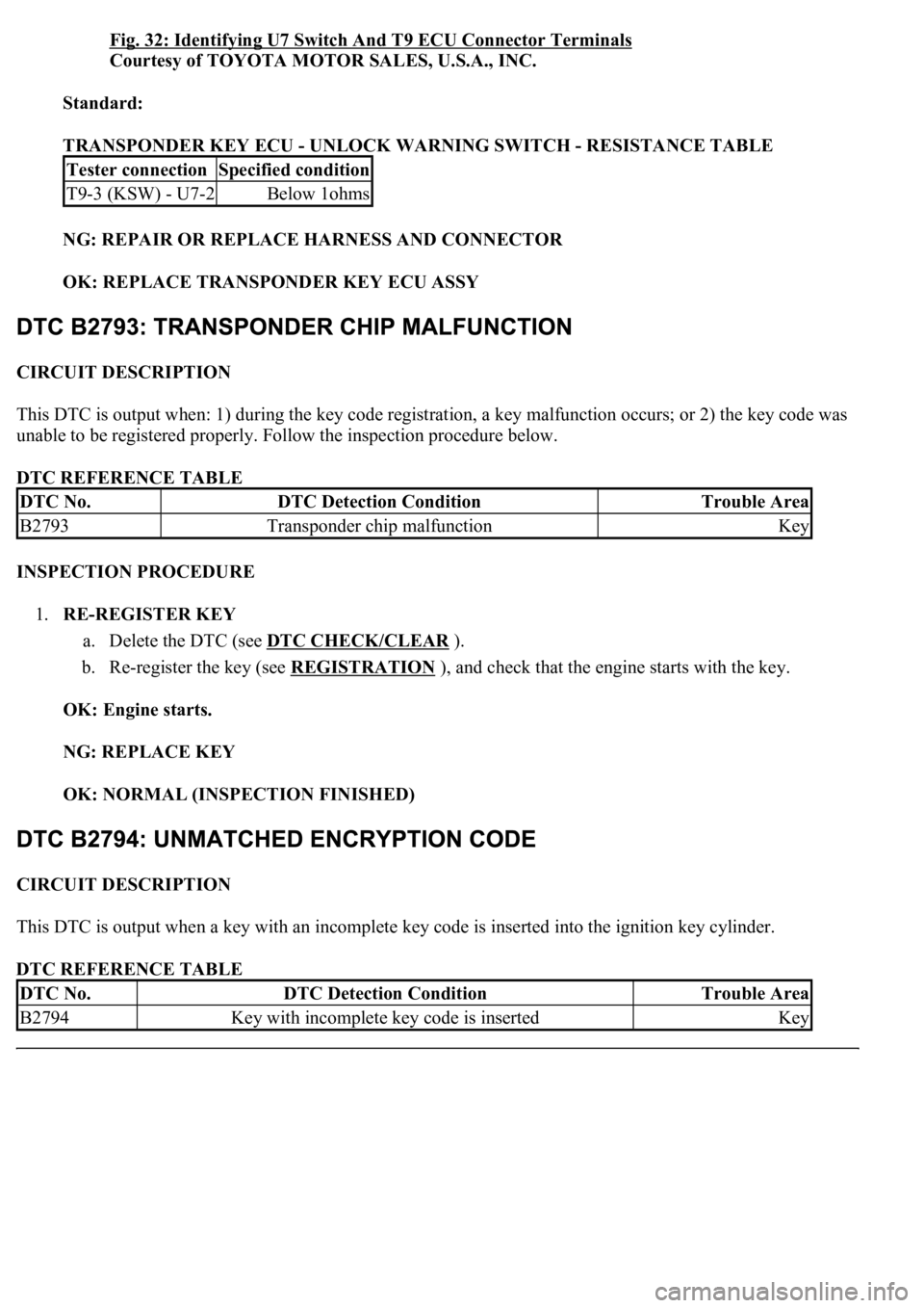
Fig. 32: Identifying U7 Switch And T9 ECU Connector Terminals
Courtesy of TOYOTA MOTOR SALES, U.S.A., INC.
Standard:
TRANSPONDER KEY ECU - UNLOCK WARNING SWITCH - RESISTANCE TABLE
NG: REPAIR OR REPLACE HARNESS AND CONNECTOR
OK: REPLACE TRANSPONDER KEY ECU ASSY
CIRCUIT DESCRIPTION
This DTC is output when: 1) during the key code registration, a key malfunction occurs; or 2) the key code was
unable to be registered properly. Follow the inspection procedure below.
DTC REFERENCE TABLE
INSPECTION PROCEDURE
1.RE-REGISTER KEY
a. Delete the DTC (see DTC CHECK/CLEAR
).
b. Re-register the key (see REGISTRATION
), and check that the engine starts with the key.
OK: Engine starts.
NG: REPLACE KEY
OK: NORMAL (INSPECTION FINISHED)
CIRCUIT DESCRIPTION
This DTC is output when a key with an incomplete key code is inserted into the ignition key cylinder.
DTC REFERENCE TABLE
Tester connectionSpecified condition
T9-3 (KSW) - U7-2Below 1ohms
DTC No.DTC Detection ConditionTrouble Area
B2793Transponder chip malfunctionKey
DTC No.DTC Detection ConditionTrouble Area
B2794Key with incomplete key code is insertedKey
Page 3267 of 4500

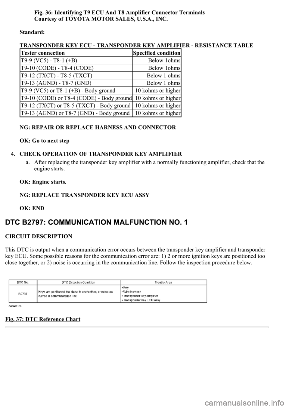
Fig. 36: Identifying T9 ECU And T8 Amplifier Connector Terminals
Courtesy of TOYOTA MOTOR SALES, U.S.A., INC.
Standard:
TRANSPONDER KEY ECU - TRANSPONDER KEY AMPLIFIER - RESISTANCE TABLE
NG: REPAIR OR REPLACE HARNESS AND CONNECTOR
OK: Go to next step
4.CHECK OPERATION OF TRANSPONDER KEY AMPLIFIER
a. After replacing the transponder key amplifier with a normally functioning amplifier, check that the
engine starts.
OK: Engine starts.
NG: REPLACE TRANSPONDER KEY ECU ASSY
OK: END
CIRCUIT DESCRIPTION
This DTC is output when a communication error occurs between the transponder key amplifier and transponder
key ECU. Some possible reasons for the communication error are: 1) 2 or more ignition keys are positioned too
close together, or 2) noise is occurring in the communication line. Follow the inspection procedure below.
Fig. 37: DTC Reference Chart
Tester connectionSpecified condition
T9-9 (VC5) - T8-1 (+B)Below 1ohms
T9-10 (CODE) - T8-4 (CODE)Below 1ohms
T9-12 (TXCT) - T8-5 (TXCT)Below 1 ohms
T9-13 (AGND) - T8-7 (GND)Below 1 ohms
T9-9 (VC5) or T8-1 (+B) - Body ground10 kohms or higher
T9-10 (CODE) or T8-4 (CODE) - Body ground10 kohms or higher
T9-12 (TXCT) or T8-5 (TXCT) - Body ground10 kohms or higher
T9-13 (AGND) or T8-7 (GND) - Body ground10 kohms or higher
Page 3270 of 4500
2.CHECK FOR DTCS
a. Separate the keys from each other. Or, remove the key ring.
b. Delete the DTC (see DTC CHECK/CLEAR
).
c. Insert a key into the ignition cylinder. Remove it. Repeat for all the other keys.
d. Check that no code is output.
NG: Go to step 3
OK: END
3.CHECK TRANSPONDER KEY ECU ASSY
a. Using an oscilloscope or the hand-held tester, check the waveform between the terminals of the T8
amplifier connector and T9 ECU connector. The waveform should be similar to the illustration .
OK: No noise present (see illustration ).
Fig. 40: Identifying Waveform
Courtesy of TOYOTA MOTOR SALES, U.S.A., INC.
WAVEFORM REFERENCE TABLE
TOOL SETTING REFERENCE TABLE
Tester connectionSpecified condition
T9-10 (CODE) - T8-4 (CODE)No noise is present
Page 3273 of 4500

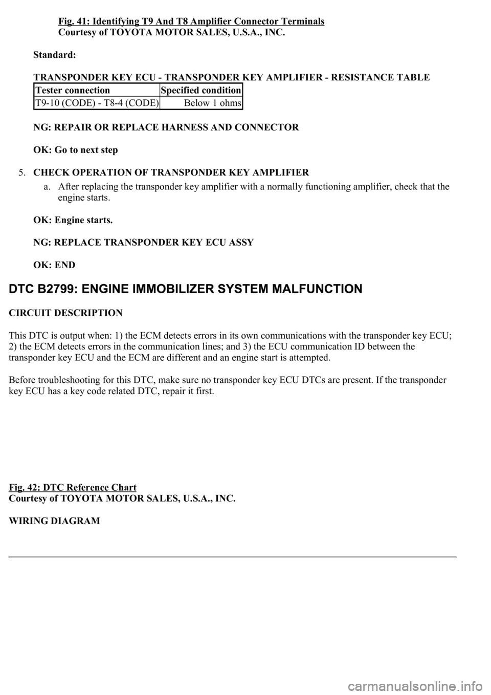
Fig. 41: Identifying T9 And T8 Amplifier Connector Terminals
Courtesy of TOYOTA MOTOR SALES, U.S.A., INC.
Standard:
TRANSPONDER KEY ECU - TRANSPONDER KEY AMPLIFIER - RESISTANCE TABLE
NG: REPAIR OR REPLACE HARNESS AND CONNECTOR
OK: Go to next step
5.CHECK OPERATION OF TRANSPONDER KEY AMPLIFIER
a. After replacing the transponder key amplifier with a normally functioning amplifier, check that the
engine starts.
OK: Engine starts.
NG: REPLACE TRANSPONDER KEY ECU ASSY
OK: END
CIRCUIT DESCRIPTION
This DTC is output when: 1) the ECM detects errors in its own communications with the transponder key ECU;
2) the ECM detects errors in the communication lines; and 3) the ECU communication ID between the
transponder key ECU and the ECM are different and an engine start is attempted.
Before troubleshooting for this DTC, make sure no transponder key ECU DTCs are present. If the transponder
key ECU has a key code related DTC, repair it first.
Fig. 42: DTC Reference Chart
Courtesy of TOYOTA MOTOR SALES, U.S.A., INC.
WIRING DIAGRAM
Tester connectionSpecified condition
T9-10 (CODE) - T8-4 (CODE)Below 1 ohms