Page 4162 of 4500
Fig. 2: Identifying Engine Room No. 1 Junction & Relay Block Components
Courtesy of TOYOTA MOTOR SALES, U.S.A., INC.
Engine Room No. 1 Junction & Relay Block Fuses
FuseSystem
7.5AA/C IGAutomatic Air Conditioning (Front)
7.5AEFI NO.2Engine Control
7.5AFR IGABS
Automatic Air Conditioning (Front)
Back-Up Light
Charging
Clock (w/ LEXUS Navigation System)
Cruise Control
Door Closer (w/ Smart Key System)
Door Closer (w/o Smart Key System)
Door Lock Control (w/ Smart Key System)
Door Lock Control (w/o Smart Key System)
Page 4166 of 4500

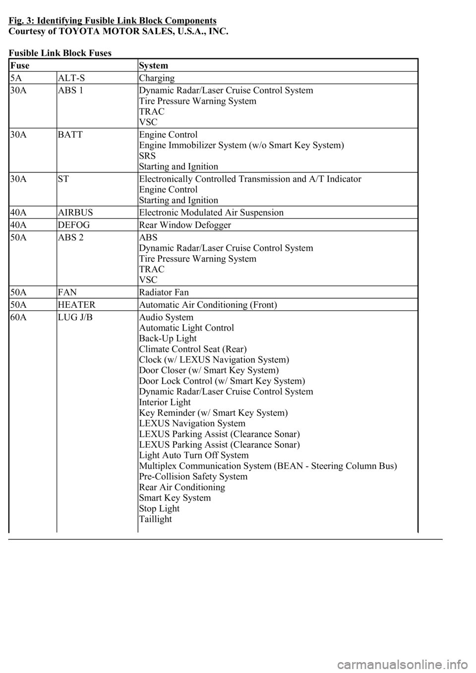
Fig. 3: Identifying Fusible Link Block Components
Courtesy of TOYOTA MOTOR SALES, U.S.A., INC.
Fusible Link Block Fuses
FuseSystem
5AALT-SCharging
30AABS 1Dynamic Radar/Laser Cruise Control System
Tire Pressure Warning System
TRAC
VSC
30ABATTEngine Control
Engine Immobilizer System (w/o Smart Key System)
SRS
Starting and Ignition
30ASTElectronically Controlled Transmission and A/T Indicator
Engine Control
Starting and Ignition
40AAIRBUSElectronic Modulated Air Suspension
40ADEFOGRear Window Defogger
50AABS 2ABS
Dynamic Radar/Laser Cruise Control System
Tire Pressure Warning System
TRAC
VSC
50AFANRadiator Fan
50AHEATERAutomatic Air Conditioning (Front)
60ALUG J/BAudio System
Automatic Light Control
Back-Up Light
Climate Control Seat (Rear)
Clock (w/ LEXUS Navigation System)
Door Closer (w/ Smart Key System)
Door Lock Control (w/ Smart Key System)
Dynamic Radar/Laser Cruise Control System
Interior Light
Key Reminder (w/ Smart Key System)
LEXUS Navigation System
LEXUS Parking Assist (Clearance Sonar)
LEXUS Parking Assist (Clearance Sonar)
Light Auto Turn Off System
Multiplex Communication System (BEAN - Steering Column Bus)
Pre-Collision Safety System
Rear Air Conditioning
Smart Key System
Stop Light
Taillight
Page 4197 of 4500
Fig. 4: Identifying Air Conditioning System Components And Replacements Location (1 Of 2)
Courtesy of TOYOTA MOTOR SALES, U.S.A., INC.
Page 4198 of 4500
Fig. 5: Identifying Air Conditioning System Components And Replacements Location (2 Of 2)
Courtesy of TOYOTA MOTOR SALES, U.S.A., INC.
Page 4216 of 4500
Fig. 31: Identifying Air Conditioning Panel Sub-Assy Components And Replacements
Courtesy of TOYOTA MOTOR SALES, U.S.A., INC.
REPLACEMENT
HINT:
Installation is in the reverse order of removal.
See COMPONENTS .
1.RESTORE SHIP MODE SETTING (W/ CD CHANGER) (See PRECAUTION
)
2.REMOVE INSTRUMENT PANEL FINISH PANEL LOWER CENTER (See step 26 in
REPLACEMENT
)
3.REMOVE PANEL INSTRUMENT CLUSTER FINISH LOWER (See step 27 in
REPLACEMENT
)
4.REMOVE RADIO RECEIVER ASSEMBLY W/BRACKET (See step 4 in REPLACEMENT
)
5.CONFIRM SHIP MODE (W/ CD CHANGER) (See PRECAUTION
)
6.REMOVE TEMPERATURE CONTROL SWITCH ASSY
a. Using a screwdriver, release the 2 claws and remove the temperature control switch.
HINT:
Tape the screwdriver tip before use.
b. Employ the same manner described above to the other side.
c. Disconnect the connectors.
Page 4225 of 4500
Fig. 40: Identifying Air Conditioning Radiator Assy Components And Replacements (1 Of 2)
Courtesy of TOYOTA MOTOR SALES, U.S.A., INC.
Page 4226 of 4500
Fig. 41: Identifying Air Conditioning Radiator Assy Components And Replacements (2 Of 2)
Courtesy of TOYOTA MOTOR SALES, U.S.A., INC.
Page 4293 of 4500
Fig. 104: Identifying Rear Air Conditioning Unit Assy Components And Replacements (1 Of 2)
Courtesy of TOYOTA MOTOR SALES, U.S.A., INC.