Page 4294 of 4500
Fig. 105: Identifying Rear Air Conditioning Unit Assy Components And Replacements (2 Of 2)
Courtesy of TOYOTA MOTOR SALES, U.S.A., INC.
Page 4421 of 4500
Fig. 7: >Identifying Terminals Of T9 ECU
Courtesy of TOYOTA MOTOR SALES, U.S.A., INC.
a. Disconnect the T9 ECU connector.
b. Measure the voltage and resistance of the wire harness side connector.
Standard:
SPECIFIED CONDITION
Symbols (Terminal
No.)
Wiring Color
Terminal
Description
Condition
Specified
Condition
CPUB (T9-1) - GND
(T9-14)V-Y - W-B+B (CPUB) power
supplyAlways10 to 14V
GND (T9-14) - Body
groundW-B - Body
groundGroundAlwaysBelow 1 ohms
Page 4423 of 4500
Fig. 8: Identifying Terminals Of Steering Lock ECU
Courtesy of TOYOTA MOTOR SALES, U.S.A., INC.
a. Disconnect the S46 ECU connector.
b. Measure the voltage and resistance of the wire harness side connector.
Standard:
SPECIFIED CONDITION
Symbols
(Terminal No.)Wiring
ColorTerminal
DescriptionConditionSpecified Condition
CPUB (S46-1) -
Body groundV-Y - Body
ground+B (CPUB)
Power supplyAlways10 to 14V
+B (S46-10)-
Body groundR-L - Body
ground+B Power supplyAlways10 to 14V
LG-B -1: No key in starter
Page 4424 of 4500

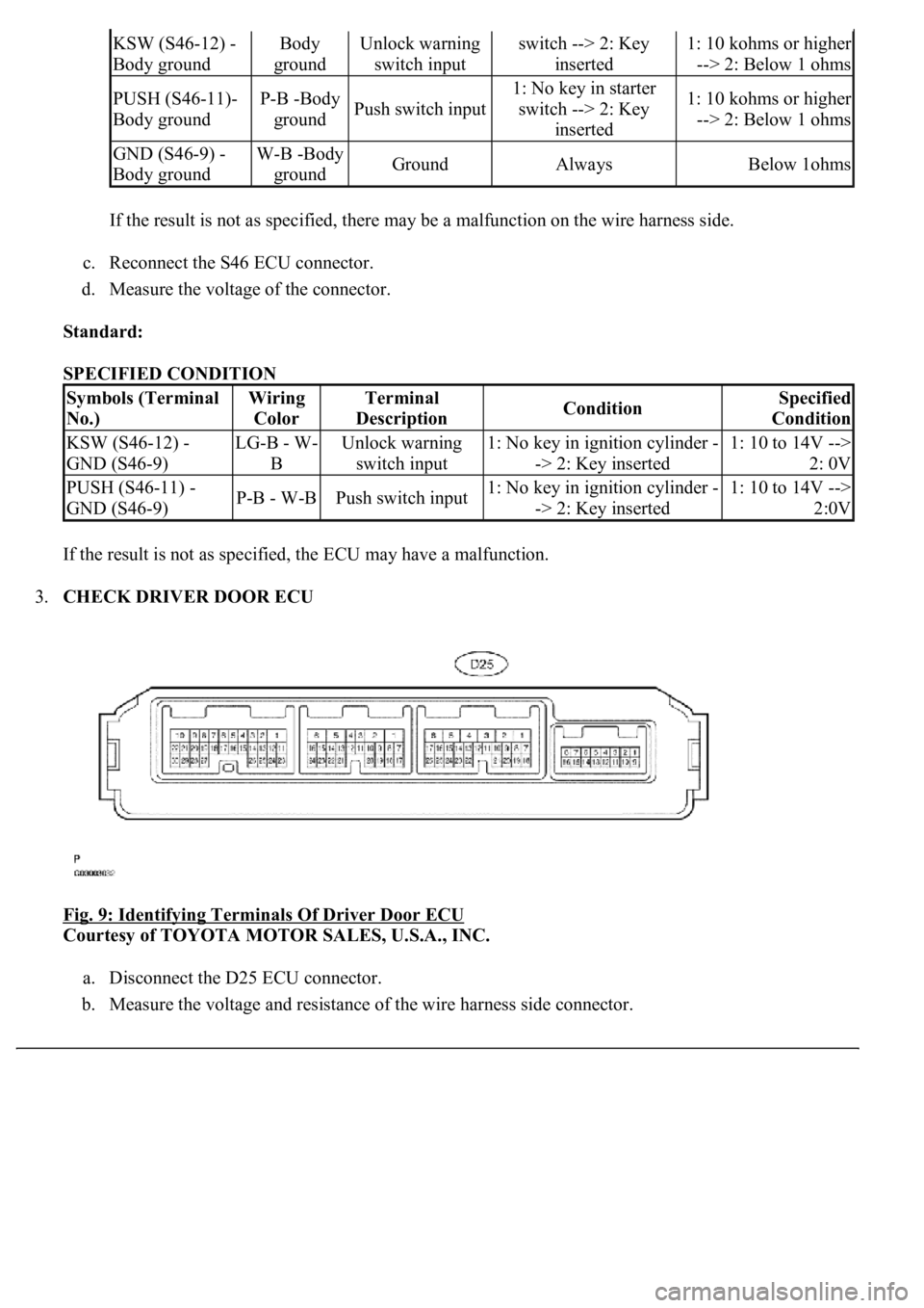
If the result is not as specified, there may be a malfunction on the wire harness side.
c. Reconnect the S46 ECU connector.
d. Measure the voltage of the connector.
Standard:
SPECIFIED CONDITION
If the result is not as specified, the ECU may have a malfunction.
3.CHECK DRIVER DOOR ECU
Fig. 9: Identifying Terminals Of Driver Door ECU
Courtesy of TOYOTA MOTOR SALES, U.S.A., INC.
a. Disconnect the D25 ECU connector.
b. Measure the voltage and resistance of the wire harness side connector.
KSW (S46-12) -
Body groundBody
groundUnlock warning
switch inputswitch --> 2: Key
inserted1: 10 kohms or higher
--> 2: Below 1 ohms
PUSH (S46-11)-
Body groundP-B -Body
groundPush switch input
1: No key in starter
switch --> 2: Key
inserted1: 10 kohms or higher
--> 2: Below 1 ohms
GND (S46-9) -
Body groundW-B -Body
groundGroundAlwaysBelow 1ohms
Symbols (Terminal
No.)Wiring
ColorTerminal
DescriptionConditionSpecified
Condition
KSW (S46-12) -
GND (S46-9)LG-B - W-
BUnlock warning
switch input1: No key in ignition cylinder -
-> 2: Key inserted1: 10 to 14V -->
2: 0V
PUSH (S46-11) -
GND (S46-9)P-B - W-BPush switch input1: No key in ignition cylinder -
-> 2: Key inserted1: 10 to 14V -->
2:0V
Page 4426 of 4500
Fig. 10: Identifying Terminals Of DLC3
Courtesy of TOYOTA MOTOR SALES, U.S.A., INC.
SPECIFIED CONDITION
3.INSPECT BATTERY VOLTAGE Standard: 11 to 14 V
If voltage is below 11 V, recharge the battery before proceeding.
1.DATA LIST
HINT:
Symbols (Terminals No.)Terminal DescriptionConditionSpecified condition
SIL (7) - SG (5)Bus "+" lineDuring transmissionPulse generation
CG (4) - Body groundChassis groundAlwaysBelow 1 ohms
SG (5) - Body groundSignal groundAlwaysBelow 1 ohms
BAT (16) - Body groundBattery positiveAlways11 to 14V
Page 4430 of 4500
Standard: Below 1 ohms
NG: REPLACE FUSE
OK: GO TO NEXT STEP
2.INSPECT RELAY (Marking: D-IG1)
a. Remove the D-IG1 relay from the driver side J/B.
b. Measure the resistance.
Standard:
Fig. 15: Identifying terminals Of D
-IG1 Relay
Courtesy of TOYOTA MOTOR SALES, U.S.A., INC.
SPECIFIED CONDITION
NG: REPLACE RELAY
OK: GO TO NEXT STEP
Tester connectionSpecified condition
3 - 510 kohms or higher
3 - 5Below 1 ohms (when battery voltage is applied to terminals 1 and 2)
Page 4431 of 4500
3.CHECK WIRE HARNESS (DRIVER DOOR ECU - BATTERY AND BODY GROUND)
a. Disconnect the D25 ECU connector.
b. Measure the voltage and resistance of the wire harness side connector.
Standard:
Fig. 16: Identifying Terminals Of Driver Door ECU
Courtesy of TOYOTA MOTOR SALES, U.S.A., INC.
SPECIFIED CONDITION
NG: REPAIR OR REPLACE HARNESS AND CONNECTOR
OK: PROCEED TO NEXT CIRCUIT INSPECTION SHOWN ON PROBLEM SYMPTOMS
TABLE
Tester connectionConditionSpecified condition
D25-1 (GND) - Body groundAlwaysBelow 1 ohms
D25-4 (CPUB) - Body groundAlways10 to 14V
D25-6 (BDR)- Body groundAlways10 to 14V
D25-5 (SIG) Body groundIgnition switch ON10 to 14V
Page 4434 of 4500
Fig. 19: Identifying Terminals Of Front Door Courtesy Lamp Switch Assy
Courtesy of TOYOTA MOTOR SALES, U.S.A., INC.
NG: REPLACE FRONT DOOR COURTESY LAMP SWITCH ASSY
OK: GO TO NEXT STEP
3.CHECK WIRE HARNESS (FRONT DOOR COURTESY LAMP SWITCH ASSY LH -
MULTIPLEX NETWORK BODY ECU (DRIVER DOOR ECU))
a. Disconnect the D13 switch and D25 ECU connectors.
b. Measure the resistance of the wire harness side connectors.
Standard:
SPECIFIED CONDITION
Tester connectionSpecified condition
D13-1 - D25-23 (CTY)Below 1 ohms