Page 3276 of 4500
Fig. 44: Identifying T9 ECU And E2 ECM Connector Terminals
Courtesy of TOYOTA MOTOR SALES, U.S.A., INC.
Standard:
TRANSPONDER KEY ECU ASSY - ECM - RESISTANCE TABLE
NG: REPAIR OR REPLACE HARNESS AND CONNECTOR
OK: REPLACE ECM
CIRCUIT DESCRIPTION
This circuit provides power to operate the transponder key ECU.
WIRING DIAGRAM
Tester connectionSpecified condition
T9-6 (EFIO) - E2-6 (IMI)Below 1 ohms
T9-7 (EFII) - E2-7 (IMO)Below 1 ohms
T9-6 (EFIO) or E2-6 (IMI) -Body ground10 kohms or higher
T9-7 (EFII) or E2-7 (IMO) -Body ground10 kohms or higher
Page 3278 of 4500
2.CHECK WIRE HARNESS (TRANSPONDER KEY ECU ASSY - BATTERY AND BODY
GROUND)
a. Disconnect the T9 ECU connector.
b. Measure the resistance and voltage of the wire harness side connector.
Fig. 46: Identifying T9 ECU Connector Terminals
Courtesy of TOYOTA MOTOR SALES, U.S.A., INC.
Standard:
TRANSPONDER KEY ECU - BATTERY AND BODY GROUND - RESISTANCE TABLE
NG: REPAIR OR REPLACE HARNESS AND CONNECTOR
OK: REPLACE TRANSPONDER KEY ECU ASSY
Tester ConnectionSpecified ConditionCondition
T9-1 (CPUB) -Body groundAlways10 to 14V
T9-2 (IG2) - Body groundIgnition switch OFF --> ON0V --> 10 to 14 V
T9-14 (GND) -Body groundAlwaysBelow 1 ohms
Page 3921 of 4500
1.CHECK DRIVER SEAT ECU
Fig. 7: Identifying Terminals Of Driver Seat ECU
Courtesy of TOYOTA MOTOR SALES, U.S.A., INC.
a. Disconnect the D27 and D28 ECU connectors.
b. Measure the voltage of the wire harness side connectors.
Standard:
DRIVER SEAT ECU TERMINALS REFERENCE
If the result is not as specified, there may be a malfunction on the wire harness side.
c. Reconnect the D27 and D28 ECU connectors.
d. Initialize the front power seat (SEE INITIALIZATION
).
e. Measure the voltage of connectors.
Standard:
Symbols (Terminal
No.)Wiring ColorTerminal
DescriptionConditionSpecified
Condition
GND (D27-6) - Body
groundW-B - Body
groundGroundAlwaysBelow 1 V
SGND (D28-1) - Body
groundBR - Body
groundGroundAlwaysBelow 1 V
IG (D28-10) - SGND
(D28-1)R-L - BRIgnition switchIgnition switch OFF
--> ON0 V --> 10 to 14
V
+B (D27-14) - GND
(D27-6)B-R - W-BBatteryAlways10 to 14V
SYSB (D28-9) - SGND
(D28-1)V-Y - BRBatteryAlways10 to 14V
Page 3923 of 4500

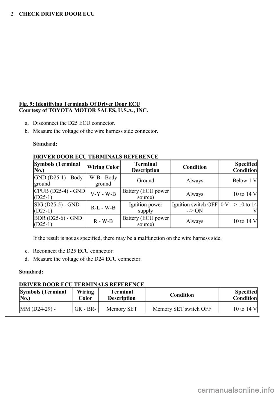
2.CHECK DRIVER DOOR ECU
Fig. 9: Identifying Terminals Of Driver Door ECU
Courtesy of TOYOTA MOTOR SALES, U.S.A., INC.
a. Disconnect the D25 ECU connector.
b. Measure the voltage of the wire harness side connector.
Standard:
DRIVER DOOR ECU TERMINALS REFERENCE
If the result is not as specified, there may be a malfunction on the wire harness side.
c. Reconnect the D25 ECU connector.
d. Measure the voltage of the D24 ECU connector.
Standard:
DRIVER DOOR ECU TERMINALS REFERENCE
Symbols (Terminal
No.)Wiring ColorTerminal
DescriptionConditionSpecified
Condition
GND (D25-1) - Body
groundW-B - Body
groundGroundAlwaysBelow 1 V
CPUB (D25-4) - GND
(D25-1)V-Y - W-BBattery (ECU power
source)Always10 to 14 V
SIG (D25-5) - GND
(D25-1)R-L - W-BIgnition power
supplyIgnition switch OFF
--> ON0 V --> 10 to 14
V
BDR (D25-6) - GND
(D25-1)R - W-BBattery (ECU power
source)Always10 to 14 V
Symbols (Terminal
No.)Wiring
ColorTerminal
DescriptionConditionSpecified
Condition
MM (D24-29) - GR - BR-Memory SET Memory SET switch OFF 10 to 14 V
Page 3925 of 4500

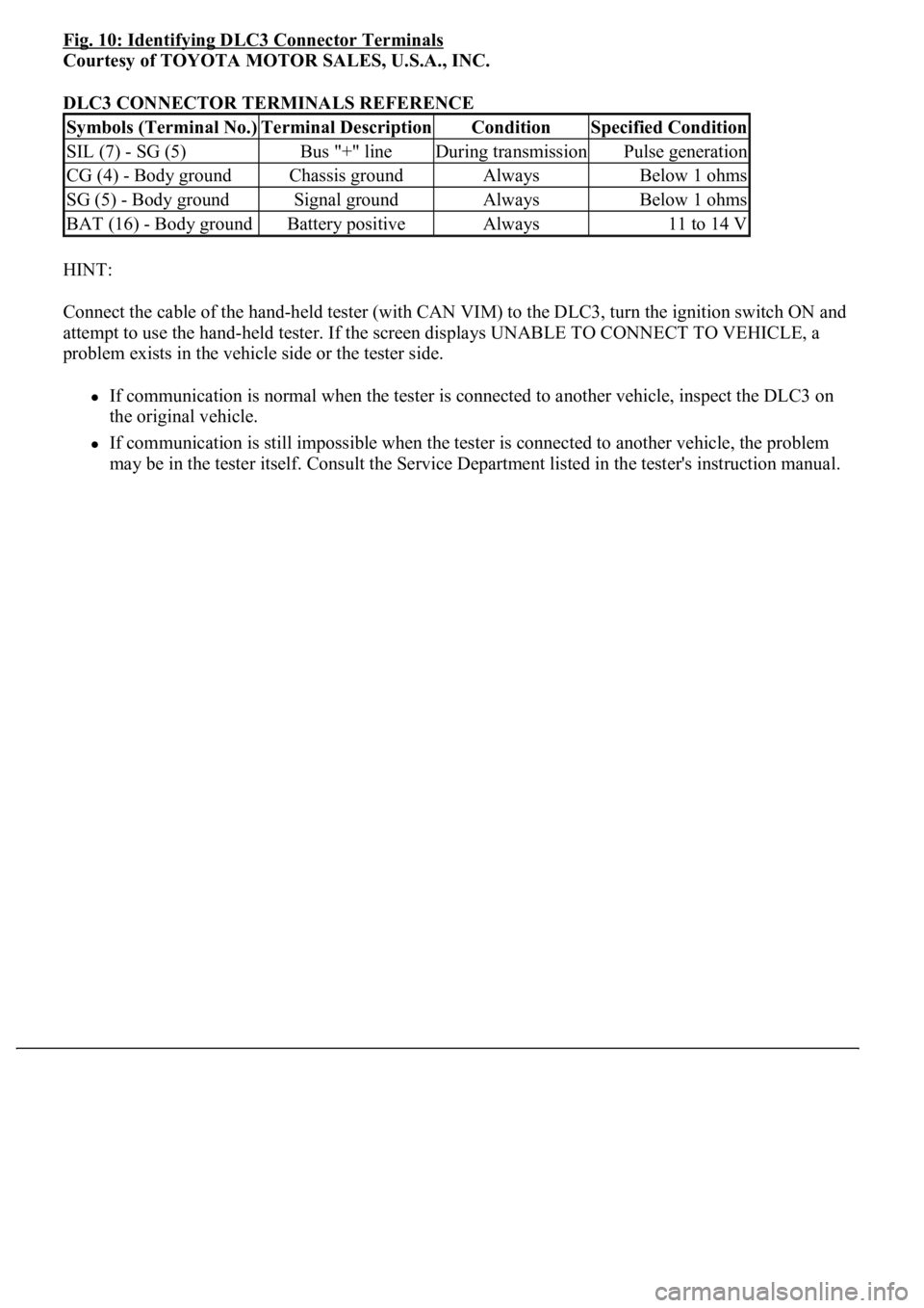
Fig. 10: Identifying DLC3 Connector Terminals
Courtesy of TOYOTA MOTOR SALES, U.S.A., INC.
DLC3 CONNECTOR TERMINALS REFERENCE
HINT:
Connect the cable of the hand-held tester (with CAN VIM) to the DLC3, turn the ignition switch ON and
attempt to use the hand-held tester. If the screen displays UNABLE TO CONNECT TO VEHICLE, a
problem exists in the vehicle side or the tester side.
If communication is normal when the tester is connected to another vehicle, inspect the DLC3 on
the original vehicle.
If communication is still impossible when the tester is connected to another vehicle, the problem
may be in the tester itself. Consult the Service Department listed in the tester's instruction manual.
Symbols (Terminal No.)Terminal DescriptionConditionSpecified Condition
SIL (7) - SG (5)Bus "+" lineDuring transmissionPulse generation
CG (4) - Body groundChassis groundAlwaysBelow 1 ohms
SG (5) - Body groundSignal groundAlwaysBelow 1 ohms
BAT (16) - Body groundBattery positiveAlways11 to 14 V
Page 3936 of 4500
NG: REPLACE FUSE
OK: GO TO NEXT STEP
2.INSPECT RELAY (D-IG1)
a. Remove the D-IG1 relay from the driver side J/B.
b. Measure the resistance of the relay.
Standard:
TESTER CONNECTION AND SPECIFIED CONDITION
Fig. 19: Identifying D
-IG1 Relay Terminals
Courtesy of TOYOTA MOTOR SALES, U.S.A., INC.
NG: REPLACE RELAY
OK: GO TO NEXT STEP
3.CHECK WIRE HARNESS (DRIVER DOOR ECU - BATTERY AND BODY GROUND)
Tester connectionSpecified condition
3 - 510 kohms or higher
3 - 5Below 1 ohms (when battery voltage is applied to terminals 1 and 2)
Page 3937 of 4500
a. Disconnect the D25 ECU connector.
b. Measure the voltage and resistance of the wire harness side connector.
Standard:
TESTER CONNECTION AND SPECIFIED CONDITION
Fig. 20: Identifying D25 Driver Door ECU Connector Terminals
Courtesy of TOYOTA MOTOR SALES, U.S.A., INC.
NG: REPAIR OR REPLACE HARNESS AND CONNECTOR
OK: PROCEED TO NEXT CIRCUIT INSPECTION SHOWN ON PROBLEM SYMPTOMS
TABLE
Tester connectionConditionSpecified condition
D25-4 (CPUB) - Body groundAlways10 to 14 V
D25-6 (BDR) - Body groundAlways10 to 14 V
D25-5 (SIG) - Body groundIgnition switch OFF --> ON0 V --> 10 to 14 V
D25-1 (GND) - Body groundAlwaysBelow 1 ohms
Page 3947 of 4500
OK: GO TO NEXT STEP
3.CHECK DRIVER SEAT ECU (SENSOR POWER SOURCE VOLTAGE)
a. Turn the ignition switch ON.
b. Measure the voltage of the ECU connector.
Standard:
TESTER CONNECTION AND SPECIFIED CONDITION
Fig. 26: Identifying D28 Driver Seat ECU Connector Terminals
Courtesy of TOYOTA MOTOR SALES, U.S.A., INC.
NG: REPLACE DRIVER SEAT ECU
OK: GO TO NEXT STEP
Tester connectionSpecified condition
D28-16 (PVCC) - Body ground8V