2003 LEXUS LS430 window
[x] Cancel search: windowPage 2181 of 4500
1.GENERAL
When the front and rear door system detects that the front and rear doors are ajar, it automatically
actuates the motor to fully close the front and rear doors.
Position detection switches are provided in the door closer mechanism in each of the front and rear
doors' lock assemblies to detect whether the front and rear doors are open, closed or ajar. If a
detection signal that indicates that a front or rear door is ajar is transmitted to the door ECU, the
door ECU actuates the door closer motor to fully close the door.
In this system, each door is independently controlled by the door ECU inside each door. The door
ECUs, which communicate via the BEAN, belong to the door bus.
A mechanical cancel mechanism is provided. This mechanism enables the front and rear doors to
be opened by operating either the outside or inside door handle while the door closer system is
operating. Through the function of the link and the lever that move together with the movement of
the door handle, the mechanical cancel mechanism cuts off the transmission of power from the
motor and disables the operation of the door closer system, thus enabling the door to be opened.
If the operation of the door close system is not completed within approximately 3 seconds (a
foreign object is jammed in window, for example), the door ECU will interpret it as a malfunction
and stop applying the current to the motor.
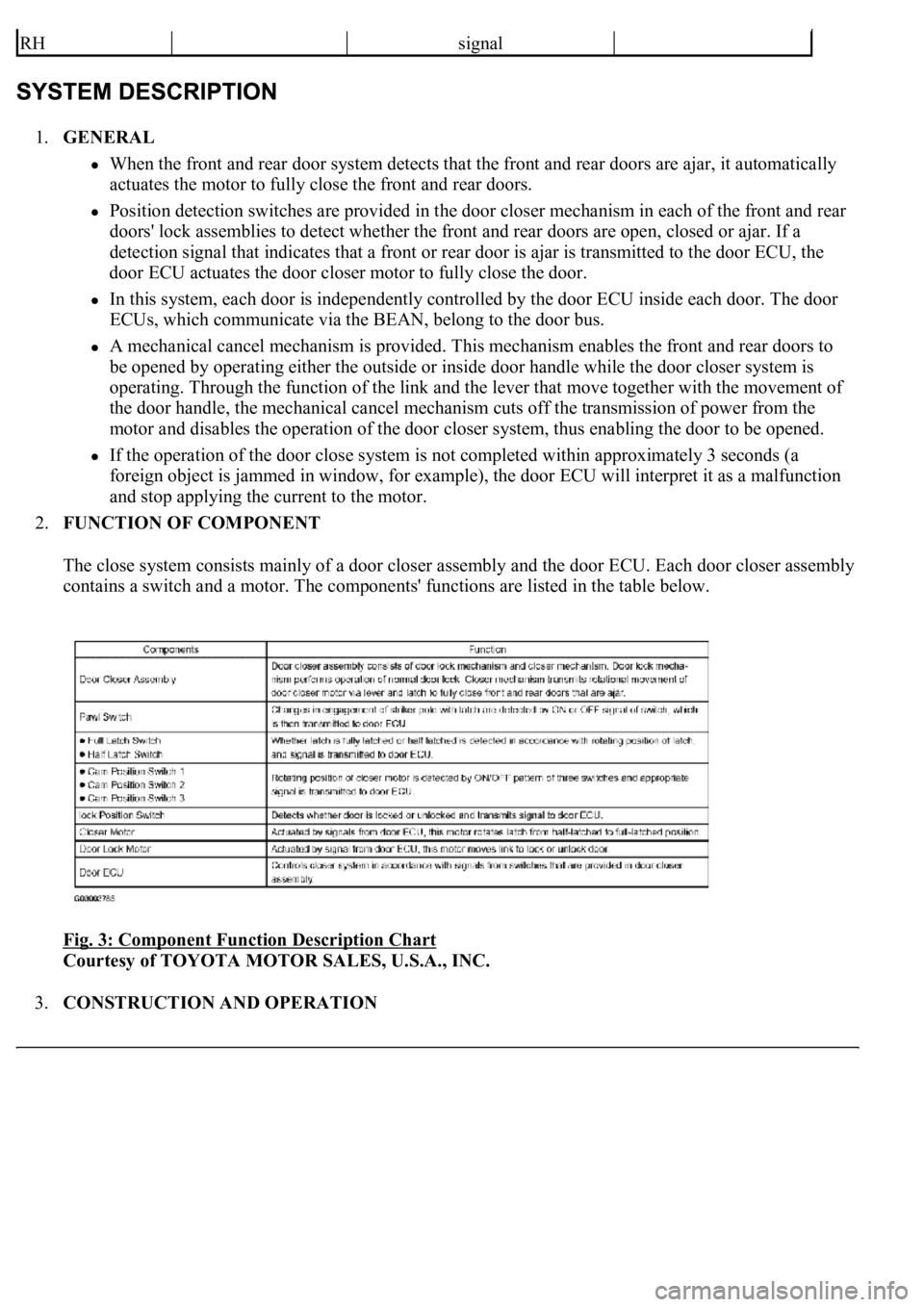
2.FUNCTION OF COMPONENT
The close system consists mainly of a door closer assembly and the door ECU. Each door closer assembly
contains a switch and a motor. The components' functions are listed in the table below.
Fig. 3: Component Function Description Chart
Courtesy of TOYOTA MOTOR SALES, U.S.A., INC.
3.CONSTRUCTION AND OPERATION
RHsignal
Page 2424 of 4500
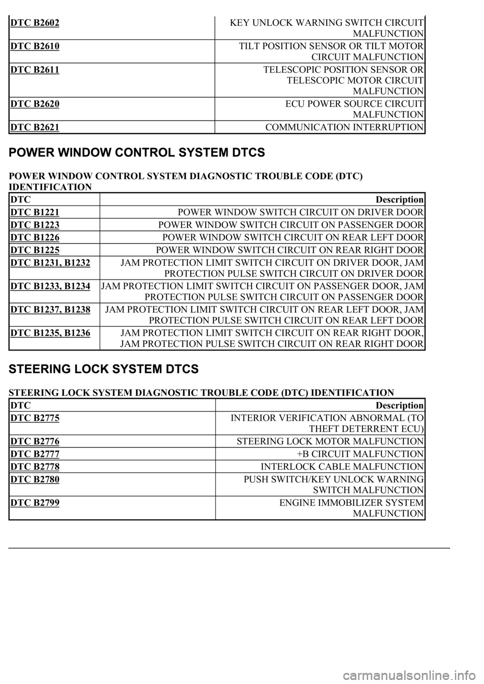
POWER WINDOW CONTROL SYSTEM DIAGNOSTIC TROUBLE CODE (DTC)
IDENTIFICATION
STEERING LOCK SYSTEM DIAGNOSTIC TROUBLE CODE (DTC) IDENTIFICATION
DTC B2602 KEY UNLOCK WARNING SWITCH CIRCUIT
MALFUNCTION
DTC B2610 TILT POSITION SENSOR OR TILT MOTOR
CIRCUIT MALFUNCTION
DTC B2611 TELESCOPIC POSITION SENSOR OR
TELESCOPIC MOTOR CIRCUIT
MALFUNCTION
DTC B2620 ECU POWER SOURCE CIRCUIT
MALFUNCTION
DTC B2621 COMMUNICATION INTERRUPTION
DTCDescription
DTC B1221 POWER WINDOW SWITCH CIRCUIT ON DRIVER DOOR
DTC B1223 POWER WINDOW SWITCH CIRCUIT ON PASSENGER DOOR
DTC B1226 POWER WINDOW SWITCH CIRCUIT ON REAR LEFT DOOR
DTC B1225 POWER WINDOW SWITCH CIRCUIT ON REAR RIGHT DOOR
DTC B1231, B1232 JAM PROTECTION LIMIT SWITCH CIRCUIT ON DRIVER DOOR, JAM
PROTECTION PULSE SWITCH CIRCUIT ON DRIVER DOOR
DTC B1233, B1234 JAM PROTECTION LIMIT SWITCH CIRCUIT ON PASSENGER DOOR, JAM
PROTECTION PULSE SWITCH CIRCUIT ON PASSENGER DOOR
DTC B1237, B1238 JAM PROTECTION LIMIT SWITCH CIRCUIT ON REAR LEFT DOOR, JAM
PROTECTION PULSE SWITCH CIRCUIT ON REAR LEFT DOOR
DTC B1235, B1236 JAM PROTECTION LIMIT SWITCH CIRCUIT ON REAR RIGHT DOOR,
JAM PROTECTION PULSE SWITCH CIRCUIT ON REAR RIGHT DOOR
DTCDescription
DTC B2775 INTERIOR VERIFICATION ABNORMAL (TO
THEFT DETERRENT ECU)
DTC B2776 STEERING LOCK MOTOR MALFUNCTION
DTC B2777 +B CIRCUIT MALFUNCTION
DTC B2778 INTERLOCK CABLE MALFUNCTION
DTC B2780 PUSH SWITCH/KEY UNLOCK WARNING
SWITCH MALFUNCTION
DTC B2799 ENGINE IMMOBILIZER SYSTEM
MALFUNCTION
Page 2627 of 4500
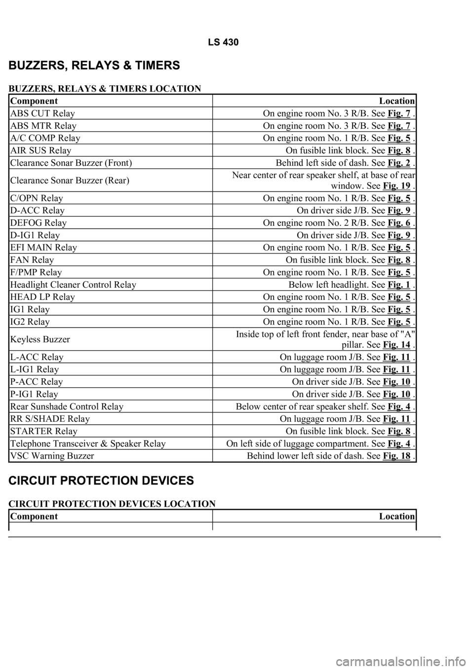
BUZZERS, RELAYS & TIMERS LOCATION
CIRCUIT PROTECTION DEVICES LOCATION
ComponentLocation
ABS CUT RelayOn engine room No. 3 R/B. See Fig. 7 .
ABS MTR RelayOn engine room No. 3 R/B. See Fig. 7 .
A/C COMP RelayOn engine room No. 1 R/B. See Fig. 5 .
AIR SUS RelayOn fusible link block. See Fig. 8 .
Clearance Sonar Buzzer (Front)Behind left side of dash. See Fig. 2 .
Clearance Sonar Buzzer (Rear)Near center of rear speaker shelf, at base of rear
window. See Fig. 19
.
C/OPN RelayOn engine room No. 1 R/B. See Fig. 5 .
D-ACC RelayOn driver side J/B. See Fig. 9 .
DEFOG RelayOn engine room No. 2 R/B. See Fig. 6 .
D-IG1 RelayOn driver side J/B. See Fig. 9 .
EFI MAIN RelayOn engine room No. 1 R/B. See Fig. 5 .
FAN RelayOn fusible link block. See Fig. 8 .
F/PMP RelayOn engine room No. 1 R/B. See Fig. 5 .
Headlight Cleaner Control RelayBelow left headlight. See Fig. 1 .
HEAD LP RelayOn engine room No. 1 R/B. See Fig. 5 .
IG1 RelayOn engine room No. 1 R/B. See Fig. 5 .
IG2 RelayOn engine room No. 1 R/B. See Fig. 5 .
Keyless BuzzerInside top of left front fender, near base of "A"
pillar. See Fig. 14
.
L-ACC RelayOn luggage room J/B. See Fig. 11 .
L-IG1 RelayOn luggage room J/B. See Fig. 11 .
P-ACC RelayOn driver side J/B. See Fig. 10 .
P-IG1 RelayOn driver side J/B. See Fig. 10 .
Rear Sunshade Control RelayBelow center of rear speaker shelf. See Fig. 4 .
RR S/SHADE RelayOn luggage room J/B. See Fig. 11 .
STARTER RelayOn fusible link block. See Fig. 8 .
Telephone Transceiver & Speaker RelayOn left side of luggage compartment. See Fig. 4 .
VSC Warning BuzzerBehind lower left side of dash. See Fig. 18 .
ComponentLocation
Page 2630 of 4500
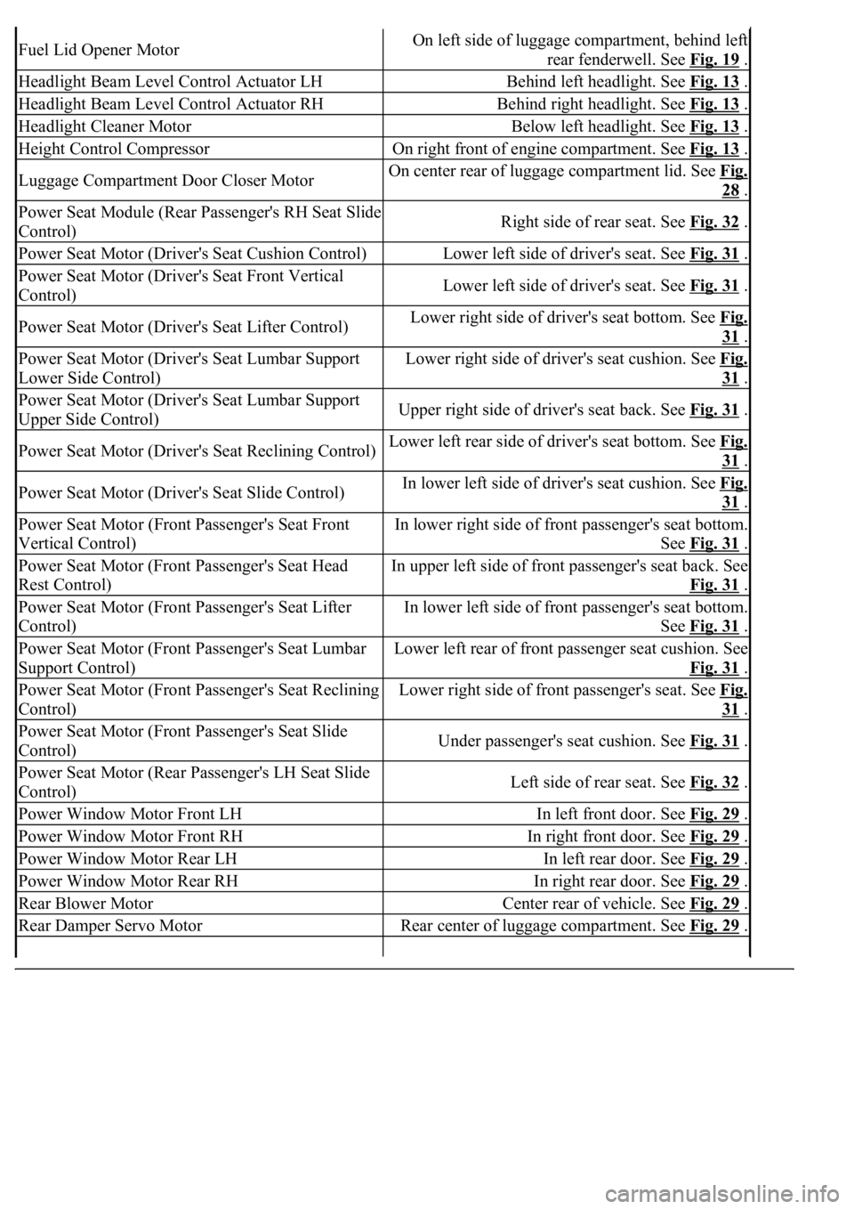
Fuel Lid Opener MotorOn left side of luggage compartment, behind left
rear fenderwell. See Fig. 19
.
Headlight Beam Level Control Actuator LHBehind left headlight. See Fig. 13 .
Headlight Beam Level Control Actuator RHBehind right headlight. See Fig. 13 .
Headlight Cleaner MotorBelow left headlight. See Fig. 13 .
Height Control CompressorOn right front of engine compartment. See Fig. 13 .
Luggage Compartment Door Closer MotorOn center rear of luggage compartment lid. See Fig.
28 .
Power Seat Module (Rear Passenger's RH Seat Slide
Control)Right side of rear seat. See Fig. 32 .
Power Seat Motor (Driver's Seat Cushion Control)Lower left side of driver's seat. See Fig. 31 .
Power Seat Motor (Driver's Seat Front Vertical
Control)Lower left side of driver's seat. See Fig. 31 .
Power Seat Motor (Driver's Seat Lifter Control)Lower right side of driver's seat bottom. See Fig.
31 .
Power Seat Motor (Driver's Seat Lumbar Support
Lower Side Control)Lower right side of driver's seat cushion. See Fig.
31 .
Power Seat Motor (Driver's Seat Lumbar Support
Upper Side Control)Upper right side of driver's seat back. See Fig. 31 .
Power Seat Motor (Driver's Seat Reclining Control)Lower left rear side of driver's seat bottom. See Fig.
31 .
Power Seat Motor (Driver's Seat Slide Control)In lower left side of driver's seat cushion. See Fig.
31 .
Power Seat Motor (Front Passenger's Seat Front
Vertical Control)In lower right side of front passenger's seat bottom.
See Fig. 31
.
Power Seat Motor (Front Passenger's Seat Head
Rest Control)In upper left side of front passenger's seat back. See
Fig. 31
.
Power Seat Motor (Front Passenger's Seat Lifter
Control)In lower left side of front passenger's seat bottom.
See Fig. 31
.
Power Seat Motor (Front Passenger's Seat Lumbar
Support Control)Lower left rear of front passenger seat cushion. See
Fig. 31
.
Power Seat Motor (Front Passenger's Seat Reclining
Control)Lower right side of front passenger's seat. See Fig.
31 .
Power Seat Motor (Front Passenger's Seat Slide
Control)Under passenger's seat cushion. See Fig. 31 .
Power Seat Motor (Rear Passenger's LH Seat Slide
Control)Left side of rear seat. See Fig. 32 .
Power Window Motor Front LHIn left front door. See Fig. 29 .
Power Window Motor Front RHIn right front door. See Fig. 29 .
Power Window Motor Rear LHIn left rear door. See Fig. 29 .
Power Window Motor Rear RHIn right rear door. See Fig. 29 .
Rear Blower MotorCenter rear of vehicle. See Fig. 29 .
Rear Damper Servo MotorRear center of luggage compartment. See Fig. 29 .
Page 2631 of 4500
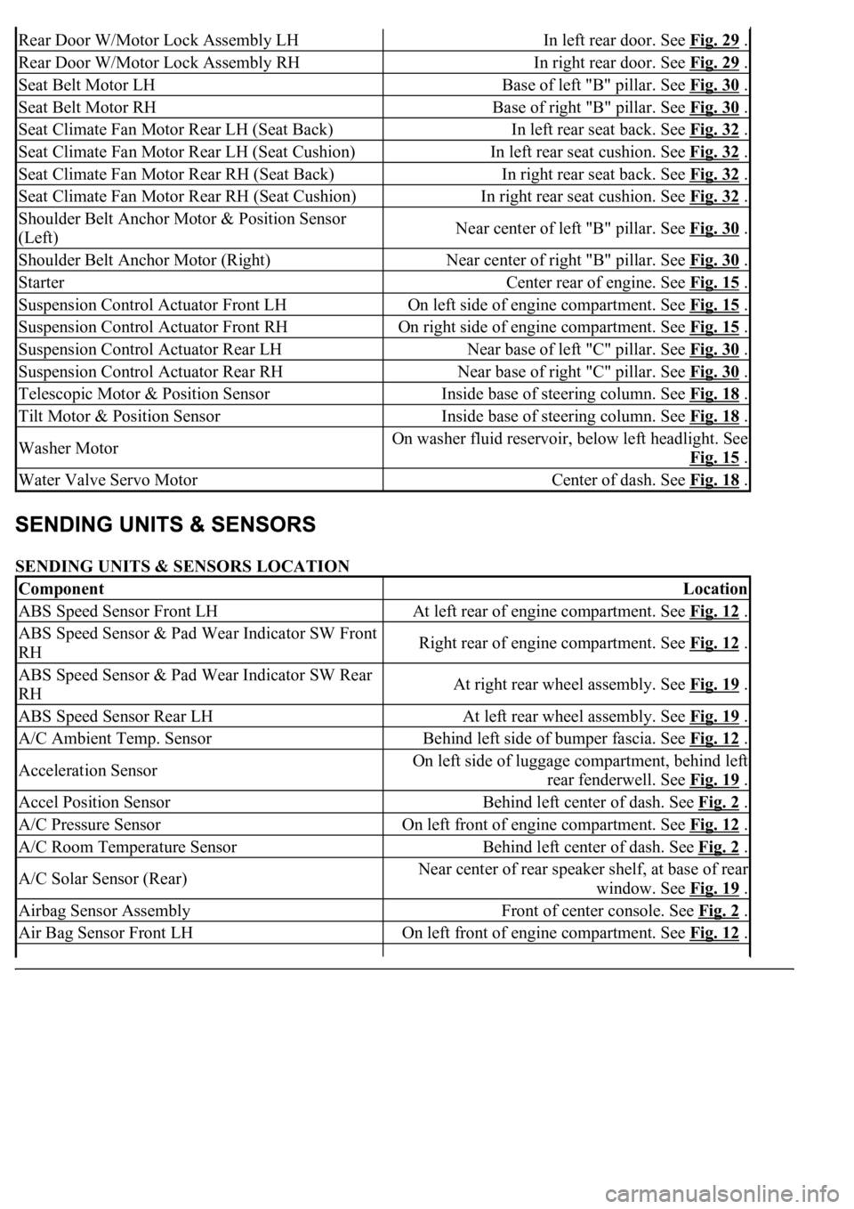
SENDING UNITS & SENSORS LOCATION
Rear Door W/Motor Lock Assembly LHIn left rear door. See Fig. 29 .
Rear Door W/Motor Lock Assembly RHIn right rear door. See Fig. 29 .
Seat Belt Motor LHBase of left "B" pillar. See Fig. 30 .
Seat Belt Motor RHBase of right "B" pillar. See Fig. 30 .
Seat Climate Fan Motor Rear LH (Seat Back)In left rear seat back. See Fig. 32 .
Seat Climate Fan Motor Rear LH (Seat Cushion)In left rear seat cushion. See Fig. 32 .
Seat Climate Fan Motor Rear RH (Seat Back)In right rear seat back. See Fig. 32 .
Seat Climate Fan Motor Rear RH (Seat Cushion)In right rear seat cushion. See Fig. 32 .
Shoulder Belt Anchor Motor & Position Sensor
(Left)Near center of left "B" pillar. See Fig. 30 .
Shoulder Belt Anchor Motor (Right)Near center of right "B" pillar. See Fig. 30 .
StarterCenter rear of engine. See Fig. 15 .
Suspension Control Actuator Front LHOn left side of engine compartment. See Fig. 15 .
Suspension Control Actuator Front RHOn right side of engine compartment. See Fig. 15 .
Suspension Control Actuator Rear LHNear base of left "C" pillar. See Fig. 30 .
Suspension Control Actuator Rear RHNear base of right "C" pillar. See Fig. 30 .
Telescopic Motor & Position SensorInside base of steering column. See Fig. 18 .
Tilt Motor & Position SensorInside base of steering column. See Fig. 18 .
Washer MotorOn washer fluid reservoir, below left headlight. See
Fig. 15
.
Water Valve Servo MotorCenter of dash. See Fig. 18 .
ComponentLocation
ABS Speed Sensor Front LHAt left rear of engine compartment. See Fig. 12 .
ABS Speed Sensor & Pad Wear Indicator SW Front
RHRight rear of engine compartment. See Fig. 12 .
ABS Speed Sensor & Pad Wear Indicator SW Rear
RHAt right rear wheel assembly. See Fig. 19 .
ABS Speed Sensor Rear LHAt left rear wheel assembly. See Fig. 19 .
A/C Ambient Temp. SensorBehind left side of bumper fascia. See Fig. 12 .
Acceleration SensorOn left side of luggage compartment, behind left
rear fenderwell. See Fig. 19
.
Accel Position SensorBehind left center of dash. See Fig. 2 .
A/C Pressure SensorOn left front of engine compartment. See Fig. 12 .
A/C Room Temperature SensorBehind left center of dash. See Fig. 2 .
A/C Solar Sensor (Rear)Near center of rear speaker shelf, at base of rear
window. See Fig. 19
.
Airbag Sensor AssemblyFront of center console. See Fig. 2 .
Air Bag Sensor Front LHOn left front of engine compartment. See Fig. 12 .
Page 2636 of 4500
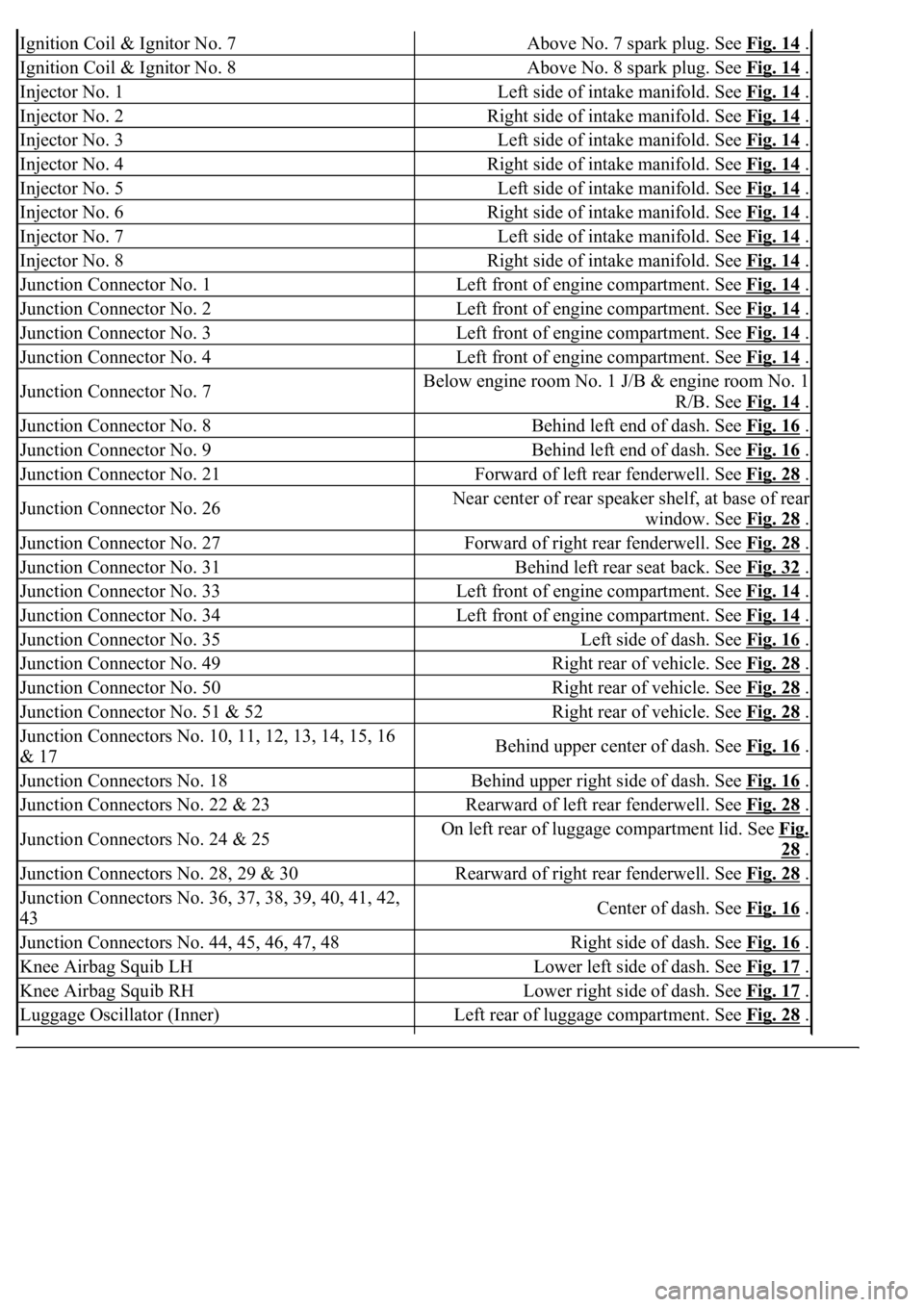
Ignition Coil & Ignitor No. 7Above No. 7 spark plug. See Fig. 14 .
Ignition Coil & Ignitor No. 8Above No. 8 spark plug. See Fig. 14 .
Injector No. 1Left side of intake manifold. See Fig. 14 .
Injector No. 2Right side of intake manifold. See Fig. 14 .
Injector No. 3Left side of intake manifold. See Fig. 14 .
Injector No. 4Right side of intake manifold. See Fig. 14 .
Injector No. 5Left side of intake manifold. See Fig. 14 .
Injector No. 6Right side of intake manifold. See Fig. 14 .
Injector No. 7Left side of intake manifold. See Fig. 14 .
Injector No. 8Right side of intake manifold. See Fig. 14 .
Junction Connector No. 1Left front of engine compartment. See Fig. 14 .
Junction Connector No. 2Left front of engine compartment. See Fig. 14 .
Junction Connector No. 3Left front of engine compartment. See Fig. 14 .
Junction Connector No. 4Left front of engine compartment. See Fig. 14 .
Junction Connector No. 7Below engine room No. 1 J/B & engine room No. 1
R/B. See Fig. 14
.
Junction Connector No. 8Behind left end of dash. See Fig. 16 .
Junction Connector No. 9Behind left end of dash. See Fig. 16 .
Junction Connector No. 21Forward of left rear fenderwell. See Fig. 28 .
Junction Connector No. 26Near center of rear speaker shelf, at base of rear
window. See Fig. 28
.
Junction Connector No. 27Forward of right rear fenderwell. See Fig. 28 .
Junction Connector No. 31Behind left rear seat back. See Fig. 32 .
Junction Connector No. 33Left front of engine compartment. See Fig. 14 .
Junction Connector No. 34Left front of engine compartment. See Fig. 14 .
Junction Connector No. 35Left side of dash. See Fig. 16 .
Junction Connector No. 49Right rear of vehicle. See Fig. 28 .
Junction Connector No. 50Right rear of vehicle. See Fig. 28 .
Junction Connector No. 51 & 52Right rear of vehicle. See Fig. 28 .
<002d0058005100460057004c00520051000300260052005100510048004600570052005500560003003100520011000300140013000f000300140014000f000300140015000f000300140016000f000300140017000f000300140018000f00030014001900
03[
& 17Behind upper center of dash. See Fig. 16 .
Junction Connectors No. 18Behind upper right side of dash. See Fig. 16 .
Junction Connectors No. 22 & 23Rearward of left rear fenderwell. See Fig. 28 .
Junction Connectors No. 24 & 25On left rear of luggage compartment lid. See Fig.
28 .
Junction Connectors No. 28, 29 & 30Rearward of right rear fenderwell. See Fig. 28 .
<002d0058005100460057004c00520051000300260052005100510048004600570052005500560003003100520011000300160019000f00030016001a000f00030016001b000f00030016001c000f000300170013000f000300170014000f00030017001500
0f0003[
43Center of dash. See Fig. 16 .
Junction Connectors No. 44, 45, 46, 47, 48Right side of dash. See Fig. 16 .
Knee Airbag Squib LHLower left side of dash. See Fig. 17 .
Knee Airbag Squib RHLower right side of dash. See Fig. 17 .
Luggage Oscillator (Inner)Left rear of luggage compartment. See Fig. 28 .
Page 2637 of 4500
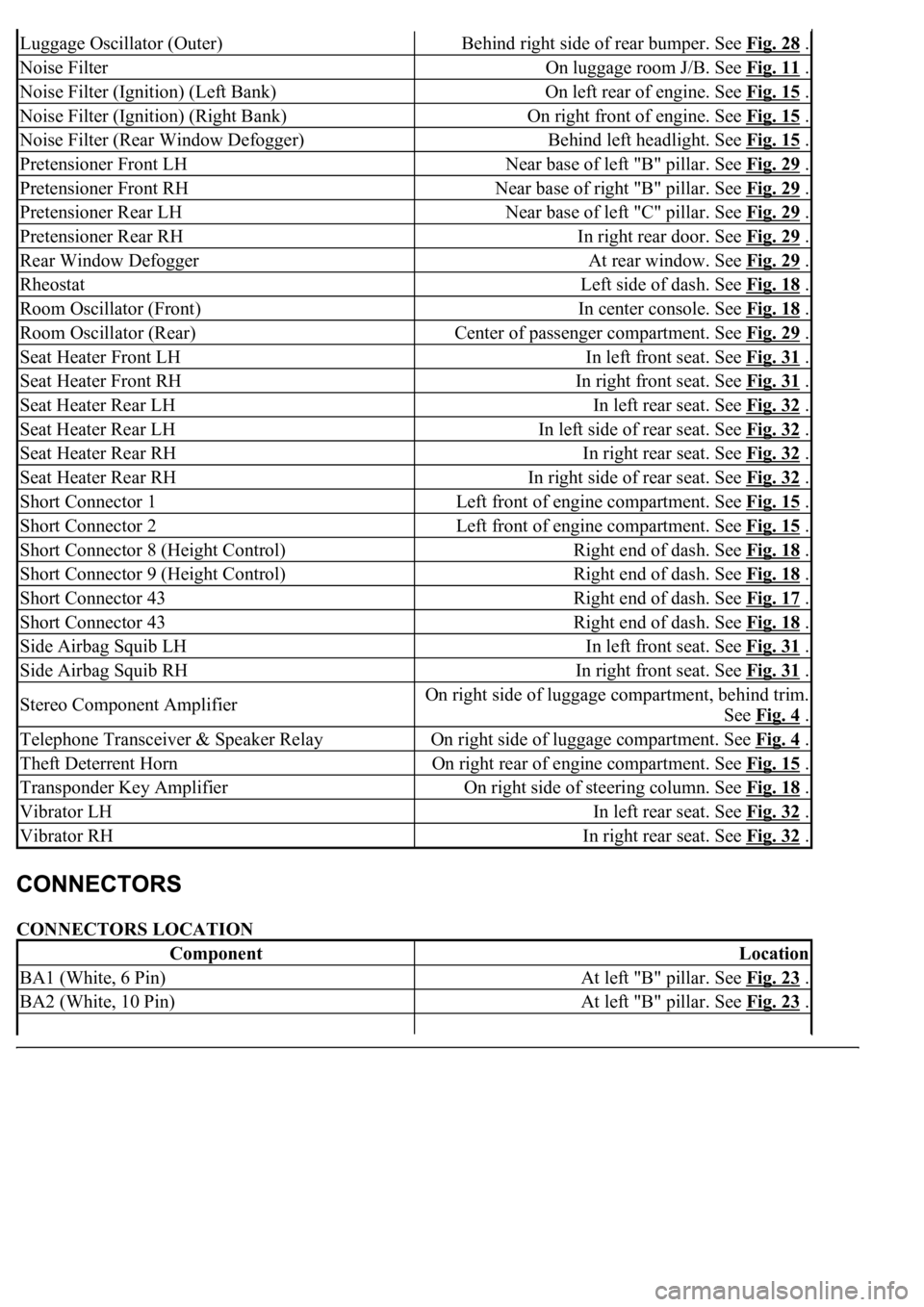
CONNECTORS LOCATION
Luggage Oscillator (Outer)Behind right side of rear bumper. See Fig. 28 .
Noise FilterOn luggage room J/B. See Fig. 11 .
Noise Filter (Ignition) (Left Bank)On left rear of engine. See Fig. 15 .
Noise Filter (Ignition) (Right Bank)On right front of engine. See Fig. 15 .
Noise Filter (Rear Window Defogger)Behind left headlight. See Fig. 15 .
Pretensioner Front LHNear base of left "B" pillar. See Fig. 29 .
Pretensioner Front RHNear base of right "B" pillar. See Fig. 29 .
Pretensioner Rear LHNear base of left "C" pillar. See Fig. 29 .
Pretensioner Rear RHIn right rear door. See Fig. 29 .
Rear Window DefoggerAt rear window. See Fig. 29 .
RheostatLeft side of dash. See Fig. 18 .
Room Oscillator (Front)In center console. See Fig. 18 .
Room Oscillator (Rear)Center of passenger compartment. See Fig. 29 .
Seat Heater Front LHIn left front seat. See Fig. 31 .
Seat Heater Front RHIn right front seat. See Fig. 31 .
Seat Heater Rear LHIn left rear seat. See Fig. 32 .
Seat Heater Rear LHIn left side of rear seat. See Fig. 32 .
Seat Heater Rear RHIn right rear seat. See Fig. 32 .
Seat Heater Rear RHIn right side of rear seat. See Fig. 32 .
Short Connector 1Left front of engine compartment. See Fig. 15 .
Short Connector 2Left front of engine compartment. See Fig. 15 .
Short Connector 8 (Height Control)Right end of dash. See Fig. 18 .
Short Connector 9 (Height Control)Right end of dash. See Fig. 18 .
Short Connector 43Right end of dash. See Fig. 17 .
Short Connector 43Right end of dash. See Fig. 18 .
Side Airbag Squib LHIn left front seat. See Fig. 31 .
Side Airbag Squib RHIn right front seat. See Fig. 31 .
Stereo Component AmplifierOn right side of luggage compartment, behind trim.
See Fig. 4
.
Telephone Transceiver & Speaker RelayOn right side of luggage compartment. See Fig. 4 .
Theft Deterrent HornOn right rear of engine compartment. See Fig. 15 .
Transponder Key AmplifierOn right side of steering column. See Fig. 18 .
Vibrator LHIn left rear seat. See Fig. 32 .
Vibrator RHIn right rear seat. See Fig. 32 .
ComponentLocation
BA1 (White, 6 Pin)At left "B" pillar. See Fig. 23 .
BA2 (White, 10 Pin)At left "B" pillar. See Fig. 23 .
Page 2982 of 4500
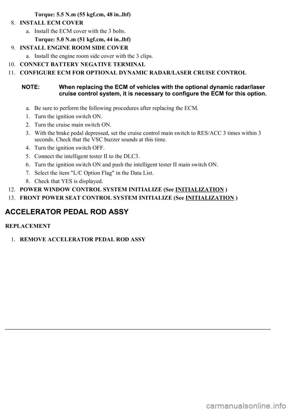
Torque: 5.5 N.m (55 kgf.cm, 48 in..lbf)
8.INSTALL ECM COVER
a. Install the ECM cover with the 3 bolts.
Torque: 5.0 N.m (51 kgf.cm, 44 in..lbf)
9.INSTALL ENGINE ROOM SIDE COVER
a. Install the engine room side cover with the 3 clips.
10.CONNECT BATTERY NEGATIVE TERMINAL
11.CONFIGURE ECM FOR OPTIONAL DYNAMIC RADAR/LASER CRUISE CONTROL
a. Be sure to perform the following procedures after replacing the ECM.
1. Turn the ignition switch ON.
2. Turn the cruise main switch ON.
3. With the brake pedal depressed, set the cruise control main switch to RES/ACC 3 times within 3
seconds. Check that the VSC buzzer sounds at this time.
4. Turn the ignition switch OFF.
5. Connect the intelligent tester II to the DLC3.
6. Turn the ignition switch ON and push the intelligent tester II main switch ON.
7. Select the item "L/C Option Flag" in the Data List.
8. Check that YES is displayed.
12.POWER WINDOW CONTROL SYSTEM INITIALIZE (See INITIALIZATION
)
13.FRONT POWER SEAT CONTROL SYSTEM INITIALIZE (See INITIALIZATION
)
REPLACEMENT
1.REMOVE ACCELERATOR PEDAL ROD ASSY