Page 2564 of 4500
Fig. 33: Connecting Hand-Held Tester To DLC3
Courtesy of TOYOTA MOTOR SALES, U.S.A., INC.
1.Constant speed control mode and vehicle-to-vehicle distance control mode:
If the following conditions are detected while the dynamic radar cruise control is in operation, the system
clears the stored vehicle speed in the ECM and cancels the dynamic radar cruise control operation.
Fig. 34: Identifying CRUISE Main Indicator Light And Master Warning Light
Page 2565 of 4500
Courtesy of TOYOTA MOTOR SALES, U.S.A., INC.
Fig. 35: Fail
-Safe Chart
Courtesy of TOYOTA MOTOR SALES, U.S.A., INC.
2.Only in the vehicle-to-vehicle distance control mode:
If the following conditions are detected while the dynamic radar cruise control is in operation, the system
clears the stored vehicle speed in the ECM and cancels the dynamic radar cruise control operation.
Fig. 36: Identifying CRUISE Main Indicator Light And Master Warning Light
Courtesy of TOYOTA MOTOR SALES, U.S.A., INC.
Fig. 37: Fail
-Safe Chart
Courtesy of TOYOTA MOTOR SALES, U.S.A., INC.
3.Only in the vehicle-to-vehicle distance control mode:
If the following conditions are detected while the dynamic radar cruise control is in operation, the system
maintains the stored vehicle speed in the ECM and cancels the d
ynamic radar cruise control operation.
Page 2566 of 4500
Fig. 38: Identifying CRUISE Main Indicator Light And Master Warning Light
Courtesy of TOYOTA MOTOR SALES, U.S.A., INC.
Fig. 39: Fail
-Safe Chart (1 Of 2)
Courtesy of TOYOTA MOTOR SALES, U.S.A., INC.
4.Constant speed control mode and vehicle-to-vehicle distance control mode:
If the following conditions are detected while the dynamic radar cruise control is in operation, the system
clears the stored vehicle speed and cancels the dynamic radar cruise control operation.
HINT:
In the vehicle-to-vehicle distance control mode, the stored vehicle speed in the ECM is maintained.
Fig. 40: Fail
-Safe Chart (2 Of 2)
Courtesy of TOYOTA MOTOR SALES, U.S.A., INC.
Page 2570 of 4500

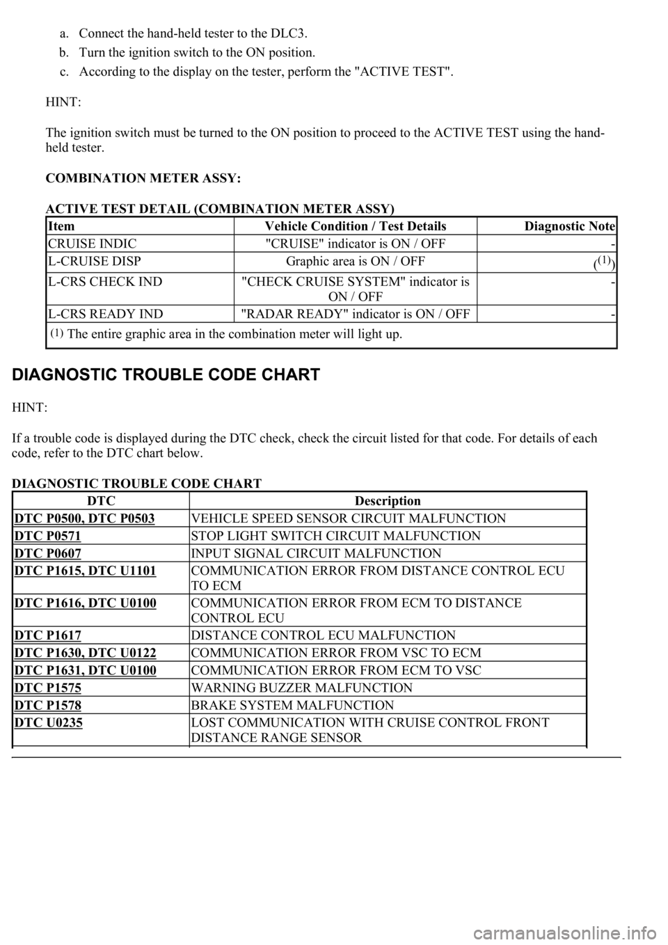
a. Connect the hand-held tester to the DLC3.
b. Turn the ignition switch to the ON position.
c. According to the display on the tester, perform the "ACTIVE TEST".
HINT:
The ignition switch must be turned to the ON position to proceed to the ACTIVE TEST using the hand-
held tester.
COMBINATION METER ASSY:
ACTIVE TEST DETAIL (COMBINATION METER ASSY)
HINT:
If a trouble code is displayed during the DTC check, check the circuit listed for that code. For details of each
code, refer to the DTC chart below.
DIAGNOSTIC TROUBLE CODE CHART
ItemVehicle Condition / Test DetailsDiagnostic Note
CRUISE INDIC"CRUISE" indicator is ON / OFF-
L-CRUISE DISPGraphic area is ON / OFF((1))
L-CRS CHECK IND"CHECK CRUISE SYSTEM" indicator is
ON / OFF-
L-CRS READY IND"RADAR READY" indicator is ON / OFF-
(1)The entire graphic area in the combination meter will light up.
DTCDescription
DTC P0500, DTC P0503VEHICLE SPEED SENSOR CIRCUIT MALFUNCTION
DTC P0571STOP LIGHT SWITCH CIRCUIT MALFUNCTION
DTC P0607INPUT SIGNAL CIRCUIT MALFUNCTION
DTC P1615, DTC U1101COMMUNICATION ERROR FROM DISTANCE CONTROL ECU
TO ECM
DTC P1616, DTC U0100COMMUNICATION ERROR FROM ECM TO DISTANCE
CONTROL ECU
DTC P1617DISTANCE CONTROL ECU MALFUNCTION
DTC P1630, DTC U0122COMMUNICATION ERROR FROM VSC TO ECM
DTC P1631, DTC U0100COMMUNICATION ERROR FROM ECM TO VSC
DTC P1575WARNING BUZZER MALFUNCTION
DTC P1578BRAKE SYSTEM MALFUNCTION
DTC U0235LOST COMMUNICATION WITH CRUISE CONTROL FRONT
DISTANCE RANGE SENSOR
Page 2575 of 4500
Fig. 46: Wiring Diagram - Stop Light Switch Circuit Malfunction
Courtesy of TOYOTA MOTOR SALES, U.S.A., INC.
INSPECTION PROCEDURE
1.READ VALUE ON HAND-HELD TESTER
a. Connect the han
d-held tester to the DLC3.
Page 2576 of 4500

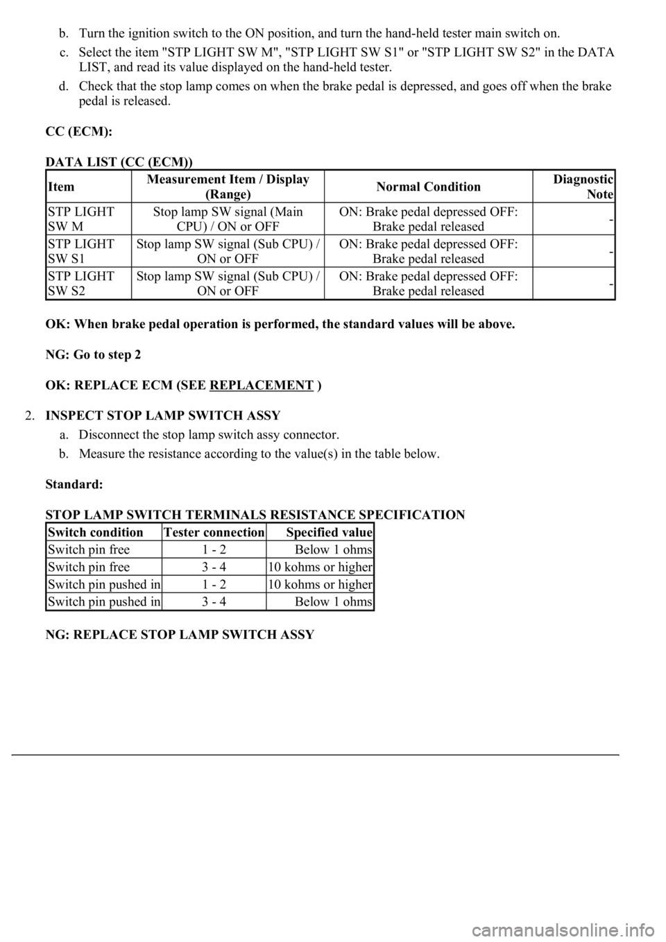
b. Turn the ignition switch to the ON position, and turn the hand-held tester main switch on.
c. Select the item "STP LIGHT SW M", "STP LIGHT SW S1" or "STP LIGHT SW S2" in the DATA
LIST, and read its value displayed on the hand-held tester.
d. Check that the stop lamp comes on when the brake pedal is depressed, and goes off when the brake
pedal is released.
CC (ECM):
DATA LIST (CC (ECM))
OK: When brake pedal operation is performed, the standard values will be above.
NG: Go to step 2
OK: REPLACE ECM (SEE REPLACEMENT
)
2.INSPECT STOP LAMP SWITCH ASSY
a. Disconnect the stop lamp switch assy connector.
b. Measure the resistance according to the value(s) in the table below.
Standard:
STOP LAMP SWITCH TERMINALS RESISTANCE SPECIFICATION
NG: REPLACE STOP LAMP SWITCH ASSY
ItemMeasurement Item / Display
(Range)Normal ConditionDiagnostic
Note
STP LIGHT
SW MStop lamp SW signal (Main
CPU) / ON or OFFON: Brake pedal depressed OFF:
Brake pedal released-
STP LIGHT
SW S1Stop lamp SW signal (Sub CPU) /
ON or OFFON: Brake pedal depressed OFF:
Brake pedal released-
STP LIGHT
SW S2Stop lamp SW signal (Sub CPU) /
ON or OFFON: Brake pedal depressed OFF:
Brake pedal released-
Switch conditionTester connectionSpecified value
Switch pin free1 - 2Below 1 ohms
Switch pin free3 - 410 kohms or higher
Switch pin pushed in1 - 210 kohms or higher
Switch pin pushed in3 - 4Below 1 ohms
Page 2584 of 4500

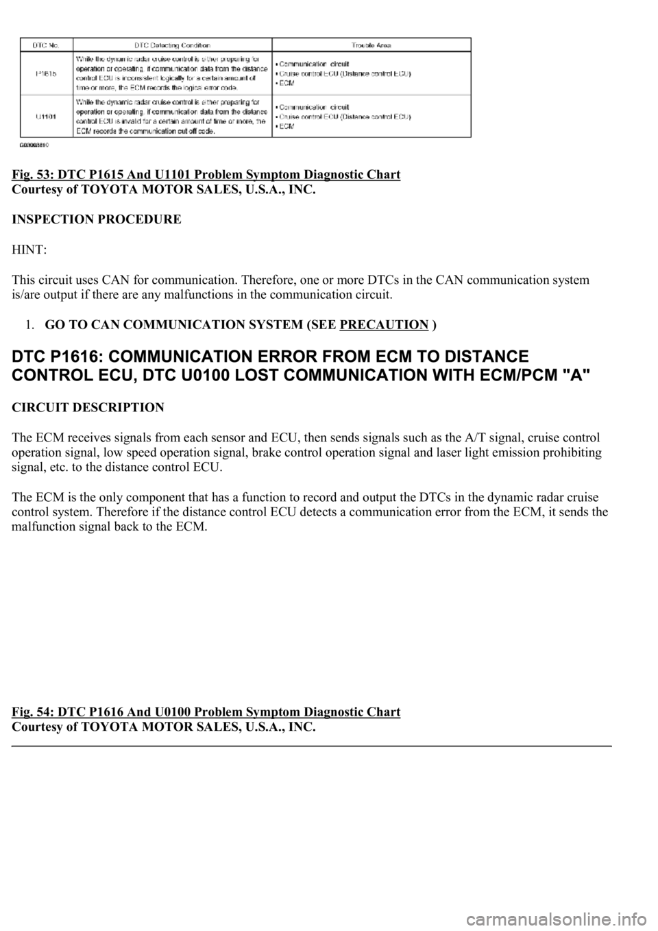
Fig. 53: DTC P1615 And U1101 Problem Symptom Diagnostic Chart
Courtesy of TOYOTA MOTOR SALES, U.S.A., INC.
INSPECTION PROCEDURE
HINT:
This circuit uses CAN for communication. Therefore, one or more DTCs in the CAN communication system
is/are output if there are any malfunctions in the communication circuit.
1.GO TO CAN COMMUNICATION SYSTEM (SEE PRECAUTION
)
CIRCUIT DESCRIPTION
The ECM receives signals from each sensor and ECU, then sends signals such as the A/T signal, cruise control
<005200530048005500440057004c0052005100030056004c004a00510044004f000f0003004f0052005a0003005600530048004800470003005200530048005500440057004c0052005100030056004c004a00510044004f000f0003004500550044004e00
480003004600520051005700550052004f0003005200530048[ration signal and laser light emission prohibiting
signal, etc. to the distance control ECU.
<0037004b004800030028002600300003004c005600030057004b0048000300520051004f005c000300460052005000530052005100480051005700030057004b004400570003004b0044005600030044000300490058005100460057004c00520051000300
57005200030055004800460052005500470003004400510047[ output the DTCs in the dynamic radar cruise
control system. Therefore if the distance control ECU detects a communication error from the ECM, it sends the
malfunction signal back to the ECM.
Fig. 54: DTC P1616 And U0100 Problem Symptom Diagnostic Chart
Courtesy of TOYOTA MOTOR SALES, U.S.A., INC.
Page 2585 of 4500

INSPECTION PROCEDURE
HINT:
This circuit uses CAN for communication. Therefore, if there are any malfunctions in the communication
circuit, one or more DTCs in the CAN communication system is/are output.
1.GO TO CAN COMMUNICATION SYSTEM (SEE PRECAUTION
)
CIRCUIT DESCRIPTION
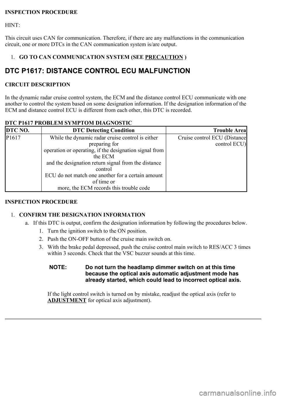
In the dynamic radar cruise control system, the ECM and the distance control ECU communicate with one
another to control the system based on some designation information. If the designation information of the
ECM and distance control ECU is different from each other, this DTC is recorded.
DTC P1617 PROBLEM SYMPTOM DIAGNOSTIC
INSPECTION PROCEDURE
1.CONFIRM THE DESIGNATION INFORMATION
a. If this DTC is output, confirm the designation information by following the procedures below.
1. Turn the ignition switch to the ON position.
2. Push the ON-OFF button of the cruise main switch on.
3. With the brake pedal depressed, push the cruise control main switch to RES/ACC 3 times
within 3 seconds. Check that the VSC buzzer sounds at this time.
If the light control switch is turned on by mistake, readjust the optical axis (refer to
ADJUSTMENT
for optical axis adjustment).
DTC NO.DTC Detecting ConditionTrouble Area
P1617While the dynamic radar cruise control is either
preparing for
operation or operating, if the designation signal from
the ECM
and the designation return signal from the distance
control
ECU do not match one another for a certain amount
of time or
more, the ECM records this trouble codeCruise control ECU (Distance
control ECU)