Page 2760 of 4500

TYPICAL ENABLING CONDITIONS
The stop light switch remains on during GO and STOP 10 times.
GO and STOP is defined as follows;
TYPICAL ENABLING CONDITIONS TABLE
TYPICAL MALFUNCTION THRESHOLDS
TYPICAL MALFUNCTION THRESHOLDS TABLE
WIRING DIAGRAM
See DTC P0504, P0571: BRAKE SWITCH "A"/"B" CORRELATION, BRAKE SWITCH "A"
CIRCUIT .
INSPECTION PROCEDURE
HINT:
According to the DATA LIST displayed by the hand-held tester, you can read the value of the switch, sensor,
actuator and so on without parts removal. Reading the DATA LIST as the first step of troubleshooting is one
method to shorten labor time.
a. Turn the ignition switch off.
b. Connect the hand-held tester together with the CAN VIM (controller area network vehicle interface
module) to the DLC3.
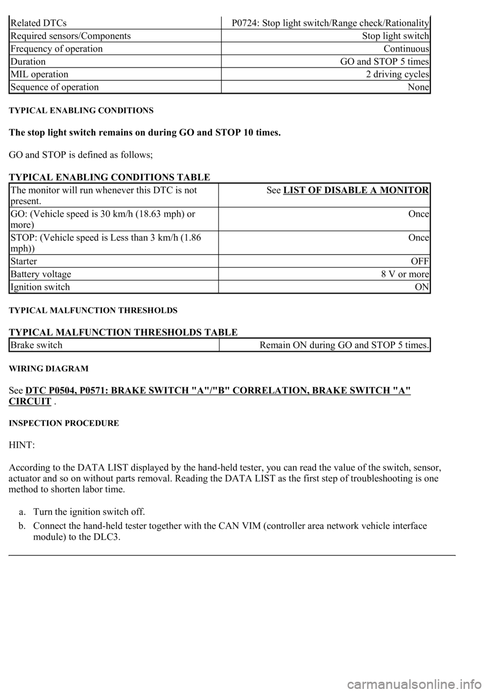
Related DTCsP0724: Stop light switch/Range check/Rationality
Required sensors/ComponentsStop light switch
Frequency of operationContinuous
DurationGO and STOP 5 times
MIL operation2 driving cycles
Sequence of operationNone
The monitor will run whenever this DTC is not
present.See LIST OF DISABLE A MONITOR
GO: (Vehicle speed is 30 km/h (18.63 mph) or
more)Once
STOP: (Vehicle speed is Less than 3 km/h (1.86
mph))Once
StarterOFF
Battery voltage8 V or more
Ignition switchON
Brake switchRemain ON during GO and STOP 5 times.
Page 2874 of 4500

a. Warm up the engine.
b. Turn the ignition switch off.
c. Connect the hand-held tester together with the CAN VIM (controller area network vehicle interface
module) to the DLC3.
d. Turn the ignition switch to the ON position.
e. Push the "ON" button of the hand-held tester.
f. Clear the DTC.
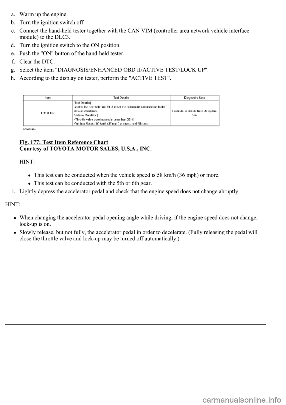
g. Select the item "DIAGNOSIS/ENHANCED OBD II/ACTIVE TEST/LOCK UP".
h. According to the display on tester, perform the "ACTIVE TEST".
Fig. 177: Test Item Reference Chart
Courtesy of TOYOTA MOTOR SALES, U.S.A., INC.
HINT:
This test can be conducted when the vehicle speed is 58 km/h (36 mph) or more.
This test can be conducted with the 5th or 6th gear.
i. Lightly depress the accelerator pedal and check that the engine speed does not change abruptly.
HINT:
When changing the accelerator pedal opening angle while driving, if the engine speed does not change,
lock-up is on.
Slowly release, but not fully, the accelerator pedal in order to decelerate. (Fully releasing the pedal will
close the throttle valve and loc
k-up may be turned off automatically.)
Page 2905 of 4500
LS 430
CEC
Computerized Engine Controls
EVAP
Fuel Evaporative System
EVAP-CCVVSV
EVAP Canister Closed Valve Vacuum Switching Valve
EVAP-VC
EVAP Vapor Canister
EVAP-VPS
EVAP Vapor Pressure Sensor
EVAP-VPSVSV
Vapor Pressure Sensor Vacuum Switching Valve
Engine & Fuel System(1) Emission Control Systems & Devices
2006
4.3L (261") V8 SFIPCV, EVAP, (2) TWC, FR, SPK, (3) HO2S, CEC,
MIL, EVAP-VSV, EVAP-VC, EVAP-VPS, EVAP-
VPSVSV, EVAP-CCVVSV, ORVR-COV, ORVR-
OCKV
(1)For quick reference, major emission control systems and devices are listed in bold type; components
and other related devices are listed in light type.
(2)Equipped with 3.
(3)Equipped with 4.
Page 2906 of 4500
EVAP-VSV
EVAP Vacuum Switching Valve
FR
Fill Pipe Restrictor
HO2S
Heated Oxygen Sensor
MIL
Malfunction Indicator Light
ORVR-COV
On-Board Refueling Vapor Recovery Cut-Off Valve
ORVR-OCKV
On-Board Refueling Vapor Recovery Overfill Check Valve
PCV
Positive Crankcase Ventilation
SFI
Sequential Multiport Fuel Injection
SPK-CC
SPK Computer Controlled
TWC
Three-Way Catalytic Converter
WU-TWC
Warm-Up Three-Wa
y Catalytic Converter
Page 2944 of 4500

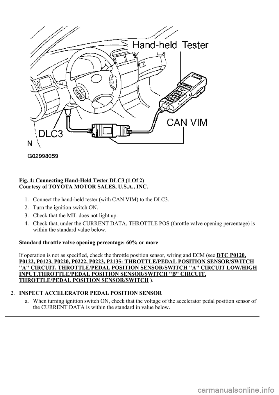
Fig. 4: Connecting Hand-Held Tester DLC3 (1 Of 2)
Courtesy of TOYOTA MOTOR SALES, U.S.A., INC.
1. Connect the hand-held tester (with CAN VIM) to the DLC3.
2. Turn the ignition switch ON.
3. Check that the MIL does not light up.
4. Check that, under the CURRENT DATA, THROTTLE POS (throttle valve opening percentage) is
within the standard value below.
Standard throttle valve opening percentage: 60% or more
If operation is not as specified, check the throttle position sensor, wiring and ECM (see DTC P0120,
P0122, P0123, P0220, P0222, P0223, P2135: THROTTLE/PEDAL POSITION SENSOR/SWITCH
"A" CIRCUIT, THROTTLE/PEDAL POSITION SENSOR/SWITCH "A" CIRCUIT LOW/HIGH
INPUT,THROTTLE/PEDAL POSITION SENSOR/SWITCH "B" CIRCUIT,
THROTTLE/PEDAL POSITION SENSOR/SWITCH ).
2.INSPECT ACCELERATOR PEDAL POSITION SENSOR
a. When turning ignition switch ON, check that the voltage of the accelerator pedal position sensor of
<0057004b004800030026003800350035002800310037000300270024003700240003004c00560003005a004c0057004b004c005100030057004b00480003005600570044005100470044005500470003004c0051000300590044004f005800480003004500
48004f0052005a00110003[
Page 3021 of 4500
Fig. 37: Taping Screwdriver Tip Before Use
Courtesy of TOYOTA MOTOR SALES, U.S.A., INC.
g. Adjust the striker position by slightly loosening the striker mounting screws and hitting the striker
with a plastic-faced hammer.
h. Tighten the striker mounting screws after the adjustment.
Torque: 23 N.m (235 kgf.cm, 17 ft.lbf)
i. Connect the negative (-) terminal cable to the battery.
j. Initialize both systems (see INITIALIZATION
).
k. Inspect the SRS warning lamp (see DIAGNOSIS SYSTEM
).
Page 3077 of 4500
Fig. 90: Removing Cover
Courtesy of TOYOTA MOTOR SALES, U.S.A., INC.
k. Adjust the striker position by slightly loosening the striker mounting screws and hitting the striker
with a plastic-faced hammer.
l. Tighten the striker mounting screws after the adjustment.
Torque: 23 N.m (235 kgf.cm, 17 ft.lbf)
m. Connect the negative (-) terminal cable to the battery.
n. Initialize both systems (see INITIALIZATION
).
o. Inspect the SRS warning lamp (see DIAGNOSIS SYSTEM
).
Page 3079 of 4500
Fig. 92: Removing Rear Door Inside Handle Bezel LH
Courtesy of TOYOTA MOTOR SALES, U.S.A., INC.
2.REMOVE REAR DOOR ARMREST BASE PANEL UPPER
a. Using a screwdriver, pry the armrest panel assembly.
HINT:
Tape the screwdriver tip before use.
b. Using a screwdriver, disengage the 2 claws and remove the window control switch from the
armrest panel assembly.
HINT:
Tape the screwdriver tip before use.
c. Disconnect the connector and ash receptacle light, and remove the armrest base panel assembly.
d. Remove the 2 screws and armrest base panel lower from the armrest base panel upper.