Page 2520 of 4500

OK: Go To Next Step.
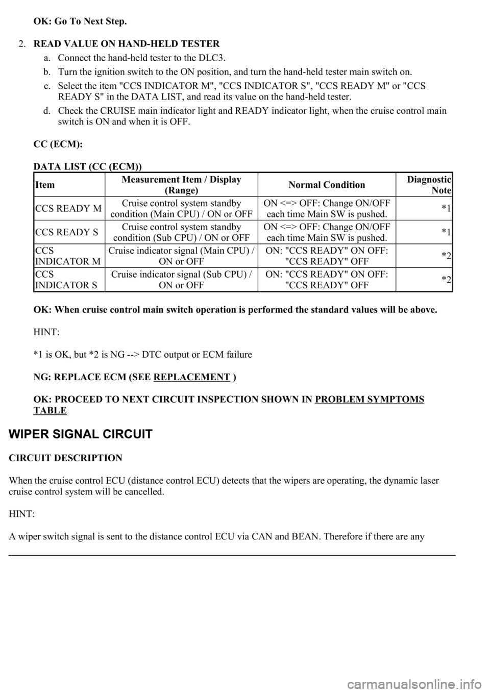
2.READ VALUE ON HAND-HELD TESTER
a. Connect the hand-held tester to the DLC3.
b. Turn the ignition switch to the ON position, and turn the hand-held tester main switch on.
c. Select the item "CCS INDICATOR M", "CCS INDICATOR S", "CCS READY M" or "CCS
READY S" in the DATA LIST, and read its value on the hand-held tester.
d. Check the CRUISE main indicator light and READY indicator light, when the cruise control main
switch is ON and when it is OFF.
CC (ECM):
DATA LIST (CC (ECM))
OK: When cruise control main switch operation is performed the standard values will be above.
HINT:
*1 is OK, but *2 is NG --> DTC output or ECM failure
NG: REPLACE ECM (SEE REPLACEMENT
)
OK: PROCEED TO NEXT CIRCUIT INSPECTION SHOWN IN PROBLEM SYMPTOMS
TABLE
CIRCUIT DESCRIPTION
When the cruise control ECU (distance control ECU) detects that the wipers are operating, the dynamic laser
cruise control system will be cancelled.
HINT:
A wiper switch si
gnal is sent to the distance control ECU via CAN and BEAN. Therefore if there are any
ItemMeasurement Item / Display
(Range)Normal ConditionDiagnostic
Note
CCS READY MCruise control system standby
condition (Main CPU) / ON or OFFON <=> OFF: Change ON/OFF
each time Main SW is pushed.*1
CCS READY SCruise control system standby
condition (Sub CPU) / ON or OFFON <=> OFF: Change ON/OFF
each time Main SW is pushed.*1
CCS
INDICATOR MCruise indicator signal (Main CPU) /
ON or OFFON: "CCS READY" ON OFF:
"CCS READY" OFF*2
CCS
INDICATOR SCruise indicator signal (Sub CPU) /
ON or OFFON: "CCS READY" ON OFF:
"CCS READY" OFF*2
Page 2522 of 4500
Courtesy of TOYOTA MOTOR SALES, U.S.A., INC.
HINT:
When a particular warning light stays blinking, a ground short in the wiring of terminal TC of the DLC3 or an
internal ground short in the relevant ECU is suspected.
INSPECTION PROCEDURE
1.CHECK HARNESS AND CONNECTOR (TC of DLC3 - ECM)
a. Disconnect the E2 connector from the ECM.
b. Measure the resistance according to the value(s) in the table below.
Standard:
ECM CONNECTOR TERMINALS RESISTANCE SPECIFICATION
Fig. 85: Identifying DLC3 Connector (TC) Terminals
Courtesy of TOYOTA MOTOR SALES, U.S.A., INC.
Tester connectionConditionSpecified condition
TC (E2-3) - TC (D1 - 13)AlwaysBelow 1 ohms
Page 2526 of 4500

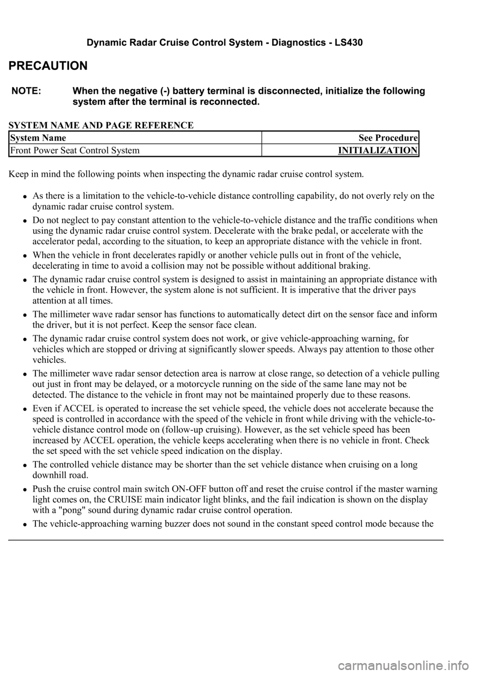
SYSTEM NAME AND PAGE REFERENCE
Keep in mind the following points when inspecting the dynamic radar cruise control system.
As there is a limitation to the vehicle-to-vehicle distance controlling capability, do not overly rely on the
dynamic radar cruise control system.
Do not neglect to pay constant attention to the vehicle-to-vehicle distance and the traffic conditions when
using the dynamic radar cruise control system. Decelerate with the brake pedal, or accelerate with the
accelerator pedal, according to the situation, to keep an appropriate distance with the vehicle in front.
When the vehicle in front decelerates rapidly or another vehicle pulls out in front of the vehicle,
decelerating in time to avoid a collision may not be possible without additional braking.
The dynamic radar cruise control system is designed to assist in maintaining an appropriate distance with
the vehicle in front. However, the system alone is not sufficient. It is imperative that the driver pays
attention at all times.
The millimeter wave radar sensor has functions to automatically detect dirt on the sensor face and inform
the driver, but it is not perfect. Keep the sensor face clean.
The dynamic radar cruise control system does not work, or give vehicle-approaching warning, for
vehicles which are stopped or driving at significantly slower speeds. Always pay attention to those other
vehicles.
The millimeter wave radar sensor detection area is narrow at close range, so detection of a vehicle pulling
out just in front may be delayed, or a motorcycle running on the side of the same lane may not be
detected. The distance to the vehicle in front may not be maintained properly due to these reasons.
Even if ACCEL is operated to increase the set vehicle speed, the vehicle does not accelerate because the
speed is controlled in accordance with the speed of the vehicle in front while driving with the vehicle-to-
vehicle distance control mode on (follow-up cruising). However, as the set vehicle speed has been
increased by ACCEL operation, the vehicle keeps accelerating when there is no vehicle in front. Check
the set speed with the set vehicle speed indication on the display.
The controlled vehicle distance may be shorter than the set vehicle distance when cruising on a long
downhill road.
Push the cruise control main switch ON-OFF button off and reset the cruise control if the master warning
light comes on, the CRUISE main indicator light blinks, and the fail indication is shown on the display
with a "pong" sound during dynamic radar cruise control operation.
The vehicle-approaching warning buzzer does not sound in the constant speed control mode because the
System NameSee Procedure
Front Power Seat Control SystemINITIALIZATION
Page 2558 of 4500
Fig. 27: Signal Waveform Graph (Waveform 2)
Courtesy of TOYOTA MOTOR SALES, U.S.A., INC.
1.DIAGNOSIS FUNCTION
a. The diagnosis function makes the master warning light and the multi-information display come on,
and the CRUISE main indicator light blinks as shown in the illustration. When a malfunction
occurs in the dynamic radar cruise control system, the DTCs are stored in the ECM.
Page 2559 of 4500
Fig. 28: Identifying Master Warning Light And CRUISE Main Indicator Light
Courtesy of TOYOTA MOTOR SALES, U.S.A., INC.
Page 2560 of 4500
Fig. 29: Identifying Blinking Pattern Of CRUISE Main Indicator Light
Courtesy of TOYOTA MOTOR SALES, U.S.A., INC.
2.DESCRIPTION
a. The ECM controls the dynamic radar cruise control system of the vehicle. The data and DTCs
relating to the dynamic radar cruise control system can be read from the DLC3 of the vehicle. If
either DTC or CRUISE OK is not displayed in the multi-information display on the combination
meter when checking for DTCs, there may be a problem with the combination meter or the CAN
communication and multiplex communication system.
Use the hand-held tester to check and solve the problem.
3.CHECK THE DLC3
a. The vehicle's ECM uses ISO 9141-2 for communication. The terminal arrangement of the DLC3
complies with SAE J1962 and matches the ISO 9141-2 format.
Page 2562 of 4500

tester to the DLC3, turned the ignition switch to the ON position and operated the tester, there is a
problem on either the vehicle side or the tool side.
If communication is normal when the tool is connected to another vehicle, inspect the DLC3 on the
original vehicle.
If communication is still impossible when the tool is connected to another vehicle, the problem is
probably in the tool itself, so consult the Service Department listed in the tool's instruction manual.
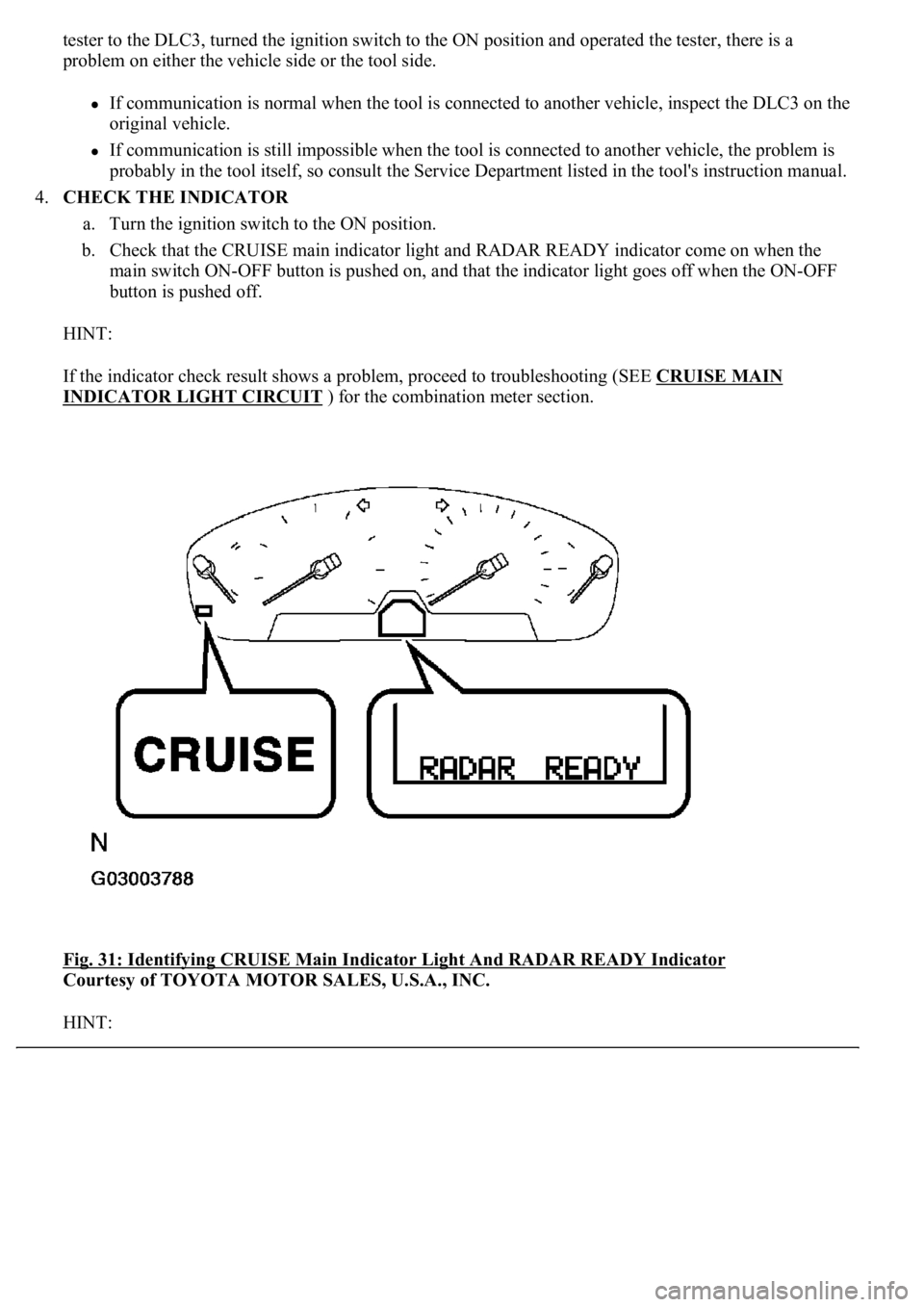
4.CHECK THE INDICATOR
a. Turn the ignition switch to the ON position.
b. Check that the CRUISE main indicator light and RADAR READY indicator come on when the
main switch ON-OFF button is pushed on, and that the indicator light goes off when the ON-OFF
button is pushed off.
HINT:
If the indicator check result shows a problem, proceed to troubleshooting (SEE CRUISE MAIN
INDICATOR LIGHT CIRCUIT ) for the combination meter section.
<0029004c004a0011000300160014001d0003002c0047004800510057004c0049005c004c0051004a0003002600350038002c00360028000300300044004c00510003002c00510047004c004600440057005200550003002f004c004a004b00570003002400
51004700030035002400270024003500030035002800240027[Y Indicator
Courtesy of TOYOTA MOTOR SALES, U.S.A., INC.
HINT:
Page 2563 of 4500
If a malfunction occurs in the vehicle speed sensors, the stop lamp switch, or other related parts during
cruise control driving, the ECU actuates AUTO CANCEL of the cruise control and blinks the CRUISE
main indicator light. This indicator light informs the driver of the malfunction. At the same time, the
malfunction is stored as a diagnostic trouble code.
Fig. 32: Identifying Blinking Pattern Of CRUISE Main Indicator Light
Courtesy of TOYOTA MOTOR SALES, U.S.A., INC.
1.DTC CHECK
a. Connect the hand-held tester to the DLC3.
b. Turn the ignition switch to the ON position.
c. Read the DTCs by following the prompts on the tester screen.
2.DTC CLEAR
a. Connect the hand-held tester to the DLC3.
b. Turn the ignition switch to the ON position.
c. Clear the DTCs following the prompts on the tester screen.
HINT:
Refer to the han
d-held tester operators manual for further details.