Page 1079 of 4500
REPLACEMENT
1.REMOVE ENGINE ROOM SIDE COVER
2.SEPARATE ENGINE ROOM NO.3 R/B
a. Remove the bolt and separate the engine room No.3 R/B.
3.REMOVE FRONT WHEEL
4.REMOVE FRONT FENDER LINER
Remove the front fender outside moulding, front fender splash shield and front fender liner LH.
5.DRAIN BRAKE FLUID
a. Draw out fluid with syringe.
6.REMOVE ABS & TRACTION ACTUATOR ASSY WITH BRACKET
a. Using SST, disconnect the 6 brake tubes from the ABS & TRACTION actuator assy with bracket.
SST 09751-36011
Fig. 110: Disconnecting Brake Tubes From ABS & TRACTION ACTUATOR ASSY WITH
Page 1084 of 4500
18.INSTALL FRONT WHEEL
19.CONNECT ENGINE ROOM NO.3 R/B
a. Install the engine room No.3 R/B and bolt.
20.INSTALL ENGINE ROOM SIDE COVER
21.PERFORM YAWRATE SENSOR ZERO POINT CALIBRATION AND TEST MODE
COMPONENTS
Page 1223 of 4500

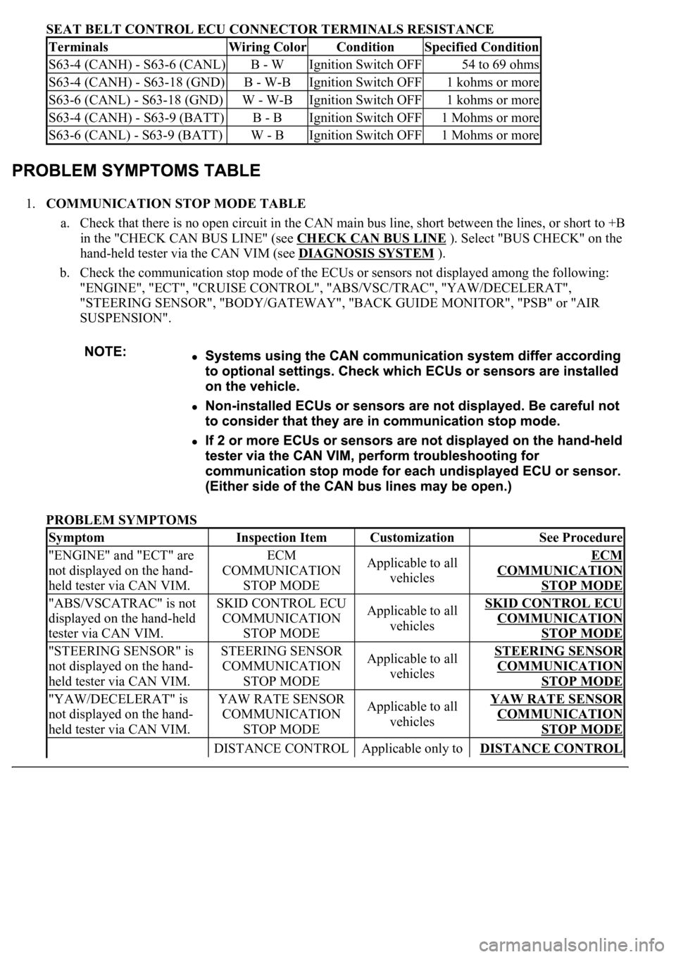
SEAT BELT CONTROL ECU CONNECTOR TERMINALS RESISTANCE
1.COMMUNICATION STOP MODE TABLE
a. Check that there is no open circuit in the CAN main bus line, short between the lines, or short to +B
in the "CHECK CAN BUS LINE" (see CHECK CAN BUS LINE
). Select "BUS CHECK" on the
hand-held tester via the CAN VIM (see DIAGNOSIS SYSTEM
).
b. Check the communication stop mode of the ECUs or sensors not displayed among the following:
"ENGINE", "ECT", "CRUISE CONTROL", "ABS/VSC/TRAC", "YAW/DECELERAT",
"STEERING SENSOR", "BODY/GATEWAY", "BACK GUIDE MONITOR", "PSB" or "AIR
SUSPENSION".
PROBLEM SYMPTOMS
TerminalsWiring ColorConditionSpecified Condition
S63-4 (CANH) - S63-6 (CANL)B - WIgnition Switch OFF54 to 69 ohms
S63-4 (CANH) - S63-18 (GND)B - W-BIgnition Switch OFF1 kohms or more
S63-6 (CANL) - S63-18 (GND)W - W-BIgnition Switch OFF1 kohms or more
S63-4 (CANH) - S63-9 (BATT)B - BIgnition Switch OFF1 Mohms or more
S63-6 (CANL) - S63-9 (BATT)W - BIgnition Switch OFF1 Mohms or more
SymptomInspection ItemCustomizationSee Procedure
"ENGINE" and "ECT" are
not displayed on the hand-
held tester via CAN VIM.ECM
COMMUNICATION
STOP MODEApplicable to all
vehiclesECM
COMMUNICATION
STOP MODE
"ABS/VSCATRAC" is not
displayed on the hand-held
tester via CAN VIM.SKID CONTROL ECU
COMMUNICATION
STOP MODEApplicable to all
vehiclesSKID CONTROL ECU
COMMUNICATION
STOP MODE
"STEERING SENSOR" is
not displayed on the hand-
held tester via CAN VIM.STEERING SENSOR
COMMUNICATION
STOP MODEApplicable to all
vehiclesSTEERING SENSOR
COMMUNICATION
STOP MODE
"YAW/DECELERAT" is
not displayed on the hand-
held tester via CAN VIM.YAW RATE SENSOR
COMMUNICATION
STOP MODEApplicable to all
vehiclesYAW RATE SENSOR
COMMUNICATION
STOP MODE
DISTANCE CONTROL Applicable only to DISTANCE CONTROL
Page 1232 of 4500

HINT:
Rx: Reception from each ECU (sensor).
Tx: Transmission to each ECU (sensor).
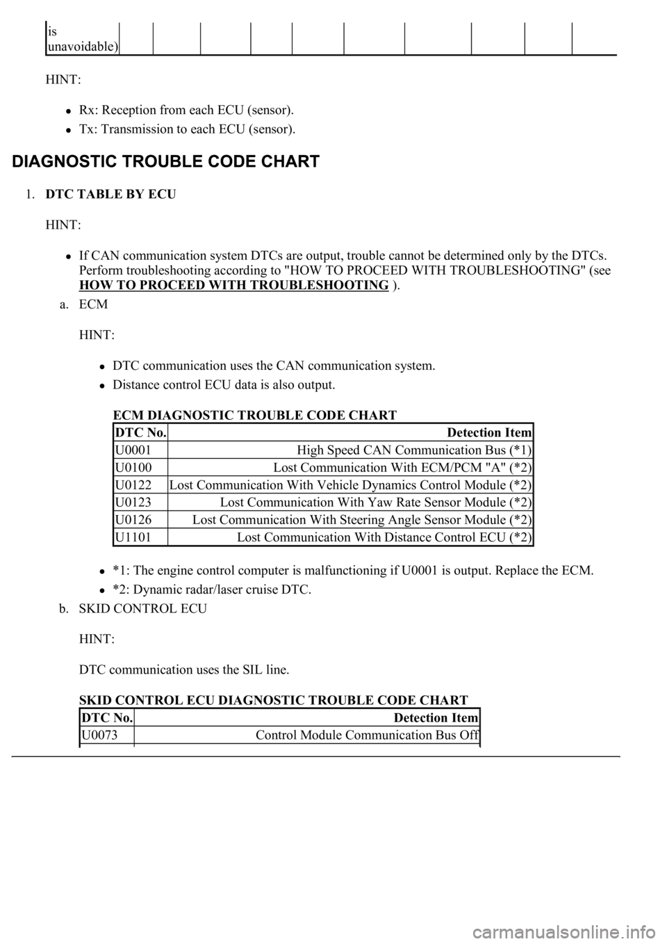
1.DTC TABLE BY ECU
HINT:
If CAN communication system DTCs are output, trouble cannot be determined only by the DTCs.
Perform troubleshooting according to "HOW TO PROCEED WITH TROUBLESHOOTING" (see
HOW TO PROCEED WITH TROUBLESHOOTING
).
a. ECM
HINT:
DTC communication uses the CAN communication system.
Distance control ECU data is also output.
ECM DIAGNOSTIC TROUBLE CODE CHART
*1: The engine control computer is malfunctioning if U0001 is output. Replace the ECM.
*2: Dynamic radar/laser cruise DTC.
b. SKID CONTROL ECU
HINT:
DTC communication uses the SIL line.
SKID CONTROL ECU DIAGNOSTIC TROUBLE CODE CHART
is
unavoidable)
DTC No.Detection Item
U0001High Speed CAN Communication Bus (*1)
U0100Lost Communication With ECM/PCM "A" (*2)
U0122Lost Communication With Vehicle Dynamics Control Module (*2)
U0123Lost Communication With Yaw Rate Sensor Module (*2)
U0126Lost Communication With Steering Angle Sensor Module (*2)
U1101Lost Communication With Distance Control ECU (*2)
DTC No.Detection Item
U0073Control Module Communication Bus Off
Page 1503 of 4500

a. This system uses ultrasonic sensors to detect any obstacles at the corners, the front or the rear of the
vehicle. The system then informs the driver of the distance between the sensors and the obstacles,
as well as their positions by displaying them on the multi-information display in the combination
meter and by sounding a buzzer. This information also appears on the multi-display on the models
equipped with a LEXUS navigation system.
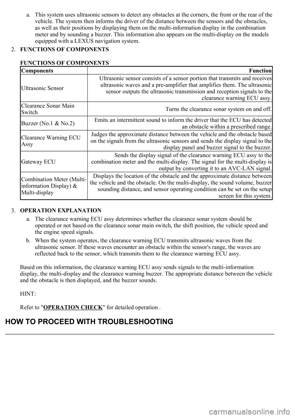
2.FUNCTIONS OF COMPONENTS
FUNCTIONS OF COMPONENTS
3.OPERATION EXPLANATION
a. The clearance warning ECU assy determines whether the clearance sonar system should be
operated or not based on the clearance sonar main switch, the shift position, the vehicle speed and
the engine speed signals.
b. When the system operates, the clearance warning ECU transmits ultrasonic waves from the
ultrasonic sensor. If these waves encounter an obstacle within the sensor's range, the waves are
reflected back to the sensor, which transmits them to the clearance warning ECU assy.
Based on this information, the clearance warning ECU assy sends signals to the multi-information
display, the multi-display and the clearance warning buzzer. The appropriate distance between the vehicle
and the obstacle is then displayed, and the buzzer sounds.
HINT:
Refer to "OPERATION CHECK
" for detailed operation .
ComponentsFunction
Ultrasonic Sensor
Ultrasonic sensor consists of a sensor portion that transmits and receives
ultrasonic waves and a pre-amplifier that amplifies them. The ultrasonic
sensor outputs the ultrasonic transmission and reception signals to the
clearance warning ECU assy.
Clearance Sonar Main
SwitchTurns the clearance sonar system on and off.
Buzzer (No.1 & No.2)Emits an intermittent sound to inform the driver that the ECU has detected
an obstacle within a prescribed range.
Clearance Warning ECU
AssyJudges the approximate distance between the vehicle and the obstacle based
on the signals from the ultrasonic sensors and sends the display signal to the
display panel and buzzer signal to the buzzer.
Gateway ECU
Sends the display signal of the clearance warning ECU assy to the
combination meter and the multi-display. The signal for the multi-display is
output by converting it to an AVC-LAN signal.
Combination Meter (Multi-
information Display) &
Multi-displayDisplays the location of the obstacle and the approximate distance between
the vehicle and the obstacle. On the multi-display, the sound volume, buzzer
sounding distance, and sensor operating condition can be set on the setup
screen for this system.
Page 1509 of 4500
Front sonar:
CLEARANCE SONAR MAIN SWITCH
HINT:
Because sound waves are used for detection range measurement, the detection range may change
sli
ghtly due to the peripheral temperature.
Ignition
switchClearance sonar
main switchShift positionVehicle speedEngine speed
ONONIn any position
except P and R10 km/h (6
mph) or lessN position: 1,500 RPM or less
Except N position: 2,500 RPM or
less
Page 1511 of 4500
HINT:
Clearance sonar display does not appear on the multi-display if the shift lever is moved to the
R position.
Because sound waves are used for detection range measurement, the detection range may
chan
ge slightly due to the peripheral temperature.
Ignition
switchClearance sonar main
switchShift
positionVehicle speedEngine speed
ONONR position10 km/h (6 mph) or
less2,500 RPM or
less
Page 1513 of 4500
Rear clearance sonar:
CLEARANCE SONAR MAIN SWITCH
HINT:
Clearance sonar display does not appear on the multi-display if the shift lever is moved to the
R position.
Because sound waves are used for detection range measurement, the detection range may
chan
ge slightly due to the peripheral temperature.
Ignition
switchClearance sonar
main switchShift positionVehicle speedEngine speed
ONONIn any position
except P and R10 km/h (6
mph) or lessN position 1,500 RPM or less
Except N position 2,500 RPM or
less
Ignition
switchClearance sonar main
switchShift
positionVehicle speedEngine speed
ONONR position10 km/h (6 mph) or
less2,500 RPM or
less