Page 824 of 4500
4. The D shift indicator comes on again when the fluid temperature reaches 46°C (115°F) and
blinks when it exceeds 56°C (130°F).
5. Allow the engine to idle until the fluid temperature reaches 46°C (115°F).
HINT:
The fluid temperature should be less than 30°C (86°F) before check the fluid temperature.
6.FLUID LEVEL CHECK
a. Remove the overflow plug with the engine idling.
b. Check that the fluid comes out of the overflow tube.
If fluid does not come out, proceed to step 7
If fluid comes out, wait until the over-flow slows to a trickle and proceed to step 8.
Fig. 6: Removing Overflow Plug
Courtesy of TOYOTA MOTOR SALES, U.S.A., INC.
Page 825 of 4500

7.TRANSMISSION
a. Install the overflow plug.
b. Stop the engine.
c. Remove the refill plug.
d. Add 0.4 liters (0.42 US qts, 0.35 Imp. qts) of fluid.
e. Allow the engine to idle and wait for 10 seconds.
f. Proceed to next step.
8.COMPLETE
a. Install the overflow plug with a new gasket.
b. Stop the engine.
c. Install the refill plug with a new gasket.
d. Install the transmission case cover with the two bolts.
Torque:
20 N.m (204 kgf.cm, 15 ft.lbf) for overflow plug
39 N.m (400 kgf.cm, 53 ft.lbf) for refill plug
REPLACEMENT
1.DISCONNECT BATTERY NEGATIVE TERMINAL
2.REMOVE INSTRUMENT PANEL UNDER COVER SUB-ASSY NO.2 (SEE REPLACEMENT
)
3.REMOVE INSTRUMENT PANEL GARNISH SUB-ASSY LH (SEE REPLACEMENT
)
4.REMOVE INSTRUMENT PANEL FINISH PANEL (SEE REPLACEMENT
)
5.REMOVE INSTRUMENT PANEL UNDER COVER SUB-ASSY NO.1 (SEE REPLACEMENT
)
6.REMOVE SWITCH BRACE HOLE COVER (SEE REPLACEMENT
)
7.REMOVE INSTRUMENT PANEL SAFETY PAD SUB-ASSY NO.1 (SEE REPLACEMENT
)
8.REMOVE INSTRUMENT PANEL CUP HOLDER ASSY (SEE REPLACEMENT
)
9.REMOVE CONSOLE UPPER REAR PANEL SUB-ASSY (SEE REPLACEMENT
)
10.REMOVE CONSOLE BOX CARPET (SEE REPLACEMENT
)
11.REMOVE REAR CONSOLE ARMREST ASSY (SEE REPLACEMENT
)
12.REMOVE INSTRUMENT PANEL FINISH PANEL LOWER CENTER (SEE REPLACEMENT
)
13.REMOVE INSTRUMENT CLUSTER FINISH PANEL SUB-ASSY CENTER (SEE
REPLACEMENT
)
14.REMOVE CONSOLE PANEL SUB-ASSY UPPER (SEE REPLACEMENT
)
15.REMOVE CONSOLE BOX (SEE REPLACEMENT
)
16.SEPARATE OXYGEN SENSOR (SEE REPLACEMENT
)
Page 826 of 4500
17.REMOVE FRONT FLOOR BRACE CENTER (SEE REPLACEMENT )
18.REMOVE EXHAUST PIPE ASSY (SEE REPLACEMENT
)
19.REMOVE FRONT FLOOR HEAT INSULATOR NO.1 (SEE REPLACEMENT
)
20.REMOVE PROPELLER W/CENTER BEARING SHAFT ASSY (SEE OVERHAUL
)
SST 09922-10010
21.SEPARATE FLOOR SHIFT GEAR SHIFTING ROD SUB-ASSY
a. Remove the nut and separate the floor shift gear shifting rod.
Fig. 7: Removing Nut And Separating Floor Shift Gear Shifting Rod
Courtesy of TOYOTA MOTOR SALES, U.S.A., INC.
22.SUPPORT AUTOMATIC TRANSMISSION ASSY
a. Support the automatic transmission assy with a transmission jack.
23.SEPARATE ENGINE REAR MOUNTING MEMBER
a. Remove the 4 bolts and separate the engine rear mounting member.
Page 827 of 4500
Fig. 8: Removing 4 Bolts And Separating Engine Rear Mounting Member
Courtesy of TOYOTA MOTOR SALES, U.S.A., INC.
24.REMOVE TRANSMISSION CONTROL SHAFT LEVER RH
a. Remove the nut and transmission control shaft lever RH.
Page 836 of 4500
Fig. 17: Installing Transmission Control Shaft Lever RH With Nut
Courtesy of TOYOTA MOTOR SALES, U.S.A., INC.
b. Connect the park/neutral position switch connector.
28.INSTALL ENGINE REAR MOUNTING MEMBER
a. Install the engine rear mounting member with the 4 bolts.
Torque: 26 N.m (270 kgf.cm, 20 ft.lbf)
Page 837 of 4500
Fig. 18: Installing Engine Rear Mounting Member With 4 Bolts
Courtesy of TOYOTA MOTOR SALES, U.S.A., INC.
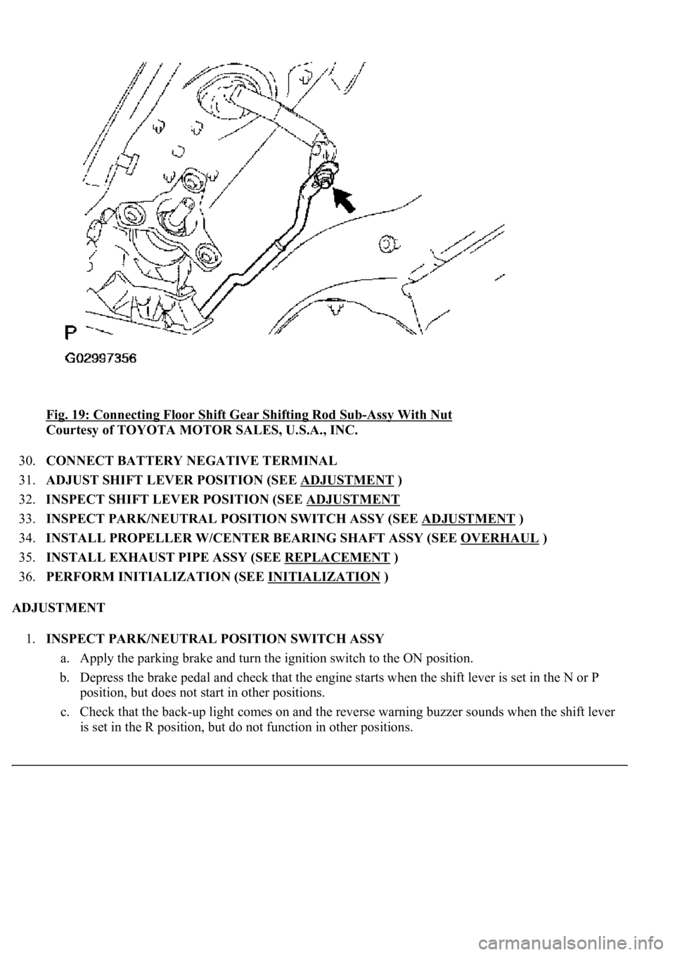
29.CONNECT FLOOR SHIFT GEAR SHIFTING ROD SUB-ASSY
a. Connect the floor shift gear shifting rod sub-assy with the nut.
Torque: 13 N.m (130 kgf.cm, 9 ft.lbf)
Page 838 of 4500

<0029004c004a001100030014001c001d00030026005200510051004800460057004c0051004a00030029004f00520052005500030036004b004c004900570003002a00480044005500030036004b004c00490057004c0051004a0003003500520047000300
3600580045[-Assy With Nut
Courtesy of TOYOTA MOTOR SALES, U.S.A., INC.
30.CONNECT BATTERY NEGATIVE TERMINAL
31.ADJUST SHIFT LEVER POSITION (SEE ADJUSTMENT
)
32.INSPECT SHIFT LEVER POSITION (SEE ADJUSTMENT
33.INSPECT PARK/NEUTRAL POSITION SWITCH ASSY (SEE ADJUSTMENT
)
34.INSTALL PROPELLER W/CENTER BEARING SHAFT ASSY (SEE OVERHAUL
)
35.INSTALL EXHAUST PIPE ASSY (SEE REPLACEMENT
)
36.PERFORM INITIALIZATION (SEE INITIALIZATION
)
ADJUSTMENT
1.INSPECT PARK/NEUTRAL POSITION SWITCH ASSY
a. Apply the parking brake and turn the ignition switch to the ON position.
b. Depress the brake pedal and check that the engine starts when the shift lever is set in the N or P
position, but does not start in other positions.
c. Check that the back-up light comes on and the reverse warning buzzer sounds when the shift lever
is set in the R position, but do not function in other positions.
Page 844 of 4500
Fig. 25: Identifying Automatic Transmission Assy Components
Courtesy of TOYOTA MOTOR SALES, U.S.A., INC.
REPLACEMENT
1.DISCONNECT BATTERY NEGATIVE TERMINAL
2.REMOVE ENGINE UNDER COVER NO.1