Page 1514 of 4500
Fig. 8: Identifying Clearance Sonar Display
Courtesy of TOYOTA MOTOR SALES, U.S.A., INC.
2.INITIAL CHECK FUNCTION CHECK
a. Turn the ignition switch to the ON position.
b. Drive the engine at 2,500 RPM or less with the shift lever in any position except N, or at 1,500
RPM or less with the shift lever in the N position.
Page 1596 of 4500

HINT:
*1: For vehicles with a rear seat heater system
*2: For vehicles with a rear seat climate control system
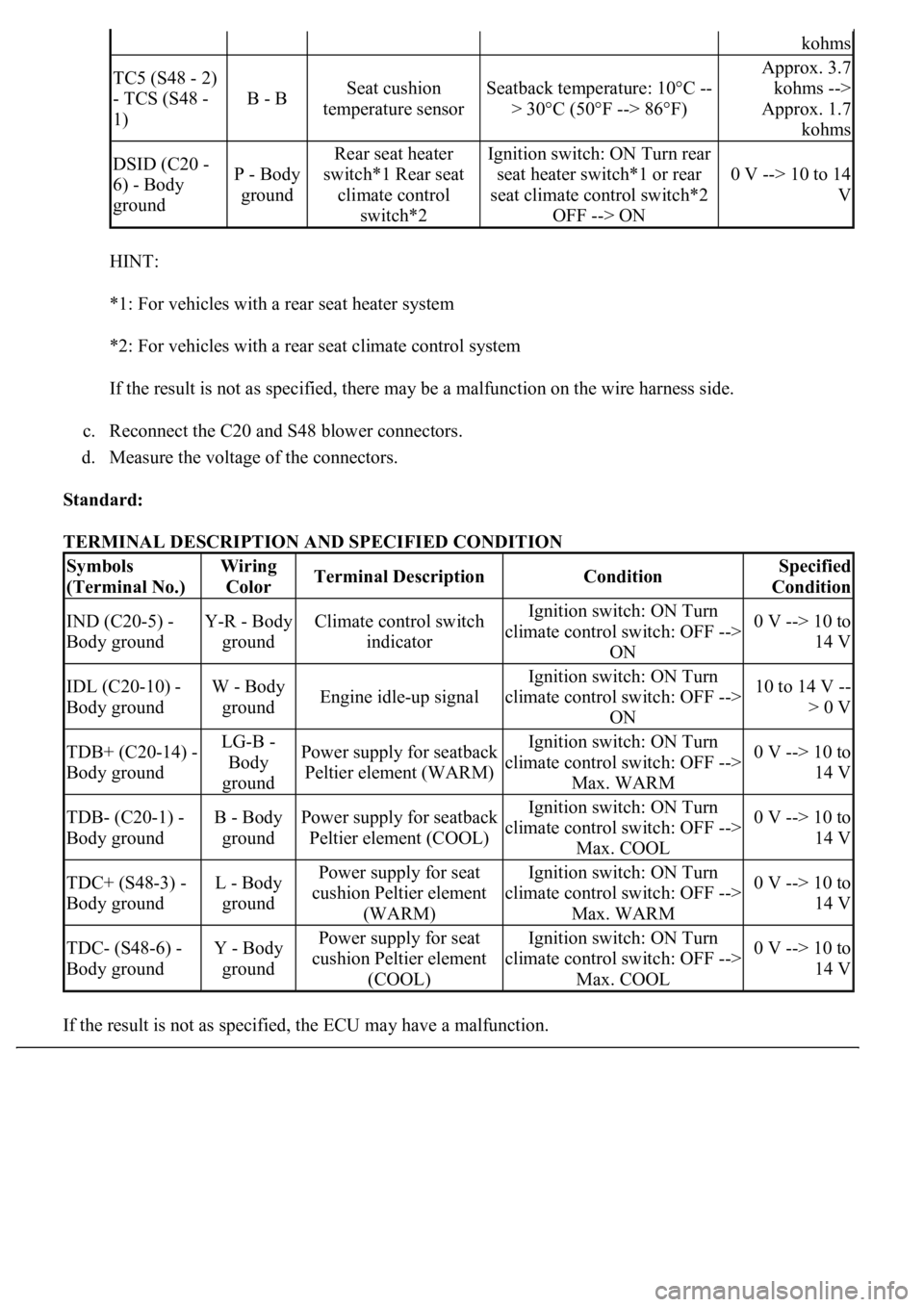
If the result is not as specified, there may be a malfunction on the wire harness side.
c. Reconnect the C20 and S48 blower connectors.
d. Measure the voltage of the connectors.
Standard:
TERMINAL DESCRIPTION AND SPECIFIED CONDITION
If the result is not as specified, the ECU ma
y have a malfunction.
kohms
TC5 (S48 - 2)
- TCS (S48 -
1)
B - BSeat cushion
temperature sensorSeatback temperature: 10°C --
> 30°C (50°F --> 86°F)
Approx. 3.7
kohms -->
Approx. 1.7
kohms
DSID (C20 -
6) - Body
groundP - Body
ground
Rear seat heater
switch*1 Rear seat
climate control
switch*2Ignition switch: ON Turn rear
seat heater switch*1 or rear
seat climate control switch*2
OFF --> ON
0 V --> 10 to 14
V
Symbols
(Terminal No.)Wiring
ColorTerminal DescriptionConditionSpecified
Condition
IND (C20-5) -
Body groundY-R - Body
groundClimate control switch
indicatorIgnition switch: ON Turn
climate control switch: OFF -->
ON0 V --> 10 to
14 V
IDL (C20-10) -
Body groundW - Body
groundEngine idle-up signal
Ignition switch: ON Turn
climate control switch: OFF -->
ON10 to 14 V --
> 0 V
TDB+ (C20-14) -
Body groundLG-B -
Body
groundPower supply for seatback
Peltier element (WARM)Ignition switch: ON Turn
climate control switch: OFF -->
Max. WARM0 V --> 10 to
14 V
TDB- (C20-1) -
Body groundB - Body
groundPower supply for seatback
Peltier element (COOL)Ignition switch: ON Turn
climate control switch: OFF -->
Max. COOL0 V --> 10 to
14 V
TDC+ (S48-3) -
Body groundL - Body
groundPower supply for seat
cushion Peltier element
(WARM)Ignition switch: ON Turn
climate control switch: OFF -->
Max. WARM0 V --> 10 to
14 V
TDC- (S48-6) -
Body groundY - Body
groundPower supply for seat
cushion Peltier element
(COOL)Ignition switch: ON Turn
climate control switch: OFF -->
Max. COOL0 V --> 10 to
14 V
Page 1601 of 4500

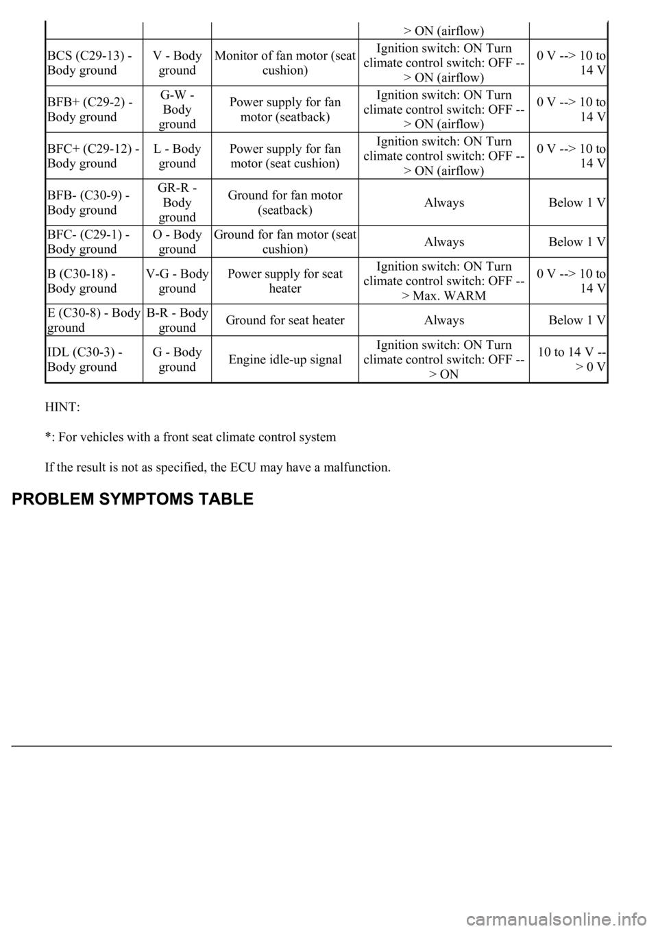
HINT:
*: For vehicles with a front seat climate control system
If the result is not as specified, the ECU may have a malfunction.
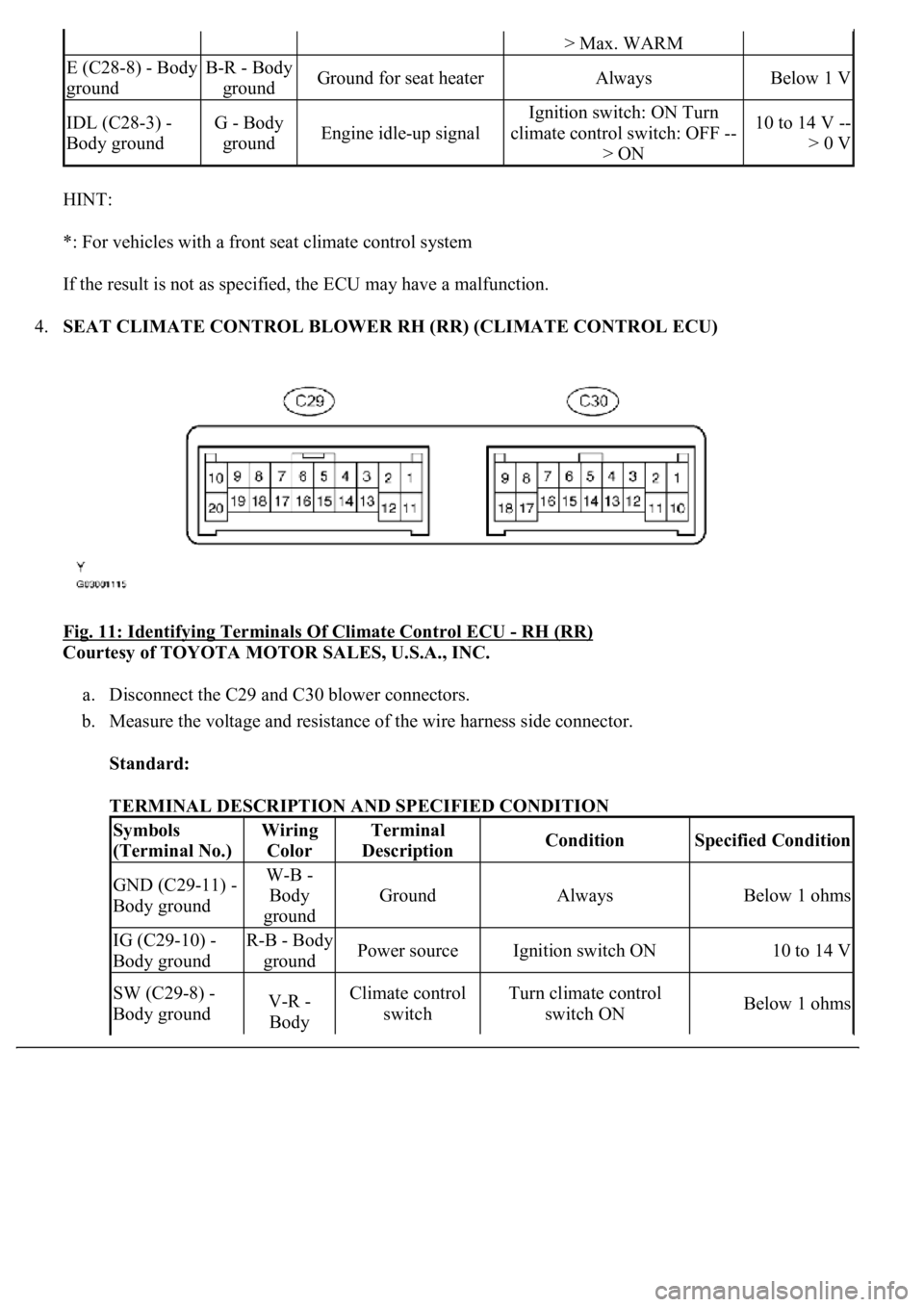
4.SEAT CLIMATE CONTROL BLOWER RH (RR) (CLIMATE CONTROL ECU)
Fig. 11: Identifying Terminals Of Climate Control ECU
- RH (RR)
Courtesy of TOYOTA MOTOR SALES, U.S.A., INC.
a. Disconnect the C29 and C30 blower connectors.
b. Measure the voltage and resistance of the wire harness side connector.
Standard:
TERMINAL DESCRIPTION AND SPECIFIED CONDITION
> Max. WARM
E (C28-8) - Body
groundB-R - Body
groundGround for seat heaterAlwaysBelow 1 V
IDL (C28-3) -
Body groundG - Body
groundEngine idle-up signal
Ignition switch: ON Turn
climate control switch: OFF --
> ON10 to 14 V --
> 0 V
Symbols
(Terminal No.)Wiring
ColorTerminal
DescriptionConditionSpecified Condition
GND (C29-11) -
Body groundW-B -
Body
ground
GroundAlwaysBelow 1 ohms
IG (C29-10) -
Body groundR-B - Body
groundPower sourceIgnition switch ON10 to 14 V
SW (C29-8) -
Body groundV-R -
Body Climate control
switchTurn climate control
switch ONBelow 1 ohms
Page 1603 of 4500

HINT:
*: For vehicles with a front seat climate control system
If the result is not as specified, the ECU may have a malfunction.
> ON (airflow)
BCS (C29-13) -
Body groundV - Body
groundMonitor of fan motor (seat
cushion)Ignition switch: ON Turn
climate control switch: OFF --
> ON (airflow)0 V --> 10 to
14 V
BFB+ (C29-2) -
Body groundG-W -
Body
groundPower supply for fan
motor (seatback)Ignition switch: ON Turn
climate control switch: OFF --
> ON (airflow)0 V --> 10 to
14 V
BFC+ (C29-12) -
Body groundL - Body
groundPower supply for fan
motor (seat cushion)Ignition switch: ON Turn
climate control switch: OFF --
> ON (airflow)0 V --> 10 to
14 V
BFB- (C30-9) -
Body groundGR-R -
Body
groundGround for fan motor
(seatback)AlwaysBelow 1 V
BFC- (C29-1) -
Body groundO - Body
groundGround for fan motor (seat
cushion)AlwaysBelow 1 V
B (C30-18) -
Body groundV-G - Body
groundPower supply for seat
heaterIgnition switch: ON Turn
climate control switch: OFF --
> Max. WARM0 V --> 10 to
14 V
E (C30-8) - Body
groundB-R - Body
groundGround for seat heaterAlwaysBelow 1 V
IDL (C30-3) -
Body groundG - Body
groundEngine idle-up signal
Ignition switch: ON Turn
climate control switch: OFF --
> ON10 to 14 V --
> 0 V
Page 1743 of 4500
Fig. 10: Communication Signal Reference Chart BEAN (Column)
Courtesy of TOYOTA MOTOR SALES, U.S.A., INC.
AVC-LAN:
Fig. 11: Communication Signal Reference Chart (AVC
-LAN)
Courtesy of TOYOTA MOTOR SALES, U.S.A., INC.
1.METER GAUGE AND WARNING/INDICATOR
GAUGE:
GAUGE DETAIL
WARNING/INDICATOR:
ItemDetail
SpeedometerBased on a signal received from the wheel speed sensor, the skid control ECU
calculates vehicle speed and transmits the data to the meter (Direct line).
TachometerECM transmits engine speed to the meter display (Direct line).
Water Temperature
GaugeDisplays water temperature receiving a signal from the ECM (BEAN).
Fuel GaugeReceives the fuel sender gauge signal from the luggage room J/B ECU (BEAN).
Page 1762 of 4500
Fig. 26: Identifying Terminals Of ECU (Combination Meter Assy)
Courtesy of TOYOTA MOTOR SALES, U.S.A., INC.
COMBINATION METER ASSY CONNECTOR TERMINALS REFERENCE
Symbols
(Terminals No.)Wiring
ColorTerminal DescriptionConditionSpecified
Condition
IG + (C12-1) -
Body groundY - Body
groundIgnition switch signal
(ON)Ignition switch OFF -->
ONBelow 1 V --> 10
to 14 V
MPX + (C12-2) -
Body groundGR-B -
Body groundMultiplex
communication signal--
MPX- (C12-3) -
Body groundGR-B -
Body groundMultiplex
communication signal--
S (C12-4) - Body
groundB-Y - Body
groundTachometer signalEngine runningPulse generation
(See waveform 1)
CHECK (C12-5) -
Body groundY-R - Body
groundCHECK ENGINE
signalCHECK ENGINE warning
light ON --> OFFBelow 1 V --> 10
to 14 V
TEMS (C12-6) -
Body groundY - Body
groundTEMS SPORT signalTEMS SPORT indicator
light ON --> OFFBelow 1 V --> 10
to 14 V
A/B (C12-7) - V-R (W) - ODO/TRIP signalIgnition switch ON,
ODO/TRIP switch ON -->
Below 1 V --> 4.5
Page 1764 of 4500
Fig. 27: Identifying Waveform 1
Courtesy of TOYOTA MOTOR SALES, U.S.A., INC.
Waveform 1 (Reference):
WAVEFORM 1 (REFERENCE)
ItemContents
Tool setting5V/DIV, 10 ms/DIV
Vehicle conditionEngine idle speed
Page 1779 of 4500

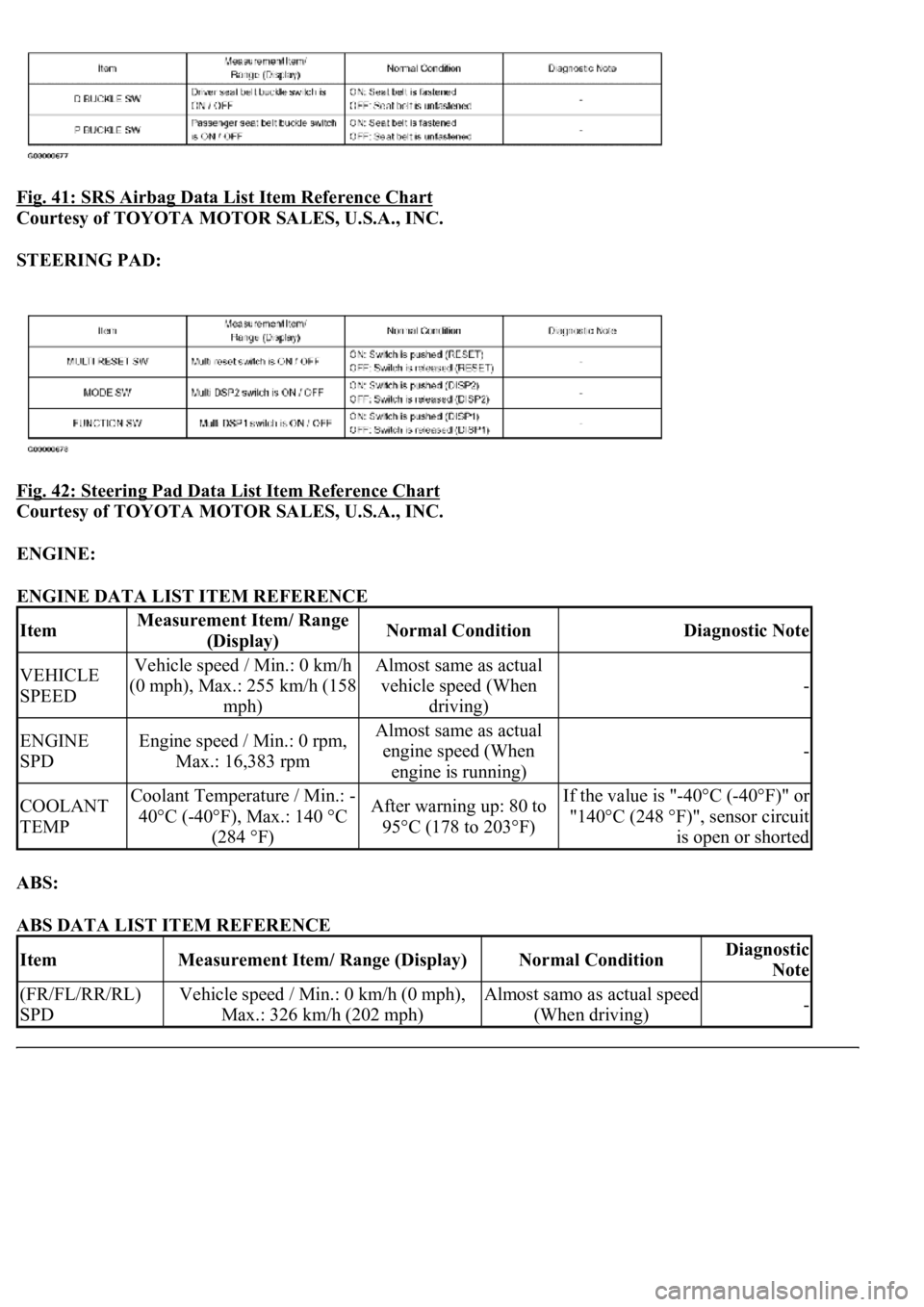
Fig. 41: SRS Airbag Data List Item Reference Chart
Courtesy of TOYOTA MOTOR SALES, U.S.A., INC.
STEERING PAD:
Fig. 42: Steering Pad Data List Item Reference Chart
Courtesy of TOYOTA MOTOR SALES, U.S.A., INC.
ENGINE:
ENGINE DATA LIST ITEM REFERENCE
ABS:
ABS DATA LIST ITEM REFERENCE
ItemMeasurement Item/ Range
(Display)Normal ConditionDiagnostic Note
VEHICLE
SPEEDVehicle speed / Min.: 0 km/h
(0 mph), Max.: 255 km/h (158
mph)Almost same as actual
vehicle speed (When
driving)
-
ENGINE
SPDEngine speed / Min.: 0 rpm,
Max.: 16,383 rpmAlmost same as actual
engine speed (When
engine is running)
-
COOLANT
TEMPCoolant Temperature / Min.: -
40°C (-40°F), Max.: 140 °C
(284 °F)After warning up: 80 to
95°C (178 to 203°F)If the value is "-40°C (-40°F)" or
"140°C (248 °F)", sensor circuit
is open or shorted
ItemMeasurement Item/ Range (Display)Normal ConditionDiagnostic
Note
(FR/FL/RR/RL)
SPDVehicle speed / Min.: 0 km/h (0 mph),
Max.: 326 km/h (202 mph)Almost samo as actual speed
(When driving)-