Page 1780 of 4500

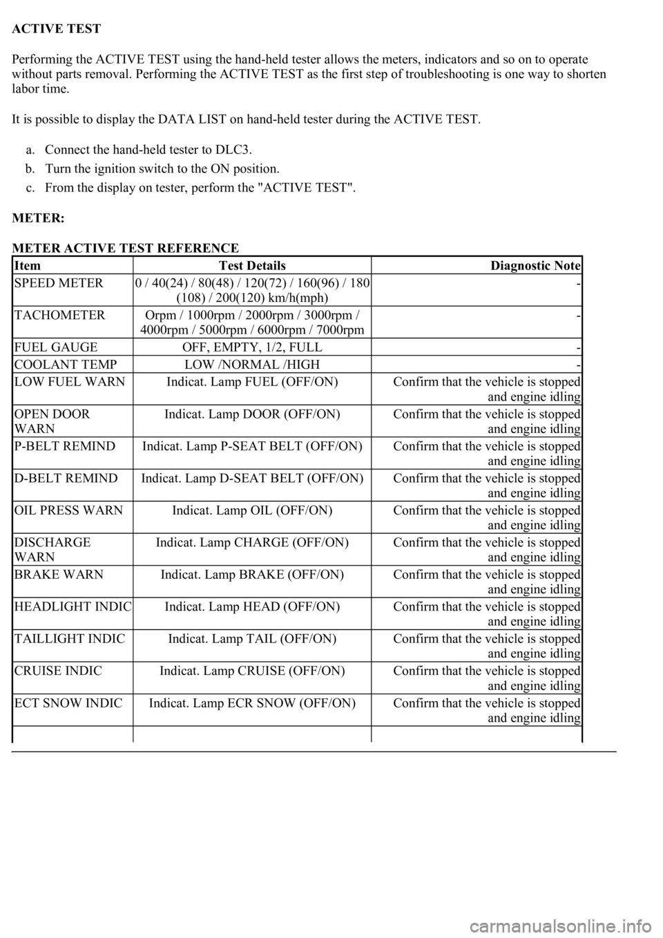
ACTIVE TEST
Performing the ACTIVE TEST using the hand-held tester allows the meters, indicators and so on to operate
without parts removal. Performing the ACTIVE TEST as the first step of troubleshooting is one way to shorten
labor time.
It is possible to display the DATA LIST on hand-held tester during the ACTIVE TEST.
a. Connect the hand-held tester to DLC3.
b. Turn the ignition switch to the ON position.
c. From the display on tester, perform the "ACTIVE TEST".
METER:
METER ACTIVE TEST REFERENCE
ItemTest DetailsDiagnostic Note
SPEED METER0 / 40(24) / 80(48) / 120(72) / 160(96) / 180
(108) / 200(120) km/h(mph)-
TACHOMETEROrpm / 1000rpm / 2000rpm / 3000rpm /
4000rpm / 5000rpm / 6000rpm / 7000rpm-
FUEL GAUGEOFF, EMPTY, 1/2, FULL-
COOLANT TEMPLOW /NORMAL /HIGH-
LOW FUEL WARNIndicat. Lamp FUEL (OFF/ON)Confirm that the vehicle is stopped
and engine idling
OPEN DOOR
WARNIndicat. Lamp DOOR (OFF/ON)Confirm that the vehicle is stopped
and engine idling
P-BELT REMINDIndicat. Lamp P-SEAT BELT (OFF/ON)Confirm that the vehicle is stopped
and engine idling
D-BELT REMINDIndicat. Lamp D-SEAT BELT (OFF/ON)Confirm that the vehicle is stopped
and engine idling
OIL PRESS WARNIndicat. Lamp OIL (OFF/ON)Confirm that the vehicle is stopped
and engine idling
DISCHARGE
WARNIndicat. Lamp CHARGE (OFF/ON)Confirm that the vehicle is stopped
and engine idling
BRAKE WARNIndicat. Lamp BRAKE (OFF/ON)Confirm that the vehicle is stopped
and engine idling
HEADLIGHT INDICIndicat. Lamp HEAD (OFF/ON)Confirm that the vehicle is stopped
and engine idling
TAILLIGHT INDICIndicat. Lamp TAIL (OFF/ON)Confirm that the vehicle is stopped
and engine idling
CRUISE INDICIndicat. Lamp CRUISE (OFF/ON)Confirm that the vehicle is stopped
and engine idling
ECT SNOW INDICIndicat. Lamp ECR SNOW (OFF/ON)Confirm that the vehicle is stopped
and engine idling
Page 1781 of 4500

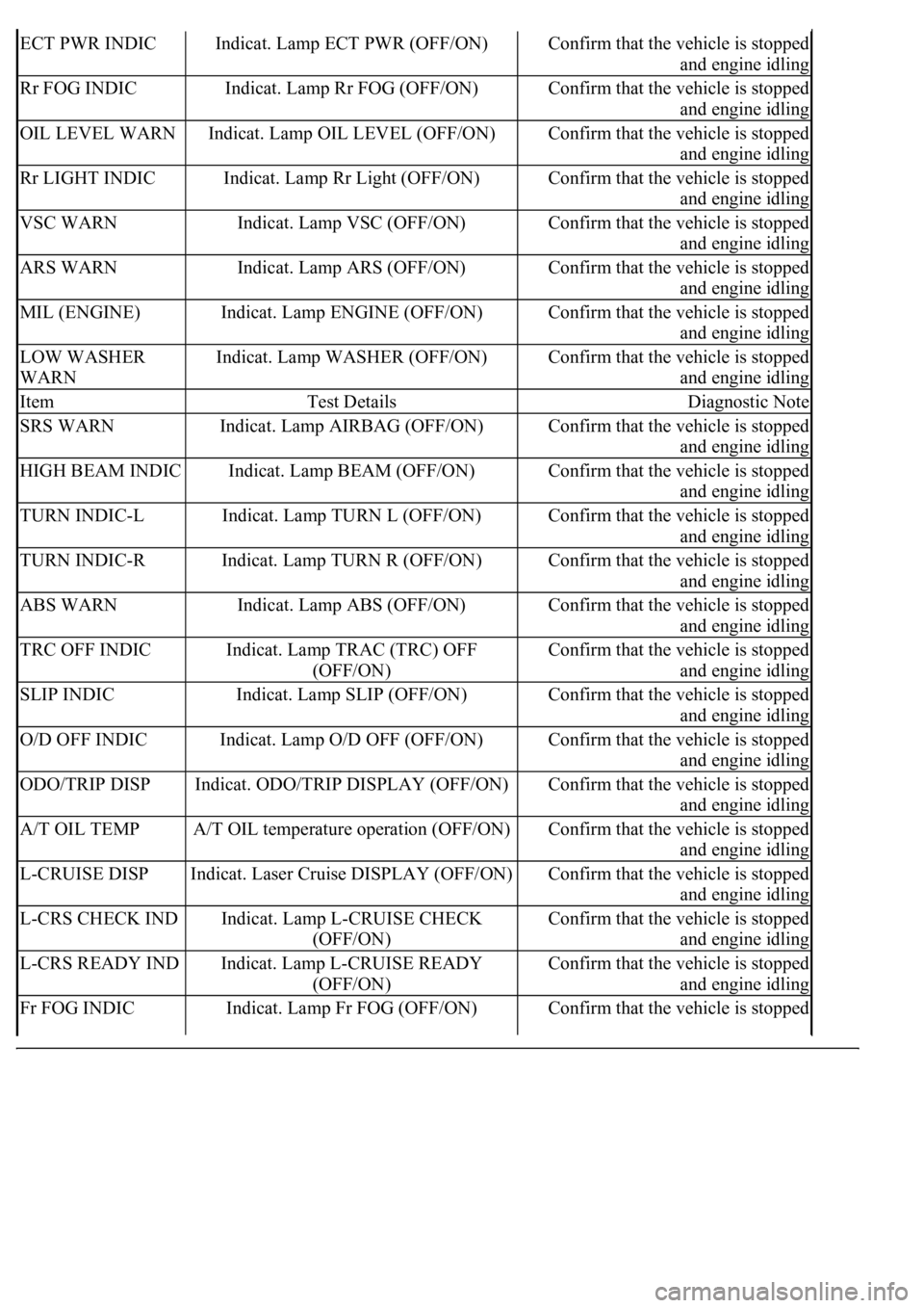
ECT PWR INDICIndicat. Lamp ECT PWR (OFF/ON)Confirm that the vehicle is stopped
and engine idling
Rr FOG INDICIndicat. Lamp Rr FOG (OFF/ON)Confirm that the vehicle is stopped
and engine idling
OIL LEVEL WARNIndicat. Lamp OIL LEVEL (OFF/ON)Confirm that the vehicle is stopped
and engine idling
Rr LIGHT INDICIndicat. Lamp Rr Light (OFF/ON)Confirm that the vehicle is stopped
and engine idling
VSC WARNIndicat. Lamp VSC (OFF/ON)Confirm that the vehicle is stopped
and engine idling
ARS WARNIndicat. Lamp ARS (OFF/ON)Confirm that the vehicle is stopped
and engine idling
MIL (ENGINE)Indicat. Lamp ENGINE (OFF/ON)Confirm that the vehicle is stopped
and engine idling
LOW WASHER
WARNIndicat. Lamp WASHER (OFF/ON)Confirm that the vehicle is stopped
and engine idling
ItemTest DetailsDiagnostic Note
SRS WARNIndicat. Lamp AIRBAG (OFF/ON)Confirm that the vehicle is stopped
and engine idling
HIGH BEAM INDICIndicat. Lamp BEAM (OFF/ON)Confirm that the vehicle is stopped
and engine idling
TURN INDIC-LIndicat. Lamp TURN L (OFF/ON)Confirm that the vehicle is stopped
and engine idling
TURN INDIC-RIndicat. Lamp TURN R (OFF/ON)Confirm that the vehicle is stopped
and engine idling
ABS WARNIndicat. Lamp ABS (OFF/ON)Confirm that the vehicle is stopped
and engine idling
TRC OFF INDICIndicat. Lamp TRAC (TRC) OFF
(OFF/ON)Confirm that the vehicle is stopped
and engine idling
SLIP INDICIndicat. Lamp SLIP (OFF/ON)Confirm that the vehicle is stopped
and engine idling
O/D OFF INDICIndicat. Lamp O/D OFF (OFF/ON)Confirm that the vehicle is stopped
and engine idling
ODO/TRIP DISPIndicat. ODO/TRIP DISPLAY (OFF/ON)Confirm that the vehicle is stopped
and engine idling
A/T OIL TEMPA/T OIL temperature operation (OFF/ON)Confirm that the vehicle is stopped
and engine idling
L-CRUISE DISPIndicat. Laser Cruise DISPLAY (OFF/ON)Confirm that the vehicle is stopped
and engine idling
L-CRS CHECK INDIndicat. Lamp L-CRUISE CHECK
(OFF/ON)Confirm that the vehicle is stopped
and engine idling
L-CRS READY INDIndicat. Lamp L-CRUISE READY
(OFF/ON)Confirm that the vehicle is stopped
and engine idling
Fr FOG INDICIndicat. Lamp Fr FOG (OFF/ON)Confirm that the vehicle is stopped
Page 1782 of 4500

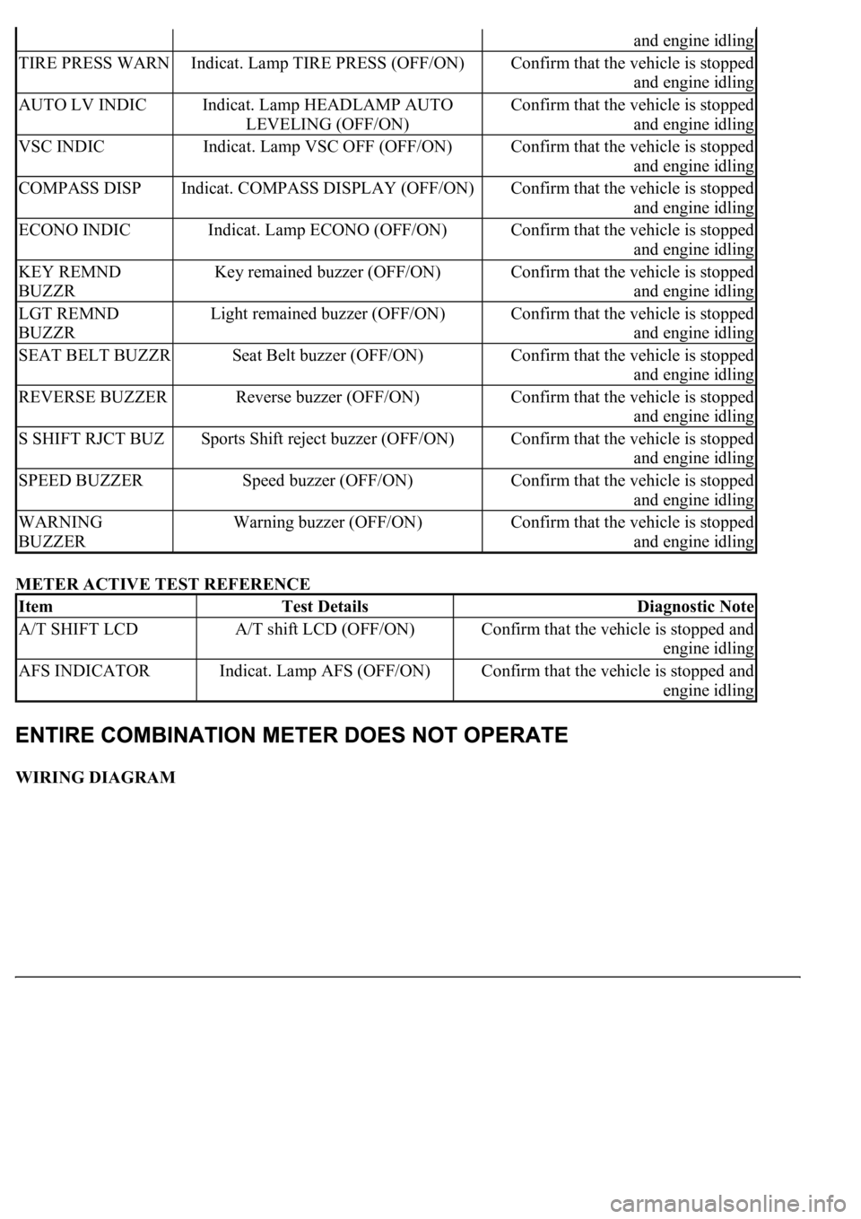
METER ACTIVE TEST REFERENCE
WIRING DIAGRAM
and engine idling
TIRE PRESS WARNIndicat. Lamp TIRE PRESS (OFF/ON)Confirm that the vehicle is stopped
and engine idling
AUTO LV INDICIndicat. Lamp HEADLAMP AUTO
LEVELING (OFF/ON)Confirm that the vehicle is stopped
and engine idling
VSC INDICIndicat. Lamp VSC OFF (OFF/ON)Confirm that the vehicle is stopped
and engine idling
COMPASS DISPIndicat. COMPASS DISPLAY (OFF/ON)Confirm that the vehicle is stopped
and engine idling
ECONO INDICIndicat. Lamp ECONO (OFF/ON)Confirm that the vehicle is stopped
and engine idling
KEY REMND
BUZZRKey remained buzzer (OFF/ON)Confirm that the vehicle is stopped
and engine idling
LGT REMND
BUZZRLight remained buzzer (OFF/ON)Confirm that the vehicle is stopped
and engine idling
SEAT BELT BUZZRSeat Belt buzzer (OFF/ON)Confirm that the vehicle is stopped
and engine idling
REVERSE BUZZERReverse buzzer (OFF/ON)Confirm that the vehicle is stopped
and engine idling
S SHIFT RJCT BUZSports Shift reject buzzer (OFF/ON)Confirm that the vehicle is stopped
and engine idling
SPEED BUZZERSpeed buzzer (OFF/ON)Confirm that the vehicle is stopped
and engine idling
WARNING
BUZZERWarning buzzer (OFF/ON)Confirm that the vehicle is stopped
and engine idling
ItemTest DetailsDiagnostic Note
A/T SHIFT LCDA/T shift LCD (OFF/ON)Confirm that the vehicle is stopped and
engine idling
AFS INDICATORIndicat. Lamp AFS (OFF/ON)Confirm that the vehicle is stopped and
engine idling
Page 1792 of 4500
WIRING DIAGRAM
Fig. 50: Tachometer Wiring Diagram
Courtesy of TOYOTA MOTOR SALES, U.S.A., INC.
INSPECTION PROCEDURE
1.PERFORM ACTIVE TEST BY HAND-HELD TESTER
a. Operate the hand-held tester according to the steps on the display and select the "ACTIVE TEST".
METER:
TACHO METER ACTIVE TEST REFERENCE
OK:
Needle indication is normal.
NG: REPLACE COMBINATION METER ASSY (SEE OVERHAUL
)
OK: GO TO NEXT STEP
2.READ VALUE OF HAND-HELD TESTER (ENGINE SPEED SIGNAL)
a. Operate the han
d-held tester according to the steps on the display and select the "DATA LIST".
ItemTest DetailsDiagnostic
Note
TACHOMETEROrpm / 1000rpm / 2000rpm / 3000rpm / 4000rpm / 5000rpm /
6000rpm / 7000rpm-
Page 1793 of 4500

METER:
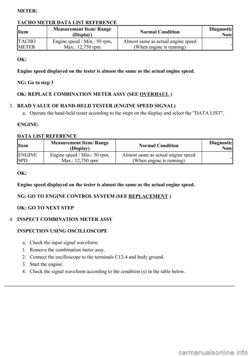
TACHO METER DATA LIST REFERENCE
OK:
Engine speed displayed on the tester is almost the same as the actual engine speed.
NG: Go to step 3
OK: REPLACE COMBINATION METER ASSY (SEE OVERHAUL
)
3.READ VALUE OF HAND-HELD TESTER (ENGINE SPEED SIGNAL)
a. Operate the hand-held tester according to the steps on the display and select the "DATA LIST".
ENGINE:
DATA LIST REFERENCE
OK:
Engine speed displayed on the tester is almost the same as the actual engine speed.
NG: GO TO ENGINE CONTROL SYSTEM (SEE REPLACEMENT
)
OK: GO TO NEXT STEP
4.INSPECT COMBINATION METER ASSY
INSPECTION USING OSCILLOSCOPE
a. Check the input signal waveform.
1. Remove the combination meter assy.
2. Connect the oscilloscope to the terminals C12-4 and body ground.
3. Start the engine.
4. Check the si
gnal waveform according to the condition (s) in the table below.
ItemMeasurement Item/ Range
(Display)Normal ConditionDiagnostic
Note
TACHO
METEREngine speed / Min.: 50 rpm,
Max.: 12,750 rpmAlmost same as actual engine speed
(When engine is running)-
ItemMeasurement Item/ Range
(Display)Normal ConditionDiagnostic
Note
ENGINE
SPDEngine speed / Min.: 50 rpm,
Max.: 12,750 rpmAlmost same as actual engine speed
(When engine is running)-
Page 1794 of 4500
SIGNAL WAVEFORM CONDITION
OK:
As shown in the illustration
Fig. 51: Identifying Terminals C12
-4
Courtesy of TOYOTA MOTOR SALES, U.S.A., INC.
ItemCondition
Tool setting5 V/DIV, 10 ms/DIV
Vehicle conditionEngine idle speed
Page 1798 of 4500
Courtesy of TOYOTA MOTOR SALES, U.S.A., INC.
OK: GO TO ENGINE CONTROL SYSTEM (SEE REPLACEMENT
)
WIRING DIAGRAM
Fig. 55: Fuel Receiver Gauge Wiring Diagram
Courtesy of TOYOTA MOTOR SALES, U.S.A., INC.
INSPECTION PROCEDURE
1.PERFORM ACTIVE TEST BY HAND-HELD TESTER
a. Operate the hand-held tester according to the steps on the display and select the "ACTIVE TEST".
METER:
METER ACTIVE TEST REFERENCE
OK:
Needle indication is normal.
NG: REPLACE COMBINATION METER ASSY (SEE OVERHAUL
)
ItemTest DetailsDiagnostic Note
FUEL GAUGEOFF, EMPTY, 1/2, FULL-
Page 1810 of 4500
Fig. 63: Identifying Fuel Sender Gauge Assy And Luggage Room Junction Block Assy Connector
Terminals
Courtesy of TOYOTA MOTOR SALES, U.S.A., INC.
NG: REPAIR OR REPLACE HARNESS OR CONNECTOR
OK: REPLACE LUGGAGE ROOM JUNCTION BLOCK ASSY
WIRING DIAGRAM
Fig. 64: Water Temperature Receiver Gauge Wiring Diagram
Courtesy of TOYOTA MOTOR SALES, U.S.A., INC.
INSPECTION PROCEDURE
HINT:
If there is an open or short in the engine coolant temperature sensor circuit, the ECM outputs DTCs. Perform
troubleshooting with the "SFI System 10-2".
1.PERFORM ACTIVE TEST BY HAND-HELD TESTER
a. Operate the hand-held tester according to the steps on the display and select the "ACTIVE TEST".
METER:
ACTIVE TEST REFERENCE