Page 412 of 4500
Fig. 156: Identifying Blower Motor Circuit Description
Courtesy of TOYOTA MOTOR SALES, U.S.A., INC.
WIRING DIAGRAM
Fig. 157: Blower Motor Circuit
Courtesy of TOYOTA MOTOR SALES, U.S.A., INC.
INSPECTION PROCEDURE
1.READ VALUE ON HAND-HELD TESTER
a. Connect the hand-held tester to the DLC3.
b. Turn the ignition switch to the ON position and push the hand-held tester main switch on.
c. Select the item below in the DATA LIST, and read the displa
y on the hand-held tester.
Page 413 of 4500

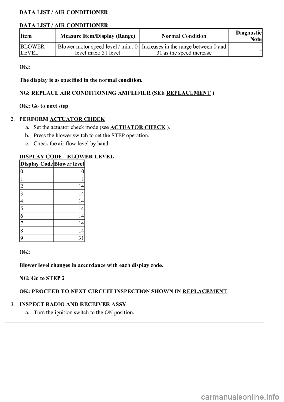
DATA LIST / AIR CONDITIONER:
DATA LIST / AIR CONDITIONER
OK:
The display is as specified in the normal condition.
NG: REPLACE AIR CONDITIONING AMPLIFIER (SEE REPLACEMENT
)
OK: Go to next step
2.PERFORM ACTUATOR CHECK
a. Set the actuator check mode (see ACTUATOR CHECK
).
b. Press the blower switch to set the STEP operation.
c. Check the air flow level by hand.
DISPLAY CODE - BLOWER LEVEL
OK:
<0025004f0052005a004800550003004f004800590048004f00030046004b00440051004a004800560003004c0051000300440046004600520055004700440051004600480003005a004c0057004b0003004800440046004b00030047004c00560053004f00
44005c000300460052004700480011[
NG: Go to STEP 2
OK: PROCEED TO NEXT CIRCUIT INSPECTION SHOWN IN REPLACEMENT
3.INSPECT RADIO AND RECEIVER ASSY
a. Turn the ignition switch to the ON position.
ItemMeasure Item/Display (Range)Normal ConditionDiagnostic
Note
BLOWER
LEVELBlower motor speed level / min.: 0
level max.: 31 levelIncreases in the range between 0 and
31 as the speed increase-
Display CodeBlower level
00
11
214
314
414
514
614
714
814
931
Page 414 of 4500
b. Turn the radio and receiver assy on.
c. Set the radio channels and register them.
d. Turn the ignition switch off.
e. Turn the ignition switch to the ON position.
f. Turn the radio and receiver assy on.
g. Check if the registered memory is deleted or not.
OK:
The registered memory is not deleted.
NG: REPAIR OR REPLACE HARNESS OR CONNECTOR (DRIVER SIDE J/B - BATTERY)
OK: Go to next step
4.INSPECT FUSE (HEATER)
a. Remove the HEATER fuse from the FL block.
b. Measure the resistance according to the value (s) in the table below.
Standard:
FUSE (HEATER) RESISTANCE
NG: CHECK FOR SHORT IN ALL HARNESSES AND COMPONENTS CONNECTED TO
FAILURE FUSE
Tester itemConditionSpecified condition
HEATER fuseAlwaysBelow 1 ohms
Page 419 of 4500
NG: REPAIR OR REPLACE HARNESS OR CONNECTOR
OK: Go to next step
8.INSPECT BLOWER MOTOR
a. Remove the blower motor.
b. Connect positive (+) lead to terminal 2 of the blower motor connector and negative (-) lead to
terminal 1.
OK: Blower motor operates smoothly.
Fig. 162: Inspecting Blower Motor
Courtesy of TOYOTA MOTOR SALES, U.S.A., INC.
NG: REPLACE BLOWER MOTOR
OK: Go to next step
9.INSPECT AIR CONDITIONING AMPLIFIER (BLW - BODY GROUND)
a. Remove the A/C amplifier with connectors still connected.
b. Turn the ignition switch to the ON position.
Page 421 of 4500
Fig. 164: Identifying Waveform Between Terminal BLW (A11-5) Of A/C Amplifier And Body
Ground
Courtesy of TOYOTA MOTOR SALES, U.S.A., INC.
OK: PROCEED TO NEXT CIRCUIT INSPECTION SHOWN IN PROBLEM SYMPTOMS
TABLE
CIRCUIT DESCRIPTION
This is the backup power source for the rear A/C amplifier. Power is supplied even when the ignition switch is
off and is used for memory, etc.
WIRING DIAGRAM
Page 424 of 4500
Fig. 167: Inspecting Rear Air Conditioning Amplifier (R-B - Body Ground)
Courtesy of TOYOTA MOTOR SALES, U.S.A., INC.
OK: PROCEED TO NEXT CIRCUIT INSPECTION SHOWN IN PROBLEM SYMPTOMS
TABLE
CIRCUIT DESCRIPTION
The main power source is supplied to the A/C amplifier when the ignition switch is turned to the ON position.
The power source supplied is used for operating the A/C amplifier and servomotor, etc.
WIRING DIAGRAM
Page 426 of 4500
FUSE (RR A/C) RESISTANCE
NG: CHECK FOR SHORT IN ALL HARNESS AND COMPONENTS CONNECTED TO
FAILURE FUSE (RR A/C FUSE)
OK: Go to next step
2.INSPECT REAR AIR CONDITIONING AMPLIFIER (IG - GND)
a. Remove the A/C amplifier assy with connectors still connected.
b. Turn the ignition switch to the ON position.
c. Measure the voltage according to the value (s) in the table below.
Standard:
REAR AIR CONDITIONING AMPLIFIER (IG - GND) VOLTAGE
NG: PROCEED TO NEXT CIRCUIT INSPECTION SHOWN IN PROBLEM SYMPTOMS
TABLE
Tester itemConditionSpecified condition
RR A/C fuseAlwaysBelow 1 ohms
Tester connectionConditionSpecified condition
A46-10 (IG) -A46-6 (GND)Ignition switch OFF --> ONBelow 1 V --> 10 to 14 V
Page 427 of 4500
Fig. 169: Inspecting Rear Air Conditioning Amplifier (IG - GND)
Courtesy of TOYOTA MOTOR SALES, U.S.A., INC.
3.CHECK HARNESS AND CONNECTOR (REAR AIR CONDITIONING AMPLIFIER -
BATTERY) (SEE ELECTRONIC CIRCUIT INSPECTION PROCEDURE
)
a. Disconnect the rear A/C amplifier connector.
b. Measure the voltage according to the value (s) in the table below.
Standard:
REAR AIR CONDITIONING AMPLIFIER -BATTERY VOLTAGE
NG: REPAIR OR REPLACE HARNESS OR CONNECTOR
Tester connectionConditionSpecified condition
A46-10 (IG) - Body groundIgnition switch OFF --> ONBelow 1.0V --> 10 to 14 V