Page 129 of 173
 2003 Owners Manual IN CASE OF EMERGENCY
IN CASE OF EMERGENCY IN CASE OF EMERGENCY
IN CASE OF EMERGENCY
IN CASE OF EMERGENCY
4-14 The following points should be observed:
1. Both batteries must be 12V. The capacity
(Ah)")
IN CASE OF EMERGENCY
IN CASE OF EMERGENCY IN CASE OF EMERGENCY
IN CASE OF EMERGENCY
IN CASE OF EMERGENCY
4-14 The following points should be observed:
1. Both batteries must be 12V. The capacity
(Ah) of the battery supplying current should not be significantly below that of the dis-charged battery.
2. Use only heavy-duty jumper cables.
3. A discharged battery can freeze. A frozen battery must be thawed out before connect- ing the jumper cables.
4. There should be no contact between the two vehicles; otherwise current may flow whenthe positive terminal is connected.
5. The discharged battery must be correctly connected to the vehicle electrical system.
6. Run the engine of the vehicle supplying current.
7. Connect the jumper cables as follows:
(1) Connect one end of one jumper cable to the positive terminal of the flat battery, and the other end to the positive terminal of thebooster battery.
(2) Connect one end of the other jumper cable to the negative terminal of the booster bat-tery, and the other end to the engine blockof the vehicle with the flat battery at the pointfarthest from the battery.
GS40330A
E110A02P-GAG
If the engine cannot be started because the battery is weak or dead, the battery from an-other vehicle can be used with jumper cables tostart the engine.
E110A01P-GAT
EMERGENCY STARTING
EMERGENCY STARTING EMERGENCY STARTING
EMERGENCY STARTING
EMERGENCY STARTING
CAUTION:
CAUTION: CAUTION:
CAUTION:
CAUTION:
Do not attempt to start the engine by pulling
Do not attempt to start the engine by pulling Do not attempt to start the engine by pulling
Do not attempt to start the engine by pulling
Do not attempt to start the engine by pulling
or pushing the vehicle.
or pushing the vehicle. or pushing the vehicle.
or pushing the vehicle.
or pushing the vehicle.
2. Operate the hand pump slowly 6 or 7 times
in order to force the water out through thedrain plug.
3. Tighten the drain plug when water no longer comes out.
4. Loosen the air plug and bleed the air. (Refer to "Bleeding the fuel system".)
5. Check to be sure that the warning lamp illuminates when the ignition key is turned to"ON", and that it goes off when the engine isstarted.If in doubt, consult your nearest authorizedHYUNDAI dealer.
WARNING:
WARNING: WARNING:
WARNING:
WARNING:
(1)(1)
(1)(1)
(1) Do not smoke or have any other open
Do not smoke or have any other open Do not smoke or have any other open
Do not smoke or have any other open
Do not smoke or have any other open
flame near the vehicle while bleeding the
flame near the vehicle while bleeding the flame near the vehicle while bleeding the
flame near the vehicle while bleeding the
flame near the vehicle while bleeding the
fuel system.
fuel system. fuel system.
fuel system.
fuel system.
(2)(2)
(2)(2)
(2) Be sure to carefully wipe away any water
Be sure to carefully wipe away any water Be sure to carefully wipe away any water
Be sure to carefully wipe away any water
Be sure to carefully wipe away any water
drained out in this manner, because the
drained out in this manner, because the drained out in this manner, because the
drained out in this manner, because the
drained out in this manner, because the
fuel mixed in the water might be ignited
fuel mixed in the water might be ignited fuel mixed in the water might be ignited
fuel mixed in the water might be ignited
fuel mixed in the water might be ignited
and result in a fire.
and result in a fire. and result in a fire.
and result in a fire.
and result in a fire.
Page 130 of 173
 2003 Owners Manual IN CASE OF EMERGENCY
IN CASE OF EMERGENCY IN CASE OF EMERGENCY
IN CASE OF EMERGENCY
IN CASE OF EMERGENCY
4-15
E120A01P-GATFUSES
FUSES FUSES
FUSES
FUSES
HSR4021
To prevent damage to the electrical sy")
IN CASE OF EMERGENCY
IN CASE OF EMERGENCY IN CASE OF EMERGENCY
IN CASE OF EMERGENCY
IN CASE OF EMERGENCY
4-15
E120A01P-GATFUSES
FUSES FUSES
FUSES
FUSES
HSR4021
To prevent damage to the electrical system due to short-circuiting or overloading, each individ-ual current circuit is provided with a fuse. The fuse housing is located under the dash- board on the driver's side. E120B01P-GAT Fuse load capacity
Fuse load capacity Fuse load capacity
Fuse load capacity
Fuse load capacity
The fuse housing cover lists the names of the electrical systems and the fuse capacities. E120C01P-GAT
Spare fuse
Spare fuse Spare fuse
Spare fuse
Spare fuse
Spare fuses are contained in the fuse housing. Always use a fuse of the same capacity forreplacement.
GS40360A
CAUTION:
CAUTION: CAUTION:
CAUTION:
CAUTION:
(1)(1)
(1)(1)
(1) Do not allow the jumper cable clips to
Do not allow the jumper cable clips to Do not allow the jumper cable clips to
Do not allow the jumper cable clips to
Do not allow the jumper cable clips to
touch one another.
touch one another. touch one another.
touch one another.
touch one another.
(2)(2)
(2)(2)
(2) Do not connect the jumper cable to the
Do not connect the jumper cable to the Do not connect the jumper cable to the
Do not connect the jumper cable to the
Do not connect the jumper cable to the
negative terminal of the flat battery.
negative terminal of the flat battery. negative terminal of the flat battery.
negative terminal of the flat battery.
negative terminal of the flat battery.
The battery generates explosive gas, and
The battery generates explosive gas, and The battery generates explosive gas, and
The battery generates explosive gas, and
The battery generates explosive gas, and
a spark caused when the jumper cable is
a spark caused when the jumper cable is a spark caused when the jumper cable is
a spark caused when the jumper cable is
a spark caused when the jumper cable is
disconnected from the negative terminal
disconnected from the negative terminal disconnected from the negative terminal
disconnected from the negative terminal
disconnected from the negative terminal
could ignite this gas and cause an explo-
could ignite this gas and cause an explo- could ignite this gas and cause an explo-
could ignite this gas and cause an explo-
could ignite this gas and cause an explo-
sion.
sion. sion.
sion.
sion.
(3)(3)
(3)(3)
(3)
Be careful that the jumper cable becomes
Be careful that the jumper cable becomes Be careful that the jumper cable becomes
Be careful that the jumper cable becomes
Be careful that the jumper cable becomes
not caught in the cooling fan, etc.
not caught in the cooling fan, etc. not caught in the cooling fan, etc.
not caught in the cooling fan, etc.
not caught in the cooling fan, etc.
8. Start engine as described in "Starting the engine".
9. After the engine is started, disconnect the cables in the reverse order. E120D01P-GAT
Changing a fuse
Changing a fuse Changing a fuse
Changing a fuse
Changing a fuseGS40380A
Good
Blown
1. Before replacing a fuse, be sure to turn off the electrical item concerned.
2. Remove the fuse housing cover.
3. Referring to the fuse load capacity table, check the fuse pertaining to the problem.
4. If the fuse is blown, pull it straight out. If it is not blown, something else must be causing the problem; contact an authorizedHYUNDAI dealer to have the problemchecked.
5. Insert a new fuse of the same capacity securely into the clip.
CAUTION:
CAUTION: CAUTION:
CAUTION:
CAUTION:
(1)(1)
(1)(1)
(1) If the newly inserted fuse blows again
If the newly inserted fuse blows again If the newly inserted fuse blows again
If the newly inserted fuse blows again
If the newly inserted fuse blows again
after a short time, the cause should be
after a short time, the cause should be after a short time, the cause should be
after a short time, the cause should be
after a short time, the cause should be
diagnosed and corrected by an autho-
diagnosed and corrected by an autho- diagnosed and corrected by an autho-
diagnosed and corrected by an autho-
diagnosed and corrected by an autho-
rized HYUNDAI dealer.
rized HYUNDAI dealer. rized HYUNDAI dealer.
rized HYUNDAI dealer.
rized HYUNDAI dealer.
Page 131 of 173
 2003 Owners Manual IN CASE OF EMERGENCY
IN CASE OF EMERGENCY IN CASE OF EMERGENCY
IN CASE OF EMERGENCY
IN CASE OF EMERGENCY
4-16 A bulb should only be replaced with a new bulb of the same rating and type. The designati")
IN CASE OF EMERGENCY
IN CASE OF EMERGENCY IN CASE OF EMERGENCY
IN CASE OF EMERGENCY
IN CASE OF EMERGENCY
4-16 A bulb should only be replaced with a new bulb of the same rating and type. The designationcan be found on the base of the bulb. Headlight, upper/lower beam ................ 60/55WFront turn-signal lamps ................................ 21WPosition lamps ............................................... 5WRear turn-signal lamps ................................. 21W Reversing lamps .......................................... 21W Licence-plate lamps ....................................... 5WStop and tail lamps ................................. 21/5WFront fog lamp .............................................. 55WSide repeater lamp ....................................... 5WRear fog lamp ............................................ 21W
E130D01P-1
Truck
E130B01P-1
E130C01P-1
Truck
Minibus/Van
E130B01P-GAT Bulb capacity
Bulb capacity Bulb capacity
Bulb capacity
Bulb capacity
E130A01P-1
Minibus/Van
E130A02P-GAT
REPLACEMENT OF LAMP BULBS
REPLACEMENT OF LAMP BULBS REPLACEMENT OF LAMP BULBS
REPLACEMENT OF LAMP BULBS
REPLACEMENT OF LAMP BULBS
Before replacing a bulb, be sure the light is off.
Do not touch the glass part of the new bulb with your bare fingers; the skin oil left on the glasswill evaporate when the bulb gets hot and thevapor will condense on the reflector and dim thesurface.
CAUTION:
CAUTION: CAUTION:
CAUTION:
CAUTION:
Keep the lamps out of contact with petro-
Keep the lamps out of contact with petro- Keep the lamps out of contact with petro-
Keep the lamps out of contact with petro-
Keep the lamps out of contact with petro- leum product, such as oil, gasoline, etc.
leum product, such as oil, gasoline, etc. leum product, such as oil, gasoline, etc.
leum product, such as oil, gasoline, etc.
leum product, such as oil, gasoline, etc.(2)(2)
(2)(2)
(2)
Never use a fuse with a capacity larger
Never use a fuse with a capacity larger Never use a fuse with a capacity larger
Never use a fuse with a capacity larger
Never use a fuse with a capacity larger
than that specified or any substitute, such
than that specified or any substitute, such than that specified or any substitute, such
than that specified or any substitute, such
than that specified or any substitute, such
as wire, foil, etc.;doing so will cause the
as wire, foil, etc.;doing so will cause the as wire, foil, etc.;doing so will cause the
as wire, foil, etc.;doing so will cause the
as wire, foil, etc.;doing so will cause the
circuit wiring to heat up and can cause a
circuit wiring to heat up and can cause a circuit wiring to heat up and can cause a
circuit wiring to heat up and can cause a
circuit wiring to heat up and can cause a
fire.fire.
fire.fire.
fire.
Page 132 of 173
 2003 Owners Manual IN CASE OF EMERGENCY
IN CASE OF EMERGENCY IN CASE OF EMERGENCY
IN CASE OF EMERGENCY
IN CASE OF EMERGENCY
4-17
1) Horizontal line dimension from ground
MINIBUS 2WD:849 mm (33.43 in.) 4WD:972 mm (38.2")
IN CASE OF EMERGENCY
IN CASE OF EMERGENCY IN CASE OF EMERGENCY
IN CASE OF EMERGENCY
IN CASE OF EMERGENCY
4-17
1) Horizontal line dimension from ground
MINIBUS 2WD:849 mm (33.43 in.) 4WD:972 mm (38.27 in.)
VAN(2WD) : 855 mm (33.66 in.)
TRUCK Long Wheel base
:847 mm (33.35 in.)Extra long Wheel base:845 mm (33.27 in.)
2) Distance between each vertical line.
MINIBUS/VAN(2WD/4WD):1300mm (51.18 in.)
TRUCK (Long wheel base/Extra long
wheel base) : 1272 mm (50.08 in.)
3) Distance between the headlights and the wall that the lights are tested against: 3000 mm (118.11 in)
And then, draw the parallel line at 30 mm (1.18 in.) place under the horizontal line.
7. Adjust each cut-off line of the low beam to the parallel line with a phillips screwdriver - VERTICAL AIMING
8. Adjust each cut-off line of the low beam to the each vertical line with a phillips screw- driver - HORIZONTAL AIMING.
G290A03P-AATHEADLIGHT AIMING ADJUSTMENT
HEADLIGHT AIMING ADJUSTMENT HEADLIGHT AIMING ADJUSTMENT
HEADLIGHT AIMING ADJUSTMENT
HEADLIGHT AIMING ADJUSTMENT
G290A01P-1
Before performing aiming adjustment, make sure of the following.
1. Keep all tires inflated to the correct pres- sure.
2. Place the vehicle on level ground and press the front bumper & rear bumper down sev-eral times.
3. See that the vehicle is unloaded (except for full levels of coolant, engine oil and fuel, andspare tire, jack, and tools).
4. Clean the head lights lens and turn on the headlight (Low beam).
5. Open the hood.
6. Draw the vertical line (through the center of each headlight) and the horizontal line (through the center of each headlight) on theaiming screen.
Horizontalaiming
Verticalaiming
G270A01S-AAT
HEADLIGHT BULB
HEADLIGHT BULB HEADLIGHT BULB
HEADLIGHT BULB
HEADLIGHT BULB
Replacement instructions:
Replacement instructions: Replacement instructions:
Replacement instructions:
Replacement instructions:
1. Allow the bulb to cool. Wear eye protection.
2. Always grasp the bulb by its plastic base,
avoid touching the glass.
3. Disconnect the power cord from the bulb base in the back of the headlight.
4. Push the bulb spring for removing the head- light bulb.
5. Remove the protective cap from the re- placement bulb and install the new bulb by matching the plastic base with the headlighthole. Retighten the bulb spring and recon-nect the power cord.
6. Use the protective cap and carton to dis- pose of the old bulb.
7. Check for proper headlight aim.
WARNING
WARNING WARNING
WARNING
WARNING
This halogen bulb contains gas under pres-
This halogen bulb contains gas under pres- This halogen bulb contains gas under pres-
This halogen bulb contains gas under pres-
This halogen bulb contains gas under pres- sure and if impacted could shatter, resulting
sure and if impacted could shatter, resulting sure and if impacted could shatter, resulting
sure and if impacted could shatter, resulting
sure and if impacted could shatter, resulting
in flying fragments. Always wear eye pro-
in flying fragments. Always wear eye pro- in flying fragments. Always wear eye pro-
in flying fragments. Always wear eye pro-
in flying fragments. Always wear eye pro-
tection when servicing the bulb. Protect the
tection when servicing the bulb. Protect the tection when servicing the bulb. Protect the
tection when servicing the bulb. Protect the
tection when servicing the bulb. Protect the
bulb against abrasions or scratches and
bulb against abrasions or scratches and bulb against abrasions or scratches and
bulb against abrasions or scratches and
bulb against abrasions or scratches and
against liquids when lighted. Turn on the
against liquids when lighted. Turn on the against liquids when lighted. Turn on the
against liquids when lighted. Turn on the
against liquids when lighted. Turn on the
bulb only when installed in a headlight. Re-
bulb only when installed in a headlight. Re- bulb only when installed in a headlight. Re-
bulb only when installed in a headlight. Re-
bulb only when installed in a headlight. Re-
place the headlight if damaged or cracked.
place the headlight if damaged or cracked. place the headlight if damaged or cracked.
place the headlight if damaged or cracked.
place the headlight if damaged or cracked.
Keep the bulb out of the reach of children
Keep the bulb out of the reach of children Keep the bulb out of the reach of children
Keep the bulb out of the reach of children
Keep the bulb out of the reach of children
and dispose of the used bulb with care.
and dispose of the used bulb with care. and dispose of the used bulb with care.
and dispose of the used bulb with care.
and dispose of the used bulb with care.
Page 133 of 173
 2003 Owners Manual IN CASE OF EMERGENCY
IN CASE OF EMERGENCY IN CASE OF EMERGENCY
IN CASE OF EMERGENCY
IN CASE OF EMERGENCY
4-18 E130D01P-GAT
Front combination lamps
Front combination lamps Front combination lamps
Front")
IN CASE OF EMERGENCY
IN CASE OF EMERGENCY IN CASE OF EMERGENCY
IN CASE OF EMERGENCY
IN CASE OF EMERGENCY
4-18 E130D01P-GAT
Front combination lamps
Front combination lamps Front combination lamps
Front combination lamps
Front combination lamps
Remove the bezel attaching screw from the front combination lamp. Then turn the bulb socket counterclockwise to remove it. To remove the bulb of the side turn-signal lamps, turn the bulb counterclockwise whilepressing it inward.
E130A01P-1
Truck
Minbus/Van
E130C01P-1
"H"; Horizontal center line of headlights from ground.
MINIBUS 2
WD:849 mm (33.43 in.)
4WD:972 mm (38.27 in.)
VAN(2WD) : 855 mm (33.66 in.)
TRUCK Long Wheel base
:847 mm (33.35 in.) Extra long Wheel base:845 mm (33.27 in.)
"W"; Distance between each headlight center. MINIBUS/VAN(2WD/4WD):1300mm (51.18 in.)Truck (Long wheel base/Extra longwheel base) : 1272 mm (50.08 in.) "L"; Distance between the headlights and the wall that the lights are tested against : 3,000 mm (118.11 in.).
If the vehicle has had front body repair and the
headlight assembly has been replaced, the head- light aiming should be checked using the aimingscreen as shown in the illustration. Turn on theheadlight switch. (Low Beam Position)
1. Adjust headlights so that main axis of light is parallel to center line of the body and is aligned with point "P" shown in the illustra-tion.
2. Dotted lines in the illustration show center of headlights.
G290B02P-AAT
Adjustment After Headlight Assembly
Adjustment After Headlight Assembly Adjustment After Headlight Assembly
Adjustment After Headlight Assembly
Adjustment After Headlight Assembly
Replacement
Replacement Replacement
Replacement
Replacement
G290B01Y
Vertical line
Cut-off line Ground line
Horizontal line
LW
H
H "P"
15mm (0.59in.)30mm(1.18in.)
Page 134 of 173
 2003 Owners Manual IN CASE OF EMERGENCY
IN CASE OF EMERGENCY IN CASE OF EMERGENCY
IN CASE OF EMERGENCY
IN CASE OF EMERGENCY
4-19
GS40460A
E130H01P-GAT
Step lamp (If installed)
Step lamp (If installed) Step lamp (If in")
IN CASE OF EMERGENCY
IN CASE OF EMERGENCY IN CASE OF EMERGENCY
IN CASE OF EMERGENCY
IN CASE OF EMERGENCY
4-19
GS40460A
E130H01P-GAT
Step lamp (If installed)
Step lamp (If installed) Step lamp (If installed)
Step lamp (If installed)
Step lamp (If installed)
Remove the lens mounting screws, remove the
lens, and then remove the bulb by turning it counterclockwise while pressing it inward.
GS40430A
E130F01P-GAT
Licence-plate lamps
Licence-plate lamps Licence-plate lamps
Licence-plate lamps
Licence-plate lamps
Remove the lens mounting screws, remove the
lens, then remove the bulb by turning it counter- clockwise while pressing it inward. E130G01P-GAT
Room lamp
Room lamp Room lamp
Room lamp
Room lamp
Insert a screwdriver into the notch of the lamp
assembly and pry gently to remove the lens.
Remove the lamp bulb from the lamp holder.
NOTE:
NOTE: NOTE:
NOTE:
NOTE:
Wrap a piece of cloth around the tip of the
Wrap a piece of cloth around the tip of the Wrap a piece of cloth around the tip of the
Wrap a piece of cloth around the tip of the
Wrap a piece of cloth around the tip of the screwdriver in order to avoid scratching the
screwdriver in order to avoid scratching the screwdriver in order to avoid scratching the
screwdriver in order to avoid scratching the
screwdriver in order to avoid scratching the
lens.
lens. lens.
lens.
lens.
E130E01P-GAT
Rear combination lamps
Rear combination lamps Rear combination lamps
Rear combination lamps
Rear combination lamps
E130B01P-1
To remove the bulb of the position lamps, pull
out the bulb from the socket.
E130D01P-1
Truck Minbus/Van
Truck
Minbus/VanE130F01P
Remove the bezel attaching screws from the
rear combination lamp.
Then, turn the bulb socket counterclockwise to
remove it. And remove the bulb by turning it counterclock-
wise while pressing it inward.
Page 135 of 173
 2003 Owners Manual 5-1
APPEARANCE CARE
APPEARANCE CARE APPEARANCE CARE
APPEARANCE CARE
APPEARANCE CARE
Use a mild vehicle washing soap if necessary.
Rinse thoroughly and wipe dry with a soft cloth. After washing the v")
5-1
APPEARANCE CARE
APPEARANCE CARE APPEARANCE CARE
APPEARANCE CARE
APPEARANCE CARE
Use a mild vehicle washing soap if necessary.
Rinse thoroughly and wipe dry with a soft cloth. After washing the vehicle (including washing inan automatic vehicle wash), carefully clean thejoints and flanges of the doors, hood, etc.,where dirt is likely to remain.
F000A01P-GAT
5.5.
5.5.
5.
APPEARANCE
APPEARANCE APPEARANCE
APPEARANCE
APPEARANCE
CARE
CARE CARE
CARE
CARE
F010A01P-GAT APPEARANCE CARE
APPEARANCE CARE APPEARANCE CARE
APPEARANCE CARE
APPEARANCE CARE
In order to maintain the value of your vehicle, it
is necessary to perform regular maintenanceusing the proper procedure. Be sure to main-tain your vehicle in compliance with any perti-nent environmental pollution control regulations.
Carefully select the materials to be used for
washing, etc., to be sure that they do notcontain corrosives; if in doubt, contact an au-thorized HYUNDAI dealer for assistance in theselection of these materials.
F010B01P-GATWashing
Washing Washing
Washing
Washing
Chemicals contained in the dirt and dust picked
up from the road surface can damage the paintcoat and body of your vehicle if left in pro-longed contact.
Frequent washing is the best way to protect
your vehicle from this damage. This will also beeffective in protecting it from environmentalelements such as rain, snow, salt air, etc.
Do not wash the vehicle in direct sunlight. Park the vehicle in the shade and spray it with
water to remove dust. Next, using an ample amount of clean water and a vehicle washingbrush or sponge, wash the vehicle from top tobottom. F010C01P-GAT
Waxing
Waxing Waxing
Waxing
Waxing
Waxing the vehicle will help prevent the adher-
ence of dust and road chemicals to thepaintwork. Apply a wax solution after washingthe vehicle, and apply wax at least once everythree months.
F010D01P-GATPolishing
Polishing Polishing
Polishing
Polishing
The vehicles should only be polished if the
paintwork has become stained or lost its luster.Mat-finish parts and plastic bumpers must notbe polished; polishing these parts will stainthem or damage their finish.
F010E01P-GATWheels
Wheels Wheels
Wheels
Wheels
The wheels are painted and, therefore, require
the same care and maintenance as the vehiclebody.
F010F01P-GATChrome parts
Chrome parts Chrome parts
Chrome parts
Chrome parts
In order to prevent spots and corrosion of
chrome parts, wash with water, dry thoroughly,and apply a special protective coating. Thisshould be done move frequently in the winter. F010G01P-GAT
Window glass
Window glass Window glass
Window glass
Window glass
The window glass can normally be cleaned
using only a sponge and water.
Glass cleaner can be used to remove oil,
grease, dead insects, etc. After washing theglass, wipe dry with a clean, dry, soft cloth.
Never use the same cloth to wipe the window
glass as would be used to wipe the paintwork;wax from the painted surfaces could adhere tothe glass and reduce its transparency andvisibility.
F010H01P-GATWiper blades
Wiper blades Wiper blades
Wiper blades
Wiper blades
Use a soft cloth and glass cleaner to remove
grease, dead insects, etc., from the wiperblades. Replace the wiper blades when they nolonger wipe properly.
F010I01P-GATChassis and underbody protection
Chassis and underbody protection Chassis and underbody protection
Chassis and underbody protection
Chassis and underbody protection
Your vehicle’s underbody has been treated at
the factory in order to protect it from rust andcorrosion. Some areas have been injected withanti-corrosion agents and wax. The effectiveness of these measures, how-
ever, will be reduced by flying stones, roadchemicals, etc., as the vehicle is driven.
55
55
5
Page 136 of 173
 2003 Owners Manual APPEARANCE CARE
APPEARANCE CARE APPEARANCE CARE
APPEARANCE CARE
APPEARANCE CARE
5-2 Have the underbody checked regularly (au-
tumn and spring) and have additional protec- tion treatment carried out as")
APPEARANCE CARE
APPEARANCE CARE APPEARANCE CARE
APPEARANCE CARE
APPEARANCE CARE
5-2 Have the underbody checked regularly (au-
tumn and spring) and have additional protec- tion treatment carried out as required. As not allof the commercially available materials aresuitable for use on your vehicle, it is recom-mended that you have this work done at anauthorized HYUNDAI dealer.
When washing the vehicle, especially in winter,
spray the underbody with water to remove dirtand dust which might contain salts, road chemi-cals, etc. Clean the carpeting with a vacuum cleaner andremove any stains with carpet cleaner.Oil and grease can be removed by lightlydabbing with a clean colorfast cloth and ben-zene or spot remover.
F010O01P-GAT
Load weight and driving speed
Load weight and driving speed Load weight and driving speed
Load weight and driving speed
Load weight and driving speed
Remove any luggage, etc., which is not neces-sary from the vehicle. The load weight placedon the roof or towed in a trailer also should notbe excessive. Correctly adjusting the air pressure of the tires before driving under maximum load weight con-ditions and before driving long distances isespecially important. F010P01P-GAT
Tire replacement
Tire replacement Tire replacement
Tire replacement
Tire replacement
Tires which do not meet the size specifications must not be used. Replacement of the tiresmust be made as a set of the two front tires, thetwo rear tires, or all four tires. A mixture of bias-ply tires and radial tires must not be used. Consult an authorized HYUNDAIdealer regarding tire replacement. F010Q01P-GAT
Kerb parking
Kerb parking Kerb parking
Kerb parking
Kerb parking
If the tires strike a kerb or concrete parking barrier, they could be damaged, and this dam-age could become a source of extreme dangerwhen the vehicle is subsequently driven at highspeed. If the vehicle is to be driven or onto akerb or any other such barrier, it should bedriven slowly and at an appropriate angle to thekerb or barrier.
F010J01P-GAT
Engine compartment
Engine compartment Engine compartment
Engine compartment
Engine compartment
Clean the engine compartment at the beginning
and end of winter. Pay particualr attention toflanges, crevices, and peripheral parts wheredust containing road chemicals and other cor-rosive materials might collect.
If salt and other chemicals are used on the
roads in your area, clean the engine compart-ment at least every three months.
F010K01P-GATUpholstery and Interior
Upholstery and Interior Upholstery and Interior
Upholstery and Interior
Upholstery and Interior
To maintain the value of your new vehicle,
handle the upholstery carefully and keep theinterior clean.
Use a vacuum cleaner and brush to clean the
seats. If stained, vinyl and synthetic leathershould be cleaned with an appropriate cleaner,and cloth fabrics can be cleaned with eitherupholstery cleaner or a 3% solution of neutraldetergent in lukewarm water. F010L01P-GAT
Damaged paint
Damaged paint Damaged paint
Damaged paint
Damaged paint
Small cracks and scratches in the paint coatshould be touched up as soon as possible withHYUNDAI paint pencil or spray paint to preventcorrosion. Check body areas facing the road orthe tires especially carefully for damage to thepaint coat caused by flying stones, etc. Thepaint code number for your vehicle can befound on the vehicle information code plate.
F010M01P-GATTarTar
TarTar
Tar
If tar becomes adhered to the vehicle, usespecial tar remover to remove it as soon aspossible. If the tar leaves a stain, polish theaffected area. F010N01P-GAT
Plastic and rubber parts
Plastic and rubber parts Plastic and rubber parts
Plastic and rubber parts
Plastic and rubber parts
Use a soft cloth and wash with water. If neces- sary, a cleaning agent specially designed forplastics can be used. If engine oil, brake fluid,battery fluid, etc., comes in contact with theseparts, wash promptly with water and then usealcohol to remove the stain completely.
 1
1 2
2 3
3 4
4 5
5 6
6 7
7 8
8 9
9 10
10 11
11 12
12 13
13 14
14 15
15 16
16 17
17 18
18 19
19 20
20 21
21 22
22 23
23 24
24 25
25 26
26 27
27 28
28 29
29 30
30 31
31 32
32 33
33 34
34 35
35 36
36 37
37 38
38 39
39 40
40 41
41 42
42 43
43 44
44 45
45 46
46 47
47 48
48 49
49 50
50 51
51 52
52 53
53 54
54 55
55 56
56 57
57 58
58 59
59 60
60 61
61 62
62 63
63 64
64 65
65 66
66 67
67 68
68 69
69 70
70 71
71 72
72 73
73 74
74 75
75 76
76 77
77 78
78 79
79 80
80 81
81 82
82 83
83 84
84 85
85 86
86 87
87 88
88 89
89 90
90 91
91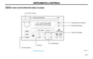 92
92 93
93 94
94 95
95 96
96 97
97 98
98 99
99 100
100 101
101 102
102 103
103 104
104 105
105 106
106 107
107 108
108 109
109 110
110 111
111 112
112 113
113 114
114 115
115 116
116 117
117 118
118 119
119 120
120 121
121 122
122 123
123 124
124 125
125 126
126 127
127 128
128 129
129 130
130 131
131 132
132 133
133 134
134 135
135 136
136 137
137 138
138 139
139 140
140 141
141 142
142 143
143 144
144 145
145 146
146 147
147 148
148 149
149 150
150 151
151 152
152 153
153 154
154 155
155 156
156 157
157 158
158 159
159 160
160 161
161 162
162 163
163 164
164 165
165 166
166 167
167 168
168 169
169 170
170 171
171 172
172