Page 763 of 1767
Wiring Diagram
YEC148A
DTC P0571 BRAKE SWTD27Ti
EC-401
Page 764 of 1767

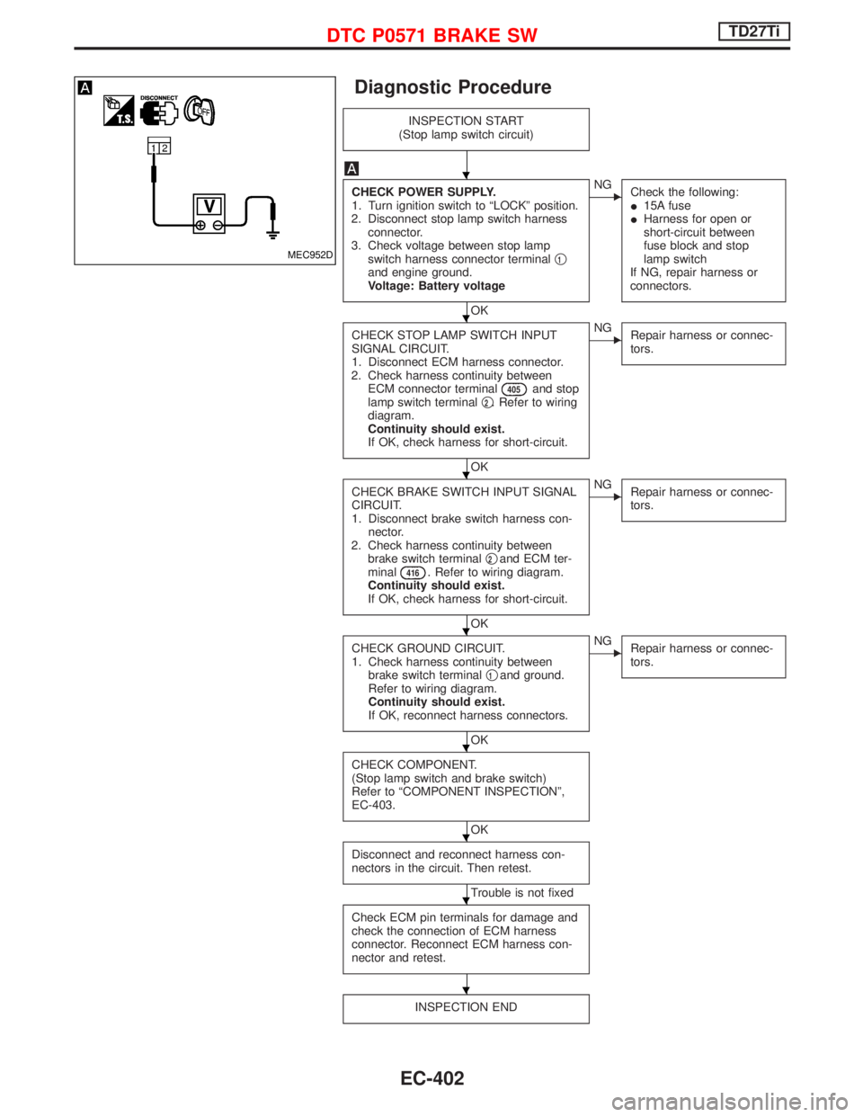
Diagnostic Procedure
INSPECTION START
(Stop lamp switch circuit)
CHECK POWER SUPPLY.
1. Turn ignition switch to ªLOCKº position.
2. Disconnect stop lamp switch harness
connector.
3. Check voltage between stop lamp
switch harness connector terminalq
1and engine ground.
Voltage: Battery voltage
OK
ENG
Check the following:
I15A fuse
IHarness for open or
short-circuit between
fuse block and stop
lamp switch
If NG, repair harness or
connectors.
CHECK STOP LAMP SWITCH INPUT
SIGNAL CIRCUIT.
1. Disconnect ECM harness connector.
2. Check harness continuity between
ECM connector terminal
405and stop
lamp switch terminalq2. Refer to wiring
diagram.
Continuity should exist.
If OK, check harness for short-circuit.
OK
ENG
Repair harness or connec-
tors.
CHECK BRAKE SWITCH INPUT SIGNAL
CIRCUIT.
1. Disconnect brake switch harness con-
nector.
2. Check harness continuity between
brake switch terminalq
2and ECM ter-
minal416. Refer to wiring diagram.
Continuity should exist.
If OK, check harness for short-circuit.
OK
ENG
Repair harness or connec-
tors.
CHECK GROUND CIRCUIT.
1. Check harness continuity between
brake switch terminalq
1and ground.
Refer to wiring diagram.
Continuity should exist.
If OK, reconnect harness connectors.
OK
ENG
Repair harness or connec-
tors.
CHECK COMPONENT.
(Stop lamp switch and brake switch)
Refer to ªCOMPONENT INSPECTIONº,
EC-403.
OK
Disconnect and reconnect harness con-
nectors in the circuit. Then retest.
Trouble is not fixed
Check ECM pin terminals for damage and
check the connection of ECM harness
connector. Reconnect ECM harness con-
nector and retest.
INSPECTION END
MEC952D
H
H
H
H
H
H
H
H
DTC P0571 BRAKE SWTD27Ti
EC-402
Page 767 of 1767
Wiring Diagram
YEC249A
DTC P0650 MITD27Ti
EC-405
Page 768 of 1767

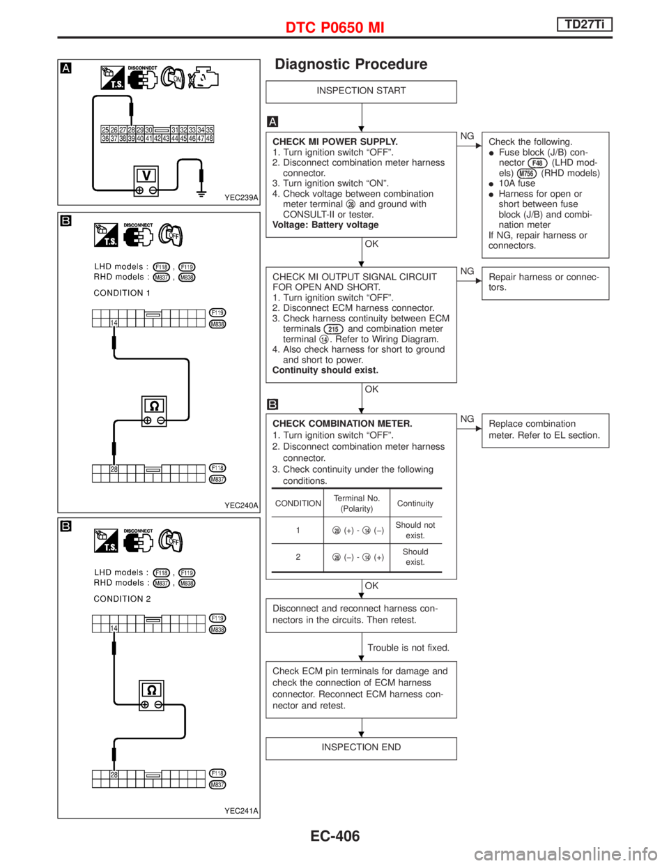
Diagnostic Procedure
INSPECTION START
CHECK MI POWER SUPPLY.
1. Turn ignition switch ªOFFº.
2. Disconnect combination meter harness
connector.
3. Turn ignition switch ªONº.
4. Check voltage between combination
meter terminalq
28and ground with
CONSULT-II or tester.
Voltage: Battery voltage
OK
ENG
Check the following.
IFuse block (J/B) con-
nector
F48(LHD mod-
els)M756(RHD models)
I10A fuse
IHarness for open or
short between fuse
block (J/B) and combi-
nation meter
If NG, repair harness or
connectors.
CHECK MI OUTPUT SIGNAL CIRCUIT
FOR OPEN AND SHORT.
1. Turn ignition switch ªOFFº.
2. Disconnect ECM harness connector.
3. Check harness continuity between ECM
terminals
215and combination meter
terminalq14. Refer to Wiring Diagram.
4. Also check harness for short to ground
and short to power.
Continuity should exist.
OK
ENG
Repair harness or connec-
tors.
CHECK COMBINATION METER.
1. Turn ignition switch ªOFFº.
2. Disconnect combination meter harness
connector.
3. Check continuity under the following
conditions.
OK
ENG
Replace combination
meter. Refer to EL section.
Disconnect and reconnect harness con-
nectors in the circuits. Then retest.
Trouble is not fixed.
Check ECM pin terminals for damage and
check the connection of ECM harness
connector. Reconnect ECM harness con-
nector and retest.
INSPECTION END
CONDITIONTerminal No.
(Polarity)Continuity
1q
28(+) -q14(þ)Should not
exist.
2q
28(þ) -q14(+)Should
exist.
YEC239A
YEC240A
YEC241A
H
H
H
H
H
H
DTC P0650 MITD27Ti
EC-406
Page 773 of 1767
Wiring Diagram
YEC149A
DTC P1206 F/INJ F/B 2TD27Ti
EC-411
Page 774 of 1767

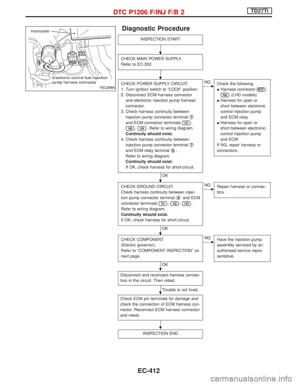
Diagnostic Procedure
INSPECTION START
CHECK MAIN POWER SUPPLY.
Refer to EC-352.
CHECK POWER SUPPLY CIRCUIT.
1. Turn ignition switch to ªLOCKº position.
2. Disconnect ECM harness connector
and electronic injection pump harness
connector.
3. Check harness continuity between
injection pump connector terminalq
7
and ECM connector terminals107,
108,109. Refer to wiring diagram.
Continuity should exist.
4. Check harness continuity between
injection pump connector terminalq
7
and ECM relay terminalq5.
Refer to wiring diagram.
Continuity should exist.
If OK, check harness for short-circuit.
OK
ENG
Check the following.
IHarness connector
M787,
F66(LHD models)
IHarness for open or
short between electronic
control injection pump
and ECM relay
IHarness for open or
short between electronic
control injection pump
and ECM
If NG, repair harness or
connectors.
CHECK GROUND CIRCUIT.
Check harness continuity between injec-
tion pump connector terminalq
4and ECM
connector terminals
101,102,103.
Refer to wiring diagram.
Continuity should exist.
If OK, check harness for short-circuit.
OK
ENG
Repair harness or connec-
tors.
CHECK COMPONENT
(Electric governor).
Refer to ªCOMPONENT INSPECTIONº on
next page.
OK
ENG
Have the injection pump
assembly serviced by an
authorised service repre-
sentative.
Disconnect and reconnect harness connec-
tors in the circuit. Then retest.
Trouble is not fixed.
Check ECM pin terminals for damage and
check the connection of ECM harness con-
nector. Reconnect ECM harness connector
and retest.
INSPECTION END
YEC248A
H
H
H
H
H
H
H
DTC P1206 F/INJ F/B 2TD27Ti
EC-412
Page 777 of 1767
Wiring Diagram
YEC149A
DTC P1207 CONT SLEEV POS SENTD27Ti
EC-415
Page 778 of 1767

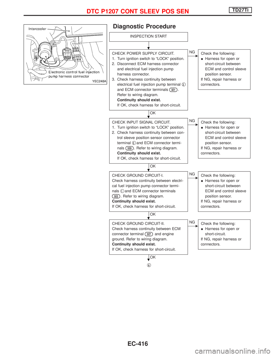
Diagnostic Procedure
INSPECTION START
CHECK POWER SUPPLY CIRCUIT.
1. Turn ignition switch to ªLOCKº position.
2. Disconnect ECM harness connector
and electrical fuel injection pump
harness connector.
3. Check harness continuity between
electrical fuel injection pump terminalq
2
and ECM connector terminals321.
Refer to wiring diagram.
Continuity should exist.
If OK, check harness for short-circuit.
OK
ENG
Check the following:
IHarness for open or
short-circuit between
ECM and control sleeve
position sensor.
If NG, repair harness or
connectors.
CHECK INPUT SIGNAL CIRCUIT.
1. Turn ignition switch to ªLOCKº position.
2. Check harness continuity between con-
trol sleeve position sensor connector
terminalq
3and ECM connector termi-
nals
320. Refer to wiring diagram.
Continuity should exist.
If OK, check harness for short-circuit.
OK
ENG
Check the following:
IHarness for open or
short-circuit between
ECM and control sleeve
position sensor.
If NG, repair harness or
connectors.
CHECK GROUND CIRCUIT-I.
Check harness continuity between electri-
cal fuel injection pump connector termi-
nalsq
1and ECM connector terminals
322. Refer to wiring diagram.
Continuity should exist.
If OK, check harness for short-circuit.
OK
ENG
Check the following:
IHarness for open or
short-circuit between
ECM and control sleeve
position sensor.
If NG, repair harness or
connectors.
CHECK GROUND CIRCUIT-II.
Check harness continuity between ECM
connector terminal
327and engine
ground. Refer to wiring diagram.
Continuity should exist.
If OK, check harness for short-circuit.
OK
ENG
Check the following:
IHarness for open or
short-circuit.
If NG, repair harness or
connectors.
qA
YEC248A
H
H
H
H
H
DTC P1207 CONT SLEEV POS SENTD27Ti
EC-416