Page 139 of 1767
d. Assemble cam ring, cam ring spring and spring seat. Install
spring by pushing it against pump housing.
e. While pushing on cam ring install pivot pin.
3. Install rotor, vanes and vane rings.
IPay attention to direction of rotor.
4. Install oil pump housing and oil pump cover.
a. Wrap masking tape around splines of oil pump cover assembly
to protect seal. Position oil pump cover assembly in oil pump
housing assembly, then remove masking tape.
b. Tighten bolts in a criss-cross pattern.
5. Install new seal rings carefully after packing ring grooves with
petroleum jelly. Press rings down into jelly to a close fit.
ISeal rings come in two different diameters. Check fit care-
fully in each groove.
Small dia. seal ring:
No mark
Large dia. seal ring:
Yellow mark in area shown by arrow
IDo not spread gap of seal ring excessively while installing.
It may deform ring.
SAT661A
SAT651A
SAT662A
SAT649A
YAT341
REPAIR FOR COMPONENT PARTS
Oil Pump (Cont'd)
AT-137
Page 195 of 1767

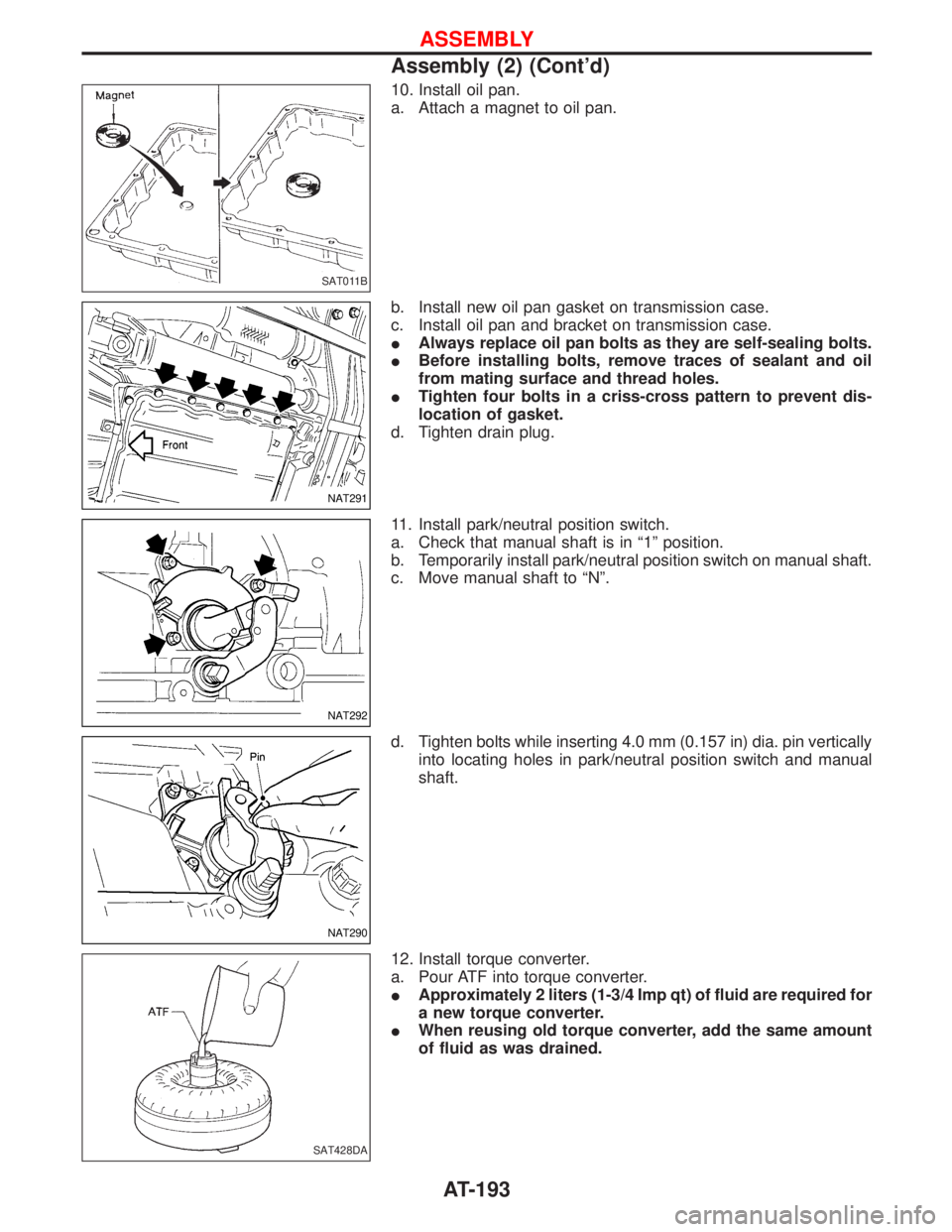
10. Install oil pan.
a. Attach a magnet to oil pan.
b. Install new oil pan gasket on transmission case.
c. Install oil pan and bracket on transmission case.
IAlways replace oil pan bolts as they are self-sealing bolts.
IBefore installing bolts, remove traces of sealant and oil
from mating surface and thread holes.
ITighten four bolts in a criss-cross pattern to prevent dis-
location of gasket.
d. Tighten drain plug.
11. Install park/neutral position switch.
a. Check that manual shaft is in ª1º position.
b. Temporarily install park/neutral position switch on manual shaft.
c. Move manual shaft to ªNº.
d. Tighten bolts while inserting 4.0 mm (0.157 in) dia. pin vertically
into locating holes in park/neutral position switch and manual
shaft.
12. Install torque converter.
a. Pour ATF into torque converter.
IApproximately 2 liters (1-3/4 Imp qt) of fluid are required for
a new torque converter.
IWhen reusing old torque converter, add the same amount
of fluid as was drained.
SAT011B
NAT291
NAT292
NAT290
SAT428DA
ASSEMBLY
Assembly (2) (Cont'd)
AT-193
Page 389 of 1767
Spray pattern test
1. Check spray pattern by pumping tester handle one full stroke
per second.
NG spray pattern:
Does not inject straight and strong (B in the fig-
ure).
Fuel drips (C in the figure).
Does not inject evenly (D in the figure).
2. If the spray pattern is not correct, replace injection nozzle
assembly.
Electronic Control Fuel Injection Pump
REMOVAL AND INSTALLATION
CAUTION:
When removing or installing the timing chain as incidental work of the fuel injection pump removal/
installation, always secure the internal mechanism of the idler gear with bolts before removing or
installing the fuel injection pump sprocket. Do not refer to the procedure for ªTIMING CHAINº in EM
section based on No. 1 cylinder compression top dead center. (Unless otherwise specified.)
JEF349Y
JEF259Z
BASIC SERVICE PROCEDUREZD30DDTi
Injection Tube and Injection Nozzle (Cont'd)
EC-27