Page 337 of 1767
Alignment
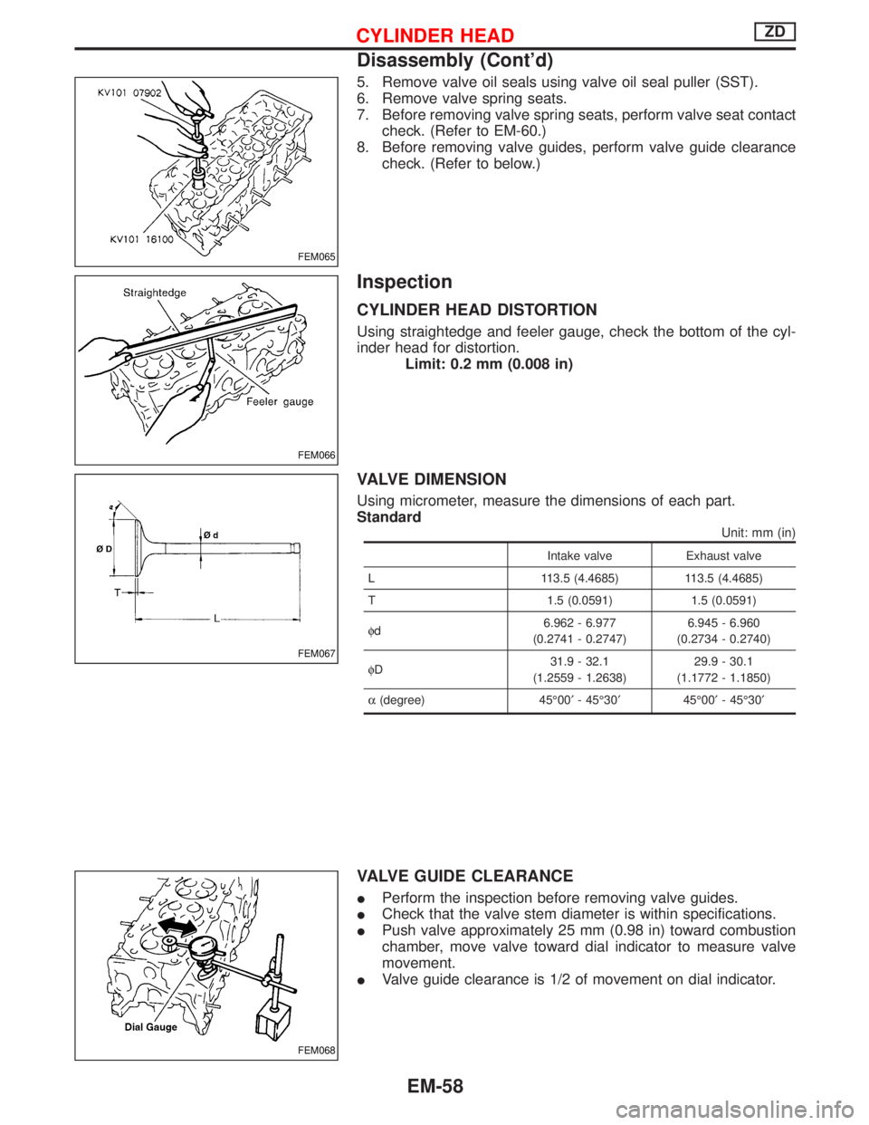
IAll dimensions indicated in figures are actual ones.
IWhen using a tracking gauge, adjust both pointers to equal length. Then check the pointers and gauge
itself to make sure there is no free play.
IWhen a measuring tape is used, check to be sure there is no elongation, twisting or bending.
IMeasurements should be taken at the center of the mounting holes.
IAn asterisk (*) following the value at the measuring point indicates that the measuring point on the other
side is symmetrically the same value.
IThe coordinates of the measurement points are the distances measured from the standard line of ªXº, ªYº
and ªZº.
YBT089
BODY (ALIGNMENT)
BT-49
Page 1114 of 1767
Tool number
Tool nameDescription
KV10109300
Pulley holder
NT628a: 68 mm (2.68 in)
b: 8 mm (0.31 in) dia.
KV111045S1
Balancer shaft bearing
replacer set
q
1KV11104510
Replacer bar
q
2KV11104521
Guide plate
q
3KV11104530
Adapter
(Front bearing)
q
4ST15243000
Drift
NT258
Removing and installing balancer shaft bearing
Commercial Service Tools
Tool name Description
Valve seat cutter set
NT048
Finishing valve seat dimensions
Piston ring compressor
NT044
Installing piston assembly into cylinder bore
Piston ring expander
NT030
Removing and installing piston ring
Standard Universal
NT808
Removing and installing transmission mount
PREPARATIONZD
Special Service Tools (Cont'd)
EM-6
Page 1166 of 1767

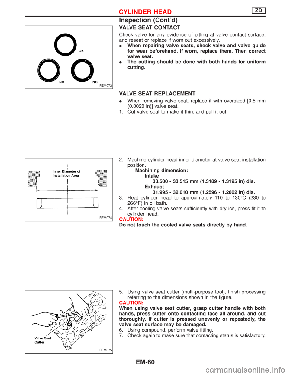
5. Remove valve oil seals using valve oil seal puller (SST).
6. Remove valve spring seats.
7. Before removing valve spring seats, perform valve seat contact
check. (Refer to EM-60.)
8. Before removing valve guides, perform valve guide clearance
check. (Refer to below.)
Inspection
CYLINDER HEAD DISTORTION
Using straightedge and feeler gauge, check the bottom of the cyl-
inder head for distortion.
Limit: 0.2 mm (0.008 in)
VALVE DIMENSION
Using micrometer, measure the dimensions of each part.
Standard
Unit: mm (in)
Intake valve Exhaust valve
L 113.5 (4.4685) 113.5 (4.4685)
T 1.5 (0.0591) 1.5 (0.0591)
fd6.962 - 6.977
(0.2741 - 0.2747)6.945 - 6.960
(0.2734 - 0.2740)
fD31.9 - 32.1
(1.2559 - 1.2638)29.9 - 30.1
(1.1772 - 1.1850)
a(degree) 45É00¢- 45É30¢45É00¢- 45É30¢
VALVE GUIDE CLEARANCE
IPerform the inspection before removing valve guides.
ICheck that the valve stem diameter is within specifications.
IPush valve approximately 25 mm (0.98 in) toward combustion
chamber, move valve toward dial indicator to measure valve
movement.
IValve guide clearance is 1/2 of movement on dial indicator.
FEM065
FEM066
FEM067
FEM068
CYLINDER HEADZD
Disassembly (Cont'd)
EM-58
Page 1168 of 1767

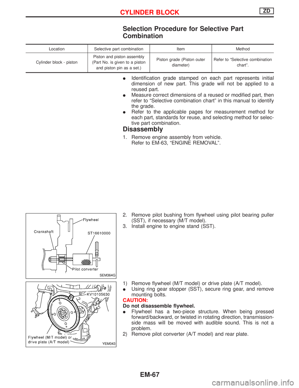
VALVE SEAT CONTACT
Check valve for any evidence of pitting at valve contact surface,
and reseat or replace if worn out excessively.
IWhen repairing valve seats, check valve and valve guide
for wear beforehand. If worn, replace them. Then correct
valve seat.
IThe cutting should be done with both hands for uniform
cutting.
VALVE SEAT REPLACEMENT
IWhen removing valve seat, replace it with oversized [0.5 mm
(0.0020 in)] valve seat.
1. Cut valve seat to make it thin, and pull it out.
2. Machine cylinder head inner diameter at valve seat installation
position.
Machining dimension:
Intake
33.500 - 33.515 mm (1.3189 - 1.3195 in) dia.
Exhaust
31.995 - 32.010 mm (1.2596 - 1.2602 in) dia.
3. Heat cylinder head to approximately 110 to 130ÉC (230 to
266ÉF) in oil bath.
4. After cooling valve seats sufficiently with dry ice, press fit it to
cylinder head.
CAUTION:
Do not touch the cooled valve seats directly by hand.
5. Using valve seat cutter (multi-purpose tool), finish processing
referring to the dimensions shown in the figure.
CAUTION:
When using valve seat cutter, grasp cutter handle with both
hands, press cutter onto contacting face all around, and cut
thoroughly. If cutter is pressed unevenly or repeatedly, the
valve seat surface may be damaged.
6. Using compound, perform valve fitting.
7. Check again to make sure that contacting status is satisfactory.
FEM073
FEM074
FEM075
CYLINDER HEADZD
Inspection (Cont'd)
EM-60
Page 1175 of 1767

Selection Procedure for Selective Part
Combination
Location Selective part combination Item Method
Cylinder block - pistonPiston and piston assembly
(Part No. is given to a piston
and piston pin as a set.)Piston grade (Piston outer
diameter)Refer to ªSelective combination
chartº.
IIdentification grade stamped on each part represents initial
dimension of new part. This grade will not be applied to a
reused part.
IMeasure correct dimensions of a reused or modified part, then
refer to ªSelective combination chartº in this manual to identify
the grade.
IRefer to the applicable pages for measurement method for
each part, standards for reuse, and selecting method for selec-
tive part combination.
Disassembly
1. Remove engine assembly from vehicle.
Refer to EM-63, ªENGINE REMOVALº.
2. Remove pilot bushing from flywheel using pilot bearing puller
(SST), if necessary (M/T model).
3. Install engine to engine stand (SST).
1) Remove flywheel (M/T model) or drive plate (A/T model).
IUsing ring gear stopper (SST), secure ring gear, and remove
mounting bolts.
CAUTION:
Do not disassemble flywheel.
IFlywheel has a two-piece structure. When being pressed
forward/backward, or twisted in rotating direction, transmission-
side mass will be moved with audible sound. This is not a
problem.
2) Remove pilot converter (A/T model) and rear plate.
SEM364G
YEM043
CYLINDER BLOCKZD
EM-67
Page 1184 of 1767

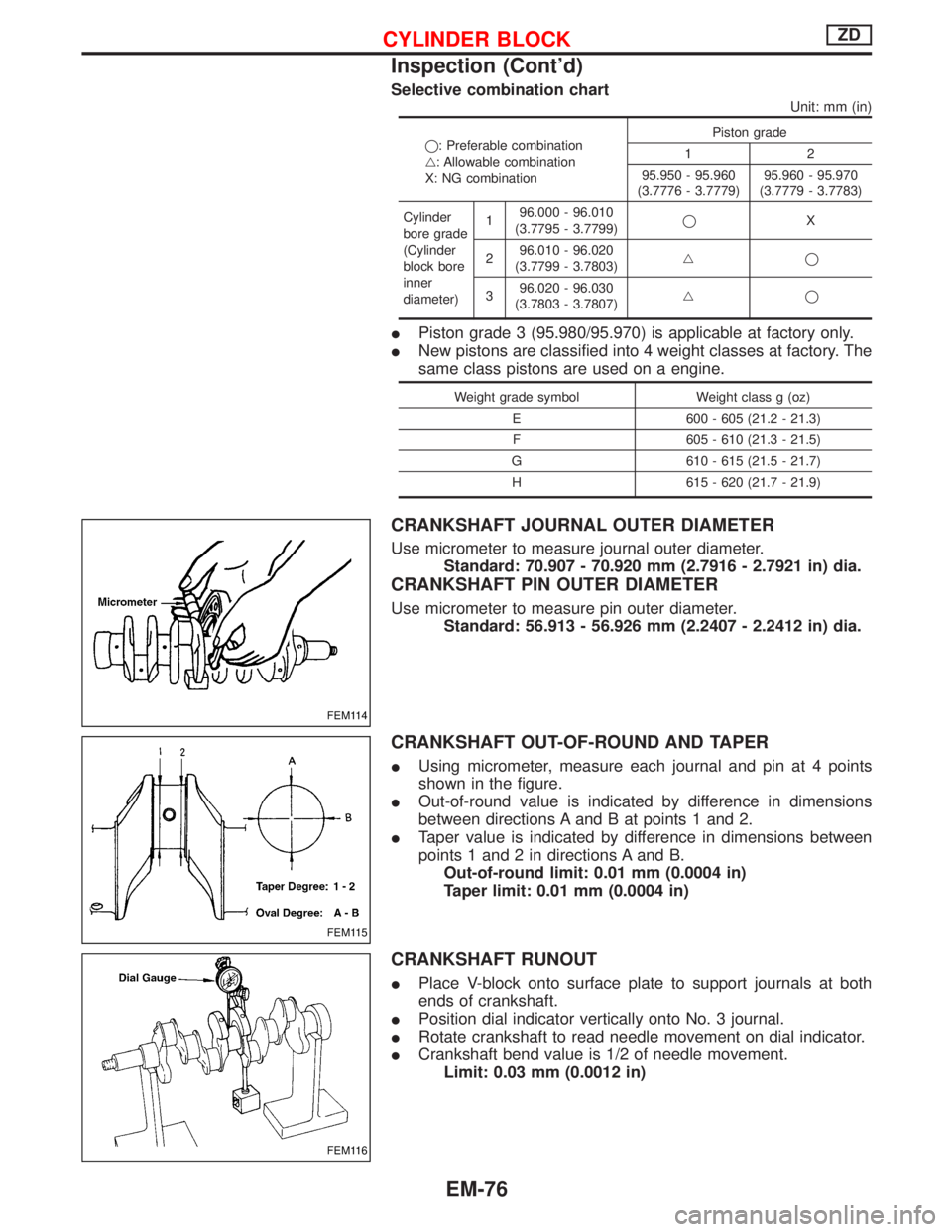
Selective combination chart
Unit: mm (in)
q: Preferable combination
g: Allowable combination
X: NG combinationPiston grade
12
95.950 - 95.960
(3.7776 - 3.7779)95.960 - 95.970
(3.7779 - 3.7783)
Cylinder
bore grade
(Cylinder
block bore
inner
diameter)196.000 - 96.010
(3.7795 - 3.7799)qX
296.010 - 96.020
(3.7799 - 3.7803)gq
396.020 - 96.030
(3.7803 - 3.7807)gq
IPiston grade 3 (95.980/95.970) is applicable at factory only.
INew pistons are classified into 4 weight classes at factory. The
same class pistons are used on a engine.
Weight grade symbol Weight class g (oz)
E 600 - 605 (21.2 - 21.3)
F 605 - 610 (21.3 - 21.5)
G 610 - 615 (21.5 - 21.7)
H 615 - 620 (21.7 - 21.9)
CRANKSHAFT JOURNAL OUTER DIAMETER
Use micrometer to measure journal outer diameter.
Standard: 70.907 - 70.920 mm (2.7916 - 2.7921 in) dia.
CRANKSHAFT PIN OUTER DIAMETER
Use micrometer to measure pin outer diameter.
Standard: 56.913 - 56.926 mm (2.2407 - 2.2412 in) dia.
CRANKSHAFT OUT-OF-ROUND AND TAPER
IUsing micrometer, measure each journal and pin at 4 points
shown in the figure.
IOut-of-round value is indicated by difference in dimensions
between directions A and B at points 1 and 2.
ITaper value is indicated by difference in dimensions between
points 1 and 2 in directions A and B.
Out-of-round limit: 0.01 mm (0.0004 in)
Taper limit: 0.01 mm (0.0004 in)
CRANKSHAFT RUNOUT
IPlace V-block onto surface plate to support journals at both
ends of crankshaft.
IPosition dial indicator vertically onto No. 3 journal.
IRotate crankshaft to read needle movement on dial indicator.
ICrankshaft bend value is 1/2 of needle movement.
Limit: 0.03 mm (0.0012 in)
FEM114
FEM115
FEM116
CYLINDER BLOCKZD
Inspection (Cont'd)
EM-76
Page 1217 of 1767
5. Stake exhaust valve seat at five places with punch.
When staking valve seat, select different places than those
staked before.
6. Cut or grind valve seat using suitable tool at the specified
dimensions. Refer to SDS.
7. After cutting, lap valve seat with a lapping compound.
8. Check contact condition of valve seat.
COMBUSTION CHAMBER
Check combustion chamber for cracks and other damage. If
necessary, replace.
REPLACING COMBUSTION CHAMBER
Usually combustion chamber should not be removed.
1. Remove combustion chamber so that cylinder head cannot be
damaged.
2. Install combustion chamber.
IIdentification of combustion chambers
Identification mark
(on combustion chamber)Outer diameter ªDº
mm (in)
2 37 (1.46)
(1) Cool combustion chamber with dry ice for approximately 5 to 10
minutes.
WARNING:
Do not touch cooled combustion chamber with bare hands.
SEM087
NEM161
EEM116
CYLINDER HEADTD27Ti
Inspection (Cont'd)
EM-109
Page 1218 of 1767
(2) Align combustion chamber knock pin with cylinder head notch,
and drive in combustion chamber with a soft hammer.
3. Check amount of protrusion of combustion chamber.
Protrusion:
Standard
Less than 0.10 mm (0.0039 in)
VALVE DIMENSIONS
Check dimensions in each valve. For dimensions, refer to SDS.
When valve head has been worn down to 0.5 mm (0.020 in) in
margin thickness, replace the valve.
Grinding allowance for valve stem tip is 0.2 mm (0.008 in) or
less.
VALVE SPRING SQUARENESS
Out-of-square ªSº:
Less than 2.0 mm (0.079 in)
VALVE SPRING PRESSURE
Refer to SDS.
SEM634B
SEM188A
SEM635B
EM113
CYLINDER HEADTD27Ti
Inspection (Cont'd)
EM-110