2002 NISSAN TERRANO dimensions
[x] Cancel search: dimensionsPage 1292 of 1767
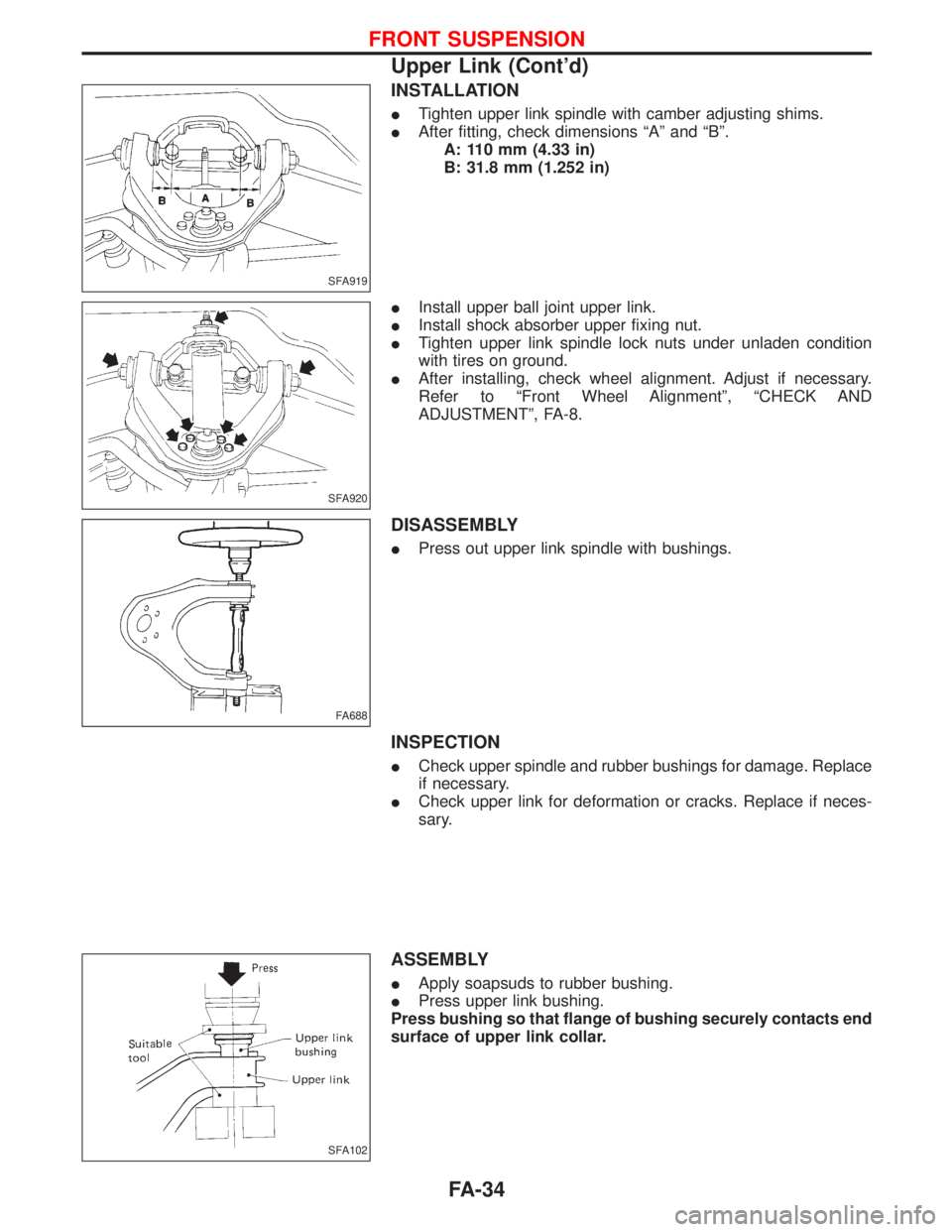
INSTALLATION
ITighten upper link spindle with camber adjusting shims.
IAfter fitting, check dimensions ªAº and ªBº.
A: 110 mm (4.33 in)
B: 31.8 mm (1.252 in)
IInstall upper ball joint upper link.
IInstall shock absorber upper fixing nut.
ITighten upper link spindle lock nuts under unladen condition
with tires on ground.
IAfter installing, check wheel alignment. Adjust if necessary.
Refer to ªFront Wheel Alignmentº, ªCHECK AND
ADJUSTMENTº, FA-8.
DISASSEMBLY
IPress out upper link spindle with bushings.
INSPECTION
ICheck upper spindle and rubber bushings for damage. Replace
if necessary.
ICheck upper link for deformation or cracks. Replace if neces-
sary.
ASSEMBLY
IApply soapsuds to rubber bushing.
IPress upper link bushing.
Press bushing so that flange of bushing securely contacts end
surface of upper link collar.
SFA919
SFA920
FA688
SFA102
FRONT SUSPENSION
Upper Link (Cont'd)
FA-34
Page 1316 of 1767
GENERAL INFORMATION
SECTION
GI
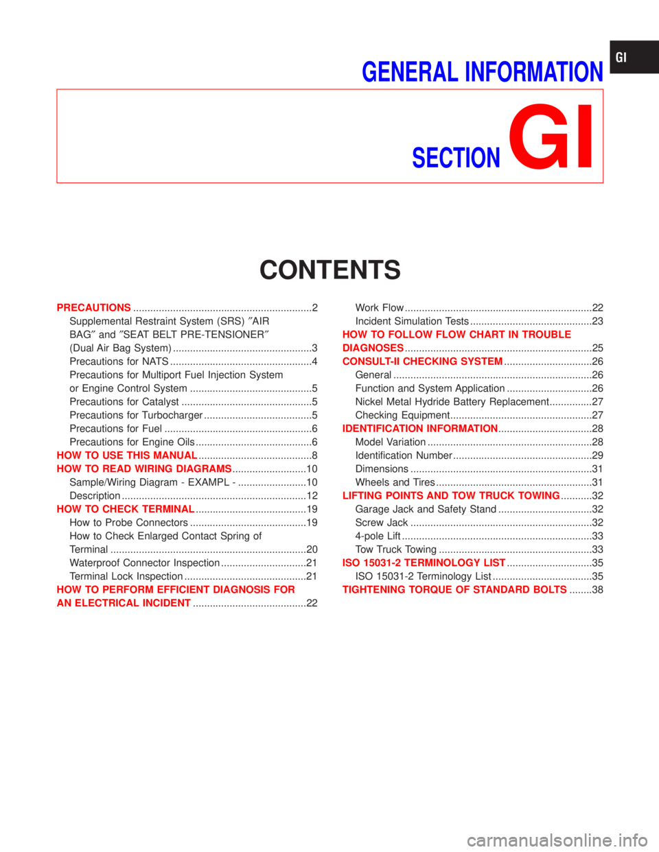
CONTENTS
PRECAUTIONS...............................................................2
Supplemental Restraint System (SRS)²AIR
BAG²and²SEAT BELT PRE-TENSIONER²
(Dual Air Bag System) .................................................3
Precautions for NATS ..................................................4
Precautions for Multiport Fuel Injection System
or Engine Control System ...........................................5
Precautions for Catalyst ..............................................5
Precautions for Turbocharger ......................................5
Precautions for Fuel ....................................................6
Precautions for Engine Oils .........................................6
HOW TO USE THIS MANUAL........................................8
HOW TO READ WIRING DIAGRAMS..........................10
Sample/Wiring Diagram - EXAMPL - ........................10
Description .................................................................12
HOW TO CHECK TERMINAL.......................................19
How to Probe Connectors .........................................19
How to Check Enlarged Contact Spring of
Terminal .....................................................................20
Waterproof Connector Inspection ..............................21
Terminal Lock Inspection ...........................................21
HOW TO PERFORM EFFICIENT DIAGNOSIS FOR
AN ELECTRICAL INCIDENT........................................22Work Flow ..................................................................22
Incident Simulation Tests ...........................................23
HOW TO FOLLOW FLOW CHART IN TROUBLE
DIAGNOSES..................................................................25
CONSULT-II CHECKING SYSTEM...............................26
General ......................................................................26
Function and System Application ..............................26
Nickel Metal Hydride Battery Replacement...............27
Checking Equipment..................................................27
IDENTIFICATION INFORMATION.................................28
Model Variation ..........................................................28
Identification Number .................................................29
Dimensions ................................................................31
Wheels and Tires .......................................................31
LIFTING POINTS AND TOW TRUCK TOWING...........32
Garage Jack and Safety Stand .................................32
Screw Jack ................................................................32
4-pole Lift ...................................................................33
Tow Truck Towing ......................................................33
ISO 15031-2 TERMINOLOGY LIST..............................35
ISO 15031-2 Terminology List ...................................35
TIGHTENING TORQUE OF STANDARD BOLTS........38
Page 1346 of 1767
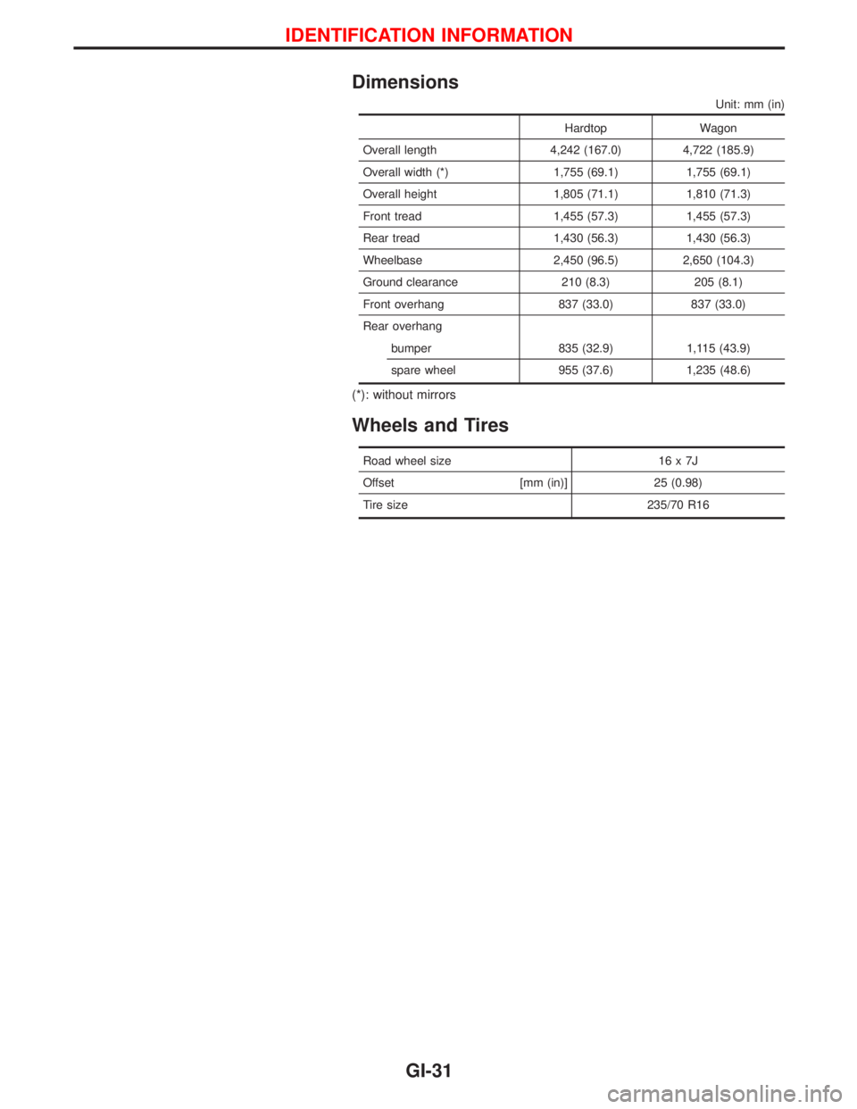
Dimensions
Unit: mm (in)
Hardtop Wagon
Overall length 4,242 (167.0) 4,722 (185.9)
Overall width (*) 1,755 (69.1) 1,755 (69.1)
Overall height 1,805 (71.1) 1,810 (71.3)
Front tread 1,455 (57.3) 1,455 (57.3)
Rear tread 1,430 (56.3) 1,430 (56.3)
Wheelbase 2,450 (96.5) 2,650 (104.3)
Ground clearance 210 (8.3) 205 (8.1)
Front overhang 837 (33.0) 837 (33.0)
Rear overhang
bumper 835 (32.9) 1,115 (43.9)
spare wheel 955 (37.6) 1,235 (48.6)
(*): without mirrors
Wheels and Tires
Road wheel size 16 x 7J
Offset [mm (in)] 25 (0.98)
Tire size 235/70 R16
IDENTIFICATION INFORMATION
GI-31
Page 1420 of 1767
Clutch pedal .............................................CL-3, 4, 5
Clutch release mechanism ...............................CL-9
Coil spring (rear) ......................................RA-14, 16
Collision diagnosis..........................................RS-57
Combination lamp, front, removal and
installation .....................................................BT-6
Combination lamp, rear, removal and
installation .....................................................BT-8
Combination meter (needle type) ...................EL-70
Combination meter removal and instal-
lation - See Instrument panel......................BT-16
Combination switch...................................EL-23, 24
Component Location (manual A/C) ..................HA-7
Compression pressure ...................................EM-10
Compressor clutch removal and
installation ...................................................HA-24
Compressor mounting ....................................HA-21
Connecting rod...............................................EM-73
Connecting rod bearing clearance.................EM-77
Connecting rod bushing clearance ................EM-73
Console box - See Instrument panel ..............BT-16
CONSULT for ABS .........................................BR-58
CONSULT for engine .............................EC-39, 327
CONSULT-II general information.....................GI-26
Control lever (M/T) .........................................MT-13
Control lever (Transfer) .....................................TF-8
Control sleeve position sensor .....................EC-414
Control valve (A/T) ........................................AT-113
COOL/F - Wiring diagram ............................EC-112
Coolant mixture ratio ...................MA-17, 20, 22, 31
Coolant replacement ...............MA-5, 17, 20, 22, 31
Cooling circuit (engine)...............................LC-9, 27
Cooling fan ...............................................LC-15, 33
Cooling fan control .......................................EC-109
Cooling fan relay ..........................................EC-426
Corrosion protection..........................................BT-5
Counter gear (M/T) .........................................MT-11
Counter gear (Transfer) ............................TF-10, 20
Cowl top ..........................................................BT-21
Cowl top cover ................................................BT-21
Crankcase emission control system -
See positive crankcase ventilation .....EC-23, 312
Crankcase ventilation system - See
Positive crankcase ventilation ............EC-23, 312
Crankshaft ......................................................EM-76
Crankshaft position sensor (TDC) .......EC-145, 385
Cylinder block ................................................EM-66
Cylinder head .................................................EM-52
D
Data link connector ................................EC-39, 327
Daytime light system ..........................EL-29, 30, 31
DEF - Wiring diagram ...................................EL-107
Defroster door control rod adjustment ...........HA-62
Diagnosis sensor unit .....................................RS-11
Diagnostic trouble code (DTC) for OBD
system ................................................EC-33, 321
Differential carrier assembly ....................PD-29, 53Differential carrier disassembly..........PD-18, 38, 40
Differential gear oil replacement .......MA-36, 38, 39
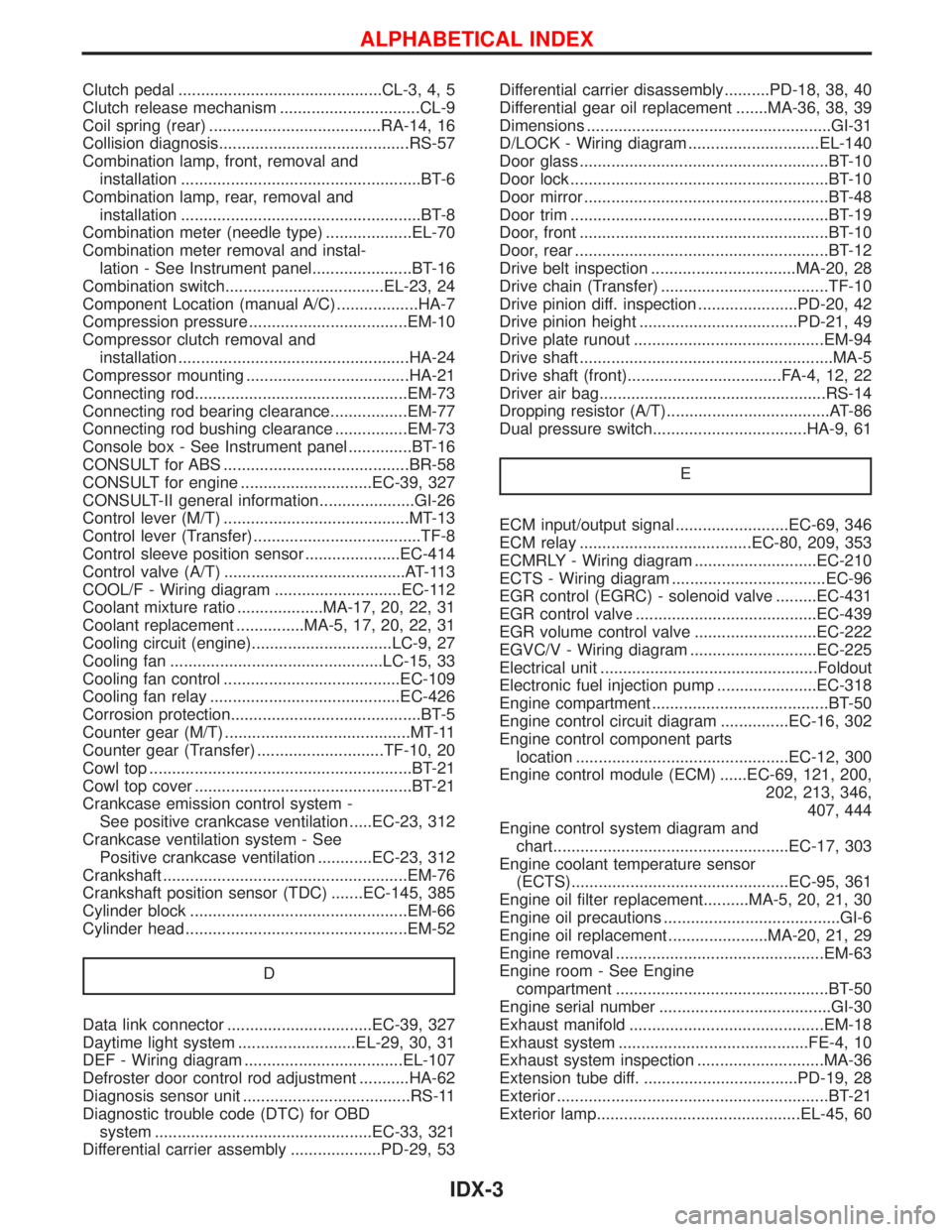
Dimensions ......................................................GI-31
D/LOCK - Wiring diagram .............................EL-140
Door glass .......................................................BT-10
Door lock .........................................................BT-10
Door mirror ......................................................BT-48
Door trim .........................................................BT-19
Door, front .......................................................BT-10
Door, rear ........................................................BT-12
Drive belt inspection ................................MA-20, 28
Drive chain (Transfer) .....................................TF-10
Drive pinion diff. inspection ......................PD-20, 42
Drive pinion height ...................................PD-21, 49
Drive plate runout ..........................................EM-94
Drive shaft ........................................................MA-5
Drive shaft (front)..................................FA-4, 12, 22
Driver air bag..................................................RS-14
Dropping resistor (A/T)....................................AT-86
Dual pressure switch..................................HA-9, 61
E
ECM input/output signal .........................EC-69, 346
ECM relay ......................................EC-80, 209, 353
ECMRLY - Wiring diagram ...........................EC-210
ECTS - Wiring diagram ..................................EC-96
EGR control (EGRC) - solenoid valve .........EC-431
EGR control valve ........................................EC-439
EGR volume control valve ...........................EC-222
EGVC/V - Wiring diagram ............................EC-225
Electrical unit ................................................Foldout
Electronic fuel injection pump ......................EC-318
Engine compartment .......................................BT-50
Engine control circuit diagram ...............EC-16, 302
Engine control component parts
location ...............................................EC-12, 300
Engine control module (ECM) ......EC-69, 121, 200,
202, 213, 346,
407, 444
Engine control system diagram and
chart....................................................EC-17, 303
Engine coolant temperature sensor
(ECTS)................................................EC-95, 361
Engine oil filter replacement..........MA-5, 20, 21, 30
Engine oil precautions .......................................GI-6
Engine oil replacement ......................MA-20, 21, 29
Engine removal ..............................................EM-63
Engine room - See Engine
compartment ...............................................BT-50
Engine serial number ......................................GI-30
Exhaust manifold ...........................................EM-18
Exhaust system ..........................................FE-4, 10
Exhaust system inspection ............................MA-36
Extension tube diff. ..................................PD-19, 28
Exterior ............................................................BT-21
Exterior lamp.............................................EL-45, 60
ALPHABETICAL INDEX
IDX-3
Page 1421 of 1767
F
Fan switch ......................................................HA-60
F/FOG - Wiring diagram .................................EL-51
Final drive disassembly............................PD-15, 37
Final drive pre-inspection .........................PD-15, 37
Final drive removal and installation ...............PD-15
Finisher, interior - See Trim ............................BT-18
Finisher, rear panel .........................................BT-18
Floor trim .........................................................BT-18
Fluid temperature sensor (A/T) .....................AT-141
Fluids .............................................MA-5, 17, 20, 36
Flywheel (clutch) .......................................CL-11, 12
Flywheel runout..............................................EM-94
Fog lamp, front .........................................EL-51, 53
Fog lamp, rear ................................................EL-54
Fork rod (M/T) ................................................MT-13
Forward clutch...............................................AT-157
Front axle ....................................................FA-4, 13
Front bumper ....................................................BT-6
Front case (Transfer) ..................................TF-9, 23
Front combination lamp removal and
installation .....................................................BT-6
Front disc brake .............................................BR-26
Front door .......................................................BT-10
Front Door Trim...............................................BT-19
Front drive shaft (Transfer) .........................TF-9, 19
Front final drive disassembly (4WD) ..............PD-14
Front final drive removal and installa-
tion (4WD) ............................................PD-12, 13
Front fog lamp ..........................................EL-51, 53
Front passenger air bag .................................RS-17
Front seat ........................................................BT-34
Front seat belt ..................................................RS-4
Front seat belt pre-tensioner ..........................RS-12
Front side air bag ...........................................RS-18
Front suspension ........................................FA-4, 29
Fuel cut control (at no load & high
engine speed) .....................................EC-22, 311
Fuel cut solenoid valve ................................EC-376
Fuel cut system ............................................EC-232
Fuel filler lid.......................................................BT-8
Fuel filter replacement...................MA-5, 20, 23, 33
Fuel gauge..................................FE-3, 6, EL-72, 80
Fuel injection system .............................EC-20, 306
Fuel injection timing feed back (Elec-
tronic Fuel Injection Pump) ......................EC-192
Fuel precautions ................................................GI-6
Fuel pump and gauge ..............................FE-3, 6, 7
Fuel system ..................................................FE-3, 6
Fuel tank .......................................................FE-3, 6
Fuel temperature sensor ......................EC-123, 372
Fuse ................................................................EL-17
Fuse and fusible link box .............................Foldout
Fuse block ....................................................Foldout
Fusible link ......................................................EL-17GGarage jack and safety stand .........................GI-32
Gauges .....................................................EL-70, 71
Gear components (M/T) ........MT-11, 14, 16, 21, 23
Generator - See Alternator .............................SC-27
GLOW - Wiring diagram...............................EC-241
Glow control system.....................EC-239, 311, 389
Glow plug .............................................EC-239, 390
Glow relay ............................................EC-241, 396
Grease .........................................MA-17, 39, 40, 44
Ground distribution..........................................EL-18
H
Harness connector ............................................EL-3
Harness connector inspection .........................GI-19
Harness layout ............EL-247, 248, 264, 276, 278,
286, 287, 288, 289, 290
Hazard warning lamp................................EL-55, 56
Headlamp ......EL-26, 29, 30, 31, 37, 38, 39, 42, 43
Headlamp aiming control .............EL-37, 38, 39, 42
Headlamp washer .........................................EL-100
Headlining - See Roof trim .............................BT-20
Heat up switch..............................................EC-258
Heated seat .......................................BT-36, EL-128
HEATER - Wiring diagram .............................HA-41
HEATUP - Wiring diagram ...........................EC-259
Height (Dimensions) ........................................GI-10
HFC134a (R134a) system precaution .............HA-3
HFC134a (R134a) system service
procedure....................................................HA-15
HFC134a (R134a) system service tools ........HA-11
High clutch ....................................................AT-155
H/LAMP - Wiring diagram ............EL-26, 31, 39, 56
Hood..................................................................BT-6
Hood lock system .............................................BT-6
Horn ..............................................................EL-104
HORN - Wiring diagram................................EL-104
How to erase DTC for OBD system ......EC-33, 321
HSEAT - Wiring diagram...............................EL-128
I
Identification .....................................................HA-2
Identification plate .....................................GI-29, 30
Idle speed...............................................EC-50, 338
Idle speed inspection ...............................MA-20, 26
ILL - Wiring diagram .......................................EL-62
Illumination ................................................EL-61, 62
Injection nozzle ......................................EC-24, 313
Injection nozzle inspection ..................MA-5, 20, 25
Injection timing control valve ........................EC-380
INJPMP - Wiring diagram ...EC-126, 164, 171, 178,
185, 195, 235
Instrument panel .............................................BT-16
INT/L - Wiring diagram....................................EL-66
ALPHABETICAL INDEX
IDX-4
Page 1424 of 1767
TAIL/L - Wiring diagram ..................................EL-45
TCM circuit diagram ..........................................AT-7
TCM inspection table ......................................AT-46
TDC Pulse Signal .........................................EC-168
Temperature control cable and linkage
adjustment ..................................................HA-63
THEFT - Wiring diagram...............................EL-214
Theft warning system ...........EL-209, 210, 213, 230
Thermo control amp .................................HA-51, 61
Thermostat................................................LC-12, 31
Third (3rd) seat ...............................................BT-39
THLCNT - Wiring diagram ...........................EC-435
Three way catalyst precautions.........................GI-5
Throttle control solenoid valve .....................EC-435
Throttle position switch ...................................AT-60
Tie-rod .......................................................ST-19, 21
Tie-rod ball joints.............................................ST-20
Tightening torque of standard bolts.................GI-38
Time control system .....................EL-180, 182, 184
Timing chain ...................................................EM-26
Timing gear ....................................................EM-38
Tire rotation ....................................................MA-43
Tooth contact diff. .....................................PD-27, 52
Torque convertor clutch solenoid valve ..AT-72, 141
Torsion bar spring .......................................FA-4, 30
Tow truck towing ..............................................GI-33
Towing point.....................................................GI-34
Transaxle fluid replacement.....................MA-36, 37
Transfer case ..............................................TF-9, 12
Transfer fluid replacement (Part time
4WD model) .........................................MA-36, 37
Transfer oil replacement ..........................MA-36, 38
Transmission case (M/T)..........................MT-10, 14
TRANSMT - Wiring diagram ...........................EL-80
Tread-FR&RR (Dimensions)............................GI-25
Trim...............................................BT-18, 19, 20, 21
Trunk room trim...............................................BT-47
Turbocharger ..................................................EM-14
Turbocharger charge air cooler......................EM-11
Turbocharger precautions..................................GI-5
TURN - Wiring diagram ..................................EL-56
Turn signal lamp .......................................EL-55, 56
U
Under body .....................................................BT-53
Upper link (front susp.) ...................................FA-33
V
Vacuum hose (brake system) ........................BR-19Vacuum hose drawing (Engine
control)................................................EC-18, 304
Vacuum pump .............................EM-24, BR-23, 25
Valve clearance..............................................EM-35
Valve clearance adjustment.....................MA-20, 28
Valve guide ....................................................EM-59
Valve lifter ......................................................EM-32
Valve seat ......................................................EM-60
Valve spring ...................................................EM-61
Variable nozzle turbocharger control
solenoid valve ...........................................EC-281
Vehicle identification number...........................GI-29
Vehicle speed sensor (VSS) ..................EC-99, 397
Ventilator door control rod adjustment ...........HA-61
Viscosity number (SAE)...........................MA-17, 18
VNT - Wiring diagram ..................................EC-283
VSS - Wiring diagram ..................................EC-101
W
WARN - Wiring diagram ...........................EL-82, 93
Warning chime ..........................................EL-81, 93
Warning lamps ..........................................EL-81, 82
Washer, front ...................................................EL-94
Washer, rear....................................................EL-96
Water cock control rod adjustment ................HA-63
Water pump ..............................................LC-11, 29
Water temperature gauge ...............................EL-72
Weatherstrip - See Exterior ............................BT-21
Wheel alignment (front) ....................................FA-8
Wheel balance ...............................................MA-43
Wheel bearing (front axle) ................................FA-6
Wheel bearing (rear) ..................................RA-5, 16
Wheel hub (front) ........................................FA-4, 18
Wheel sensors (ABS)...............................BR-38, 42
Wheel size .......................................................GI-31
WINDOW - Wiring diagram ..........................EL-134
Window, back door .........................................BT-47
Window, door ..................................................BT-42
Window, rear side .....................................BT-42, 43
Window, side - See Rear side window ...........BT-43
Windshield.......................................................BT-42
WIP/R - Wiring diagram ..................................EL-96
WIPER - Wiring diagram ........................EL-94, 100
Wiper and washer.....................................EL-94, 98
Wiper, front......................................................EL-94
Wiper, rear ......................................................EL-96
Wiring Diagram (Cell code) list .....................EL-291
ALPHABETICAL INDEX
IDX-7
Page 1518 of 1767
IRaise the unit with a hoist.
IPosition the transmission assembly on a portable jack and
secure it with a suitable tool.
Lift the assembly until the gearbox input shaft faces its hous-
ing.
Move the assembly towards the engine. The assembly must be
rotated slightly so that the starter motor housing clears the
projection on the companion floor. Insert input shaft into its
housing (slightly raising the rear of the transfer box may facili-
tate the introduction of the shaft into its housing).
ITighten the screws securing the gearbox to the engine.
:39-49N×m (4.0 - 5.0 kg-m, 29 - 36 ft-lb)
IConnect the electrical wiring. Secure with the respective clips.
IFit the RPM-sensor to the transmission upper side.
IFit the exhaust pipe support bracket to the transfer box.
:13-16N×m (1.3 - 1.6 kg-m,9-12ft-lb)
IFit the starter motor. Secure the earth wire to the starter motor
lower screw.
:31-41N×m (3.2 - 4.2 kg-m, 23 - 30 ft-lb)
IFit the clutch slave cylinder.
:30-40N×m (3.1 - 4.1 kg-m, 22 - 30 ft-lb)
IInstall fourth crossmember (Note the ªfrontº mark).
Crossmember fixing bolts to chassis:
:41-52N×m (4.2 - 5.3 kg-m, 30 - 38 ft-lb)
Crossmember fixing bolts to transmission:
:68-87N×m (6.9 - 8.9 kg-m, 50 - 64 ft-lb)
ITake away the portable jack holding boxes assembly.
IInstall fifth crossmember.
:59-78N×m (6.0 - 8.0 kg-m, 43 - 58 ft-lb)
IInstall third crossmember.
: Screws: 41 - 52 N×m (4.2 - 5.3 kg-m,
30 - 38 ft-lb)
Nuts: 68 - 87 N×m (6.9 - 8.9 kg-m,
50 - 64 ft-lb)
IInstall torsion bar springs. Ð Refer to FA section.
IInstall front and rear propeller shafts. Ð Refer to PD section.
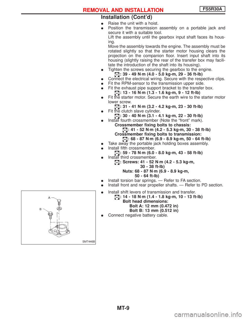
IInstall shift levers of transmission and transfer.
:14-18N×m (1.4 - 1.8 kg-m, 10 - 13 ft-lb)
Bolt head dimensions:
Bolt A: 12 mm (0.472 in)
Bolt B: 13 mm (0.512 in)
IConnect negative battery cable.
SMT446B
REMOVAL AND INSTALLATIONFS5R30A
Installation (Cont'd)
MT-9