2002 NISSAN TERRANO flat tire
[x] Cancel search: flat tirePage 276 of 1767
qA
Note Note
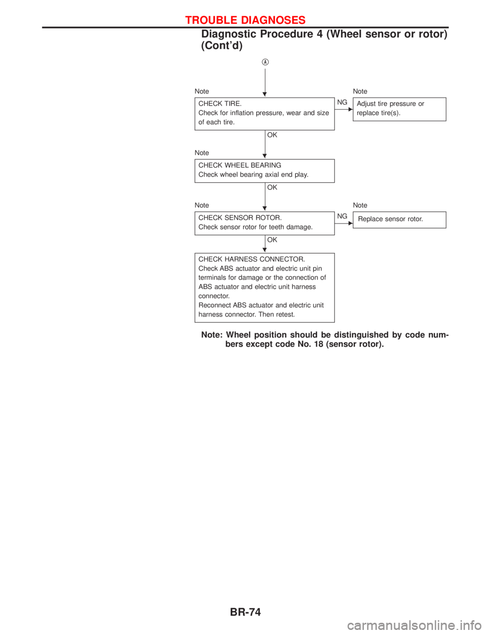
CHECK TIRE.
Check for inflation pressure, wear and size
of each tire.
OK
ENG
Adjust tire pressure or
replace tire(s).
Note
CHECK WHEEL BEARING
Check wheel bearing axial end play.
OK
Note Note
CHECK SENSOR ROTOR.
Check sensor rotor for teeth damage.
OK
ENG
Replace sensor rotor.
CHECK HARNESS CONNECTOR.
Check ABS actuator and electric unit pin
terminals for damage or the connection of
ABS actuator and electric unit harness
connector.
Reconnect ABS actuator and electric unit
harness connector. Then retest.
Note: Wheel position should be distinguished by code num-
bers except code No. 18 (sensor rotor).
H
H
H
H
TROUBLE DIAGNOSES
Diagnostic Procedure 4 (Wheel sensor or rotor)
(Cont'd)
BR-74
Page 859 of 1767
Bulb Replacement
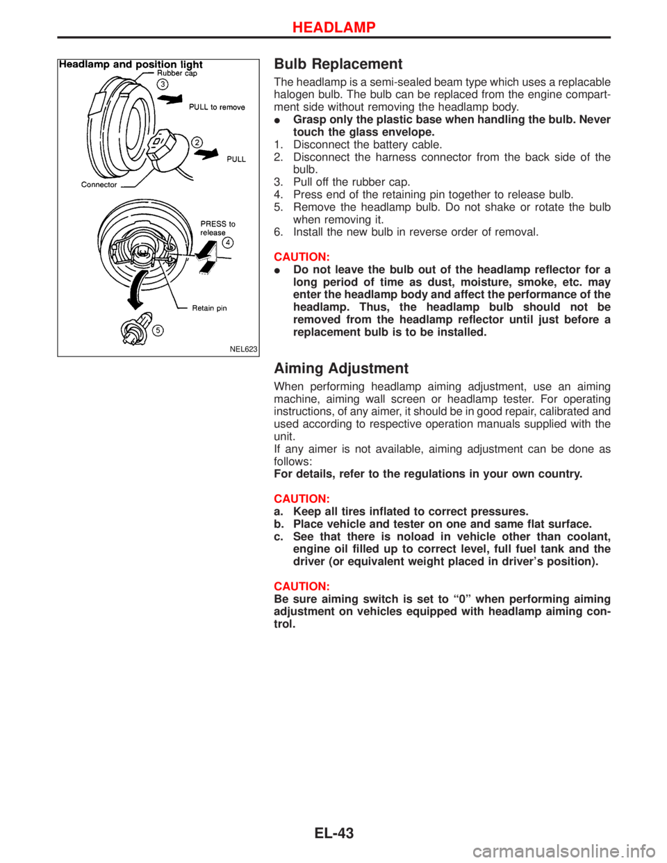
The headlamp is a semi-sealed beam type which uses a replacable
halogen bulb. The bulb can be replaced from the engine compart-
ment side without removing the headlamp body.
IGrasp only the plastic base when handling the bulb. Never
touch the glass envelope.
1. Disconnect the battery cable.
2. Disconnect the harness connector from the back side of the
bulb.
3. Pull off the rubber cap.
4. Press end of the retaining pin together to release bulb.
5. Remove the headlamp bulb. Do not shake or rotate the bulb
when removing it.
6. Install the new bulb in reverse order of removal.
CAUTION:
IDo not leave the bulb out of the headlamp reflector for a
long period of time as dust, moisture, smoke, etc. may
enter the headlamp body and affect the performance of the
headlamp. Thus, the headlamp bulb should not be
removed from the headlamp reflector until just before a
replacement bulb is to be installed.
Aiming Adjustment
When performing headlamp aiming adjustment, use an aiming
machine, aiming wall screen or headlamp tester. For operating
instructions, of any aimer, it should be in good repair, calibrated and
used according to respective operation manuals supplied with the
unit.
If any aimer is not available, aiming adjustment can be done as
follows:
For details, refer to the regulations in your own country.
CAUTION:
a. Keep all tires inflated to correct pressures.
b. Place vehicle and tester on one and same flat surface.
c. See that there is noload in vehicle other than coolant,
engine oil filled up to correct level, full fuel tank and the
driver (or equivalent weight placed in driver's position).
CAUTION:
Be sure aiming switch is set to ª0º when performing aiming
adjustment on vehicles equipped with headlamp aiming con-
trol.
NEL623
HEADLAMP
EL-43
Page 869 of 1767
Front Fog Lamp Aiming Adjustment
When performing fog lamp aiming adjustment, use an aiming
machine, aiming wall screen or headlamp tester. The aimer should
be in good operational condition, calibrated and used according to
the relevant operation manuals supplied with the unit.
If an aimer is not available, aiming adjustment can be done as fol-
lows:
For details, refer to the regulations in your own country.
CAUTION:
IKeep all tires inflated to correct pressures.
IPlace vehicle and tester on one and the same flat surface.
IEnsure that there is no-load in the vehicle other than
coolant, engine oil (filled up to correct level), full fuel tank
and the driver (or equivalent weight placed in driver's posi-
tion).
For details of front fog lamp aiming adjustment, refer to ªAiming
Adjustmentº, EL-43.
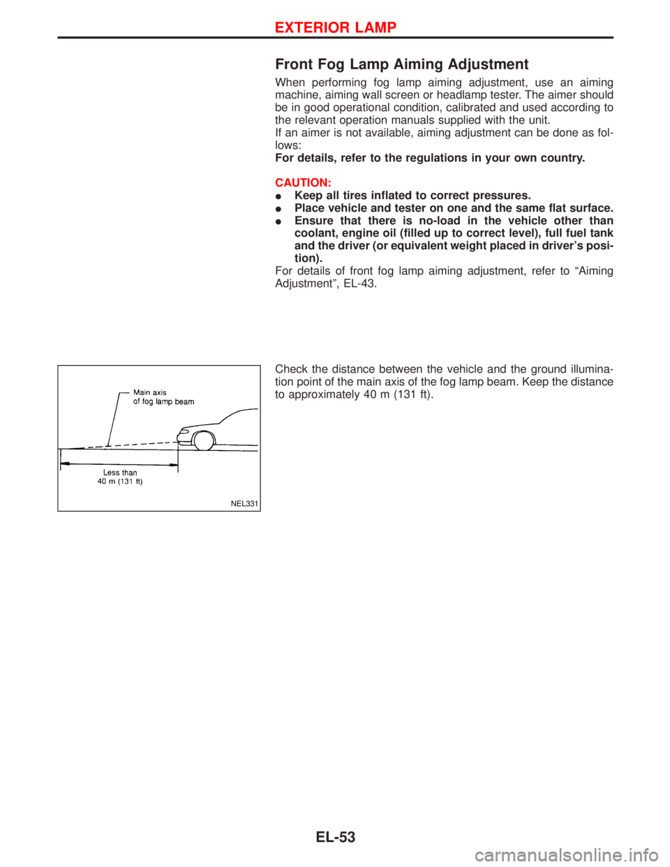
Check the distance between the vehicle and the ground illumina-
tion point of the main axis of the fog lamp beam. Keep the distance
to approximately 40 m (131 ft).
NEL331
EXTERIOR LAMP
EL-53
Page 1266 of 1767
Front Wheel Alignment
Before checking front wheel alignment, be sure to make a prelimi-
nary inspection.
PRELIMINARY INSPECTION
1. Check the tires for wear and proper inflation.
2. Check the wheel runout.
Wheel runout:
Refer to SDS, FA-39.
3. Check the front wheel bearings for looseness.
4. Check the front suspension for looseness.
5. Check the steering linkage for looseness.
6. Check that the front shock absorbers work properly by using
the standard bounce test.
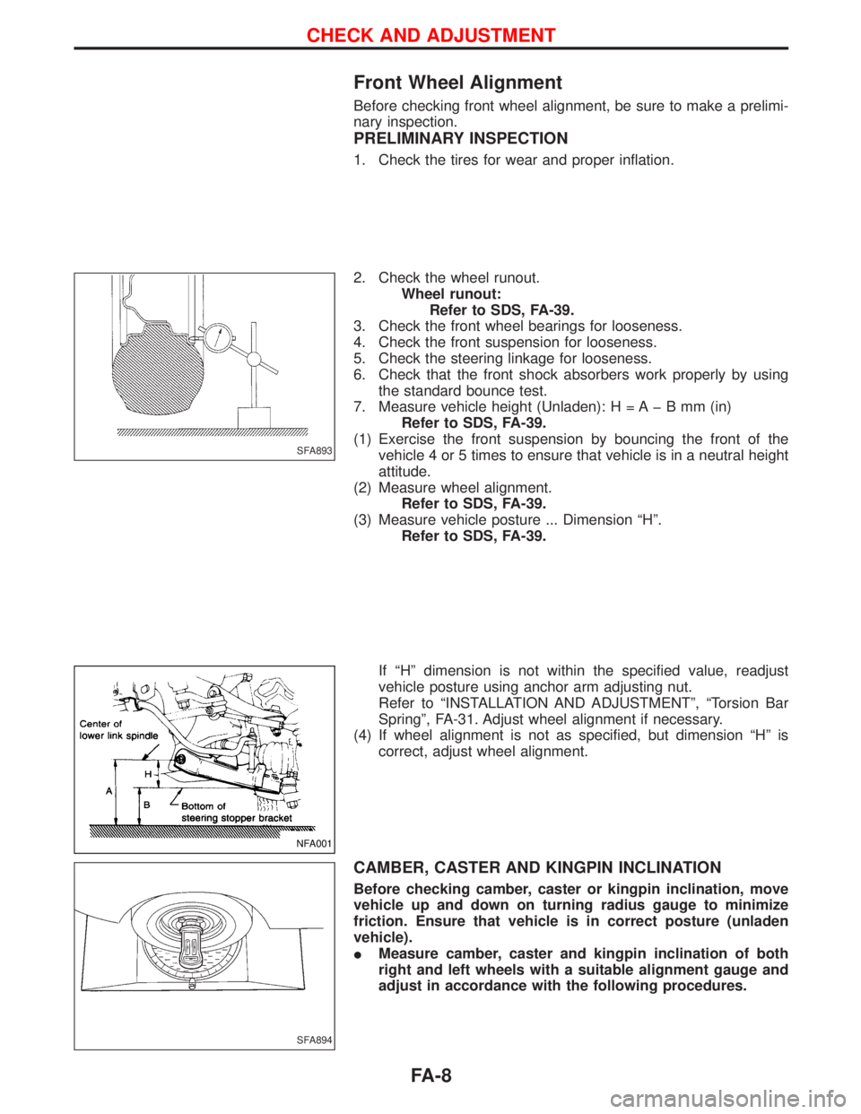
7. Measure vehicle height (Unladen): H = A þ B mm (in)
Refer to SDS, FA-39.
(1) Exercise the front suspension by bouncing the front of the
vehicle 4 or 5 times to ensure that vehicle is in a neutral height
attitude.
(2) Measure wheel alignment.
Refer to SDS, FA-39.
(3) Measure vehicle posture ... Dimension ªHº.
Refer to SDS, FA-39.
If ªHº dimension is not within the specified value, readjust
vehicle posture using anchor arm adjusting nut.
Refer to ªINSTALLATION AND ADJUSTMENTº, ªTorsion Bar
Springº, FA-31. Adjust wheel alignment if necessary.
(4) If wheel alignment is not as specified, but dimension ªHº is
correct, adjust wheel alignment.
CAMBER, CASTER AND KINGPIN INCLINATION
Before checking camber, caster or kingpin inclination, move
vehicle up and down on turning radius gauge to minimize
friction. Ensure that vehicle is in correct posture (unladen
vehicle).
IMeasure camber, caster and kingpin inclination of both
right and left wheels with a suitable alignment gauge and
adjust in accordance with the following procedures.
SFA893
NFA001
SFA894
CHECK AND ADJUSTMENT
FA-8
Page 1627 of 1767
Precautions
SUPPLEMENTAL RESTRAINT SYSTEM (SRS) ªAIR BAGº AND ªSEAT BELT
PRE-TENSIONERº
The Supplemental Restraint System such as ªAIR BAGº and ªSEAT BELT PRE-TENSIONERº used along with
a seat belt, helps to reduce the risk or severity of injury to the driver and front passenger for certain types of
collision. The SRS composition which is available to NISSAN MODEL R20 is as follows (The composition
varies according to the destination and optional equipment.):
IFor a frontal collision
The Supplemental Restraint System consists of driver air bag module (located in the center of the steer-
ing wheel), front passenger air bag module (located on the instrument panel on passenger side), front seat
belt pre-tensioners, a diagnosis sensor unit, warning lamp, wiring harness and spiral cable.
IFor a side collision
The Supplemental Restraint System consists of front side air bag module (located in the outer side of front
seat), side air bag (satellite) sensor, diagnosis sensor unit (one of components of air bags for a frontal
collision), wiring harness, warning lamp (one of components of air bags for a frontal collision).
WARNING:
ITo avoid rendering the SRS inoperative, which could increase the risk of personal injury or death
in the event of a collision which would result in air bag inflation, all maintenance should be per-
formed by an authorized NISSAN dealer.
IImproper maintenance, including incorrect removal and installation of the SRS, can lead to per-
sonal injury caused by unintentional activation of the system.
IDo not use electrical test equipment on any circuit related to the SRS unless instructed to in this
Service Manual. Spiral cable and wiring harnesses covered with yellow insulation tape either just
before the harness connectors or for the complete harness are related to the SRS.
PRECAUTIONS FOR SRS ªAIR BAGº AND ªSEAT BELT PRE-TENSIONERº SERVICE
IDo not use electrical test equipment to check SRS circuits unless instructed to in this Service Manual.
IBefore servicing the SRS, turn ignition switch ªOFFº, disconnect both battery cables and wait at least 3
minutes.
For approximately 3 minutes after the cables are removed, it is still possible for the air bag and seat belt
pre-tensioner to deploy. Therefore, do not work on any SRS connectors or wires until at least 3 minutes
have passed.
IDiagnosis sensor unit must always be installed with their arrow marks ª+º pointing towards the front of
the vehicle for proper operation. Also check diagnosis sensor unit for cracks, deformities or rust before
installation and replace as required.
IThe spiral cable must be aligned with the neutral position since its rotations are limited. Do not attempt to
turn steering wheel or column after removal of steering gear.
IHandle air bag module carefully. Always place driver and front passenger air bag modules with the pad
side facing upward and place front side air bag module (built-in type) standing with stud bolt side setting
bottom.
IConduct self-diagnosis to check entire SRS for proper function after replacing any components.
IAfter air bag inflates, the front instrument panel assembly should be replaced if damaged.
WIRING DIAGRAMS AND TROUBLE DIAGNOSIS
When you read wiring diagrams, refer to the following:
IGI-10, ªHOW TO READ WIRING DIAGRAMSº
IEL-6, ªPOWER SUPPLY ROUTINGº for power distribution circuit
When you perform trouble diagnosis, refer to the following:
IGI-25, ªHOW TO FOLLOW TEST GROUPS IN TROUBLE DIAGNOSISº
IGI-22, ªHOW TO PERFORM EFFICIENT DIAGNOSES FOR AN ELECTRICAL INCIDENTº
SUPPLEMENTAL RESTRAINT SYSTEM (SRS)
RS-6
Page 1639 of 1767
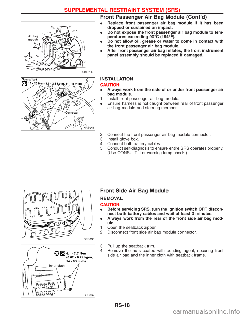
IReplace front passenger air bag module if it has been
dropped or sustained an impact.
IDo not expose the front passenger air bag module to tem-
peratures exceeding 90ÉC (194ÉF).
IDo not allow oil, grease or water to come in contact with
the front passenger air bag module.
IAfter front passenger air bag inflates, the front instrument
panel assembly should be replaced if damaged.
INSTALLATION
CAUTION:
IAlways work from the side of or under front passenger air
bag module.
1. Install front passenger air bag module.
IEnsure harness is not caught between rear of front passenger
air bag module and steering member.
2. Connect the front passenger air bag module connector.
3. Install glove box.
4. Connect both battery cables.
5. Conduct self-diagnosis to ensure entire SRS operates properly.
(Use CONSULT-II or warning lamp check.)
Front Side Air Bag Module
REMOVAL
CAUTION:
IBefore servicing SRS, turn the ignition switch OFF, discon-
nect both battery cables and wait at least 3 minutes.
IAlways work from the rear of the front side air bag mod-
ule.
1. Open the seatback zipper.
2. Disconnect front side air bag module connector.
3. Pull up the seatback trim.
4. Remove the nuts coated with bonding agent, securing front
side air bag and the inner cloth with seatback frame.
SBF814E
NRS046
SRS866
SRS867
SUPPLEMENTAL RESTRAINT SYSTEM (SRS)
Front Passenger Air Bag Module (Cont'd)
RS-18
Page 1717 of 1767
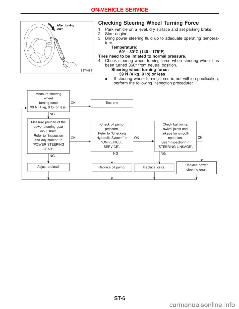
Checking Steering Wheel Turning Force
1. Park vehicle on a level, dry surface and set parking brake.
2. Start engine.
3. Bring power steering fluid up to adequate operating tempera-
ture.
Temperature:
60É - 80ÉC (140 - 176ÉF)
Tires need to be inflated to normal pressure.
4. Check steering wheel turning force when steering wheel has
been turned 360É from neutral position.
Steering wheel turning force:
39 N (4 kg, 9 lb) or less
IIf steering wheel turning force is not within specification,
perform the following inspection procedure:
E
Measure steering
wheel
turning force
39 N (4 kg, 9 lb) or less.
NG
EOK Test end
Measure preload of the
power steering gear
input shaft.
Refer to ªInspection
and Adjustmentº in
ªPOWER STEERING
GEARº.
NG
EOKCheck oil pump
pressure.
Refer to ªChecking
Hydraulic Systemº in
ªON-VEHICLE
SERVICEº.
NG
EOKCheck ball joints,
swivel joints and
linkage for smooth
operation.
See ªInspectionº in
ªSTEERING LINKAGEº.
NGOK
Adjust preload.Replace oil pump.Replace joints.Replace power
steering gear.
SST108B
H
HHHH
HHHH
ON-VEHICLE SERVICE
ST-6