2002 NISSAN TERRANO check engine light
[x] Cancel search: check engine lightPage 22 of 1767
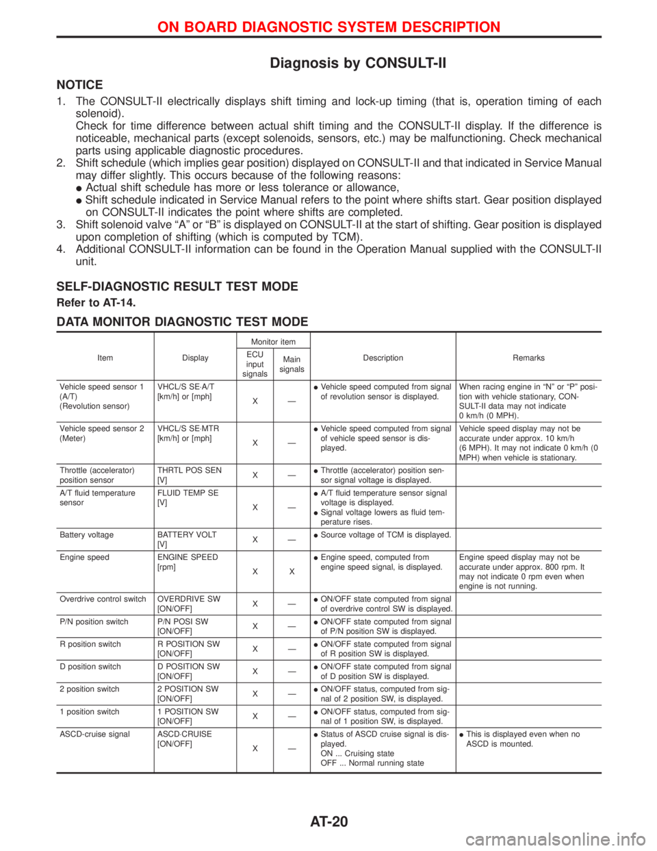
Diagnosis by CONSULT-II
NOTICE
1. The CONSULT-II electrically displays shift timing and lock-up timing (that is, operation timing of each
solenoid).
Check for time difference between actual shift timing and the CONSULT-II display. If the difference is
noticeable, mechanical parts (except solenoids, sensors, etc.) may be malfunctioning. Check mechanical
parts using applicable diagnostic procedures.
2. Shift schedule (which implies gear position) displayed on CONSULT-II and that indicated in Service Manual
may differ slightly. This occurs because of the following reasons:
IActual shift schedule has more or less tolerance or allowance,
IShift schedule indicated in Service Manual refers to the point where shifts start. Gear position displayed
on CONSULT-II indicates the point where shifts are completed.
3. Shift solenoid valve ªAº or ªBº is displayed on CONSULT-II at the start of shifting. Gear position is displayed
upon completion of shifting (which is computed by TCM).
4. Additional CONSULT-II information can be found in the Operation Manual supplied with the CONSULT-II
unit.
SELF-DIAGNOSTIC RESULT TEST MODE
Refer to AT-14.
DATA MONITOR DIAGNOSTIC TEST MODE
Item DisplayMonitor item
Description Remarks ECU
input
signalsMain
signals
Vehicle speed sensor 1
(A/T)
(Revolution sensor)VHCL/S SE×A/T
[km/h] or [mph]
XÐIVehicle speed computed from signal
of revolution sensor is displayed.When racing engine in ªNº or ªPº posi-
tion with vehicle stationary, CON-
SULT-II data may not indicate
0 km/h (0 MPH).
Vehicle speed sensor 2
(Meter)VHCL/S SE×MTR
[km/h] or [mph]
XÐIVehicle speed computed from signal
of vehicle speed sensor is dis-
played.Vehicle speed display may not be
accurate under approx. 10 km/h
(6 MPH). It may not indicate 0 km/h (0
MPH) when vehicle is stationary.
Throttle (accelerator)
position sensorTHRTL POS SEN
[V]XÐIThrottle (accelerator) position sen-
sor signal voltage is displayed.
A/T fluid temperature
sensorFLUID TEMP SE
[V]
XÐIA/T fluid temperature sensor signal
voltage is displayed.
ISignal voltage lowers as fluid tem-
perature rises.
Battery voltage BATTERY VOLT
[V]XÐISource voltage of TCM is displayed.
Engine speed ENGINE SPEED
[rpm]
XXIEngine speed, computed from
engine speed signal, is displayed.Engine speed display may not be
accurate under approx. 800 rpm. It
may not indicate 0 rpm even when
engine is not running.
Overdrive control switch OVERDRIVE SW
[ON/OFF]XÐION/OFF state computed from signal
of overdrive control SW is displayed.
P/N position switch P/N POSI SW
[ON/OFF]XÐION/OFF state computed from signal
of P/N position SW is displayed.
R position switch R POSITION SW
[ON/OFF]XÐION/OFF state computed from signal
of R position SW is displayed.
D position switch D POSITION SW
[ON/OFF]XÐION/OFF state computed from signal
of D position SW is displayed.
2 position switch 2 POSITION SW
[ON/OFF]XÐION/OFF status, computed from sig-
nal of 2 position SW, is displayed.
1 position switch 1 POSITION SW
[ON/OFF]XÐION/OFF status, computed from sig-
nal of 1 position SW, is displayed.
ASCD-cruise signal ASCD×CRUISE
[ON/OFF]
XÐIStatus of ASCD cruise signal is dis-
played.
ON ... Cruising state
OFF ... Normal running stateIThis is displayed even when no
ASCD is mounted.
ON BOARD DIAGNOSTIC SYSTEM DESCRIPTION
AT-20
Page 26 of 1767
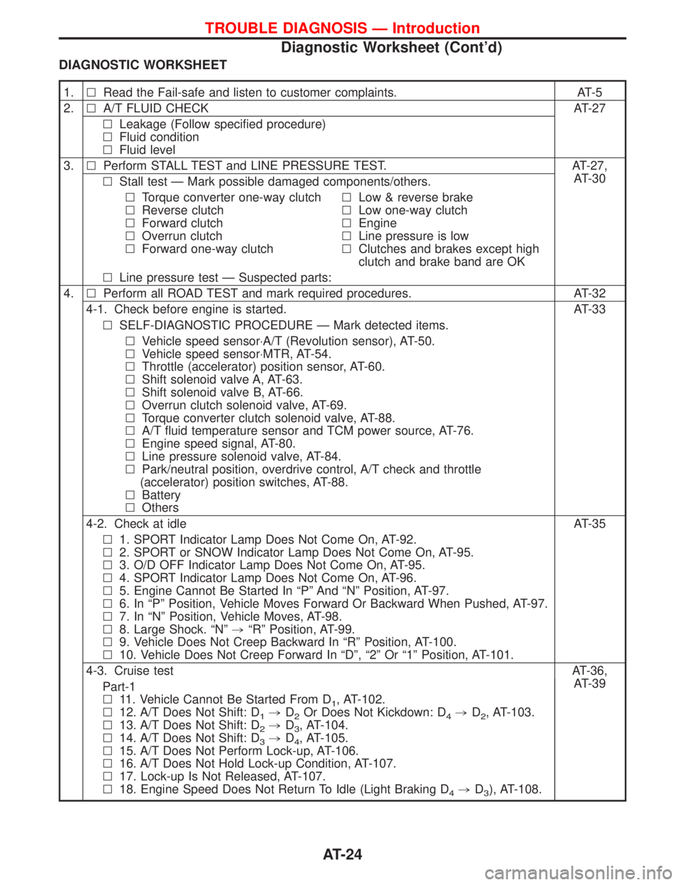
DIAGNOSTIC WORKSHEET
1.lRead the Fail-safe and listen to customer complaints. AT-5
2.lA/T FLUID CHECK AT-27
lLeakage (Follow specified procedure)
lFluid condition
lFluid level
3.lPerform STALL TEST and LINE PRESSURE TEST. AT-27,
AT-30
lStall test Ð Mark possible damaged components/others.
lTorque converter one-way clutch
lReverse clutch
lForward clutch
lOverrun clutch
lForward one-way clutchlLow & reverse brake
lLow one-way clutch
lEngine
lLine pressure is low
lClutches and brakes except high
clutch and brake band are OK
lLine pressure test Ð Suspected parts:
4.lPerform all ROAD TEST and mark required procedures. AT-32
4-1. Check before engine is started. AT-33
lSELF-DIAGNOSTIC PROCEDURE Ð Mark detected items.
lVehicle speed sensor×A/T (Revolution sensor), AT-50.
lVehicle speed sensor×MTR, AT-54.
lThrottle (accelerator) position sensor, AT-60.
lShift solenoid valve A, AT-63.
lShift solenoid valve B, AT-66.
lOverrun clutch solenoid valve, AT-69.
lTorque converter clutch solenoid valve, AT-88.
lA/T fluid temperature sensor and TCM power source, AT-76.
lEngine speed signal, AT-80.
lLine pressure solenoid valve, AT-84.
lPark/neutral position, overdrive control, A/T check and throttle
(accelerator) position switches, AT-88.
lBattery
lOthers
4-2. Check at idle AT-35
l1. SPORT Indicator Lamp Does Not Come On, AT-92.
l2. SPORT or SNOW Indicator Lamp Does Not Come On, AT-95.
l3. O/D OFF Indicator Lamp Does Not Come On, AT-95.
l4. SPORT Indicator Lamp Does Not Come On, AT-96.
l5. Engine Cannot Be Started In ªPº And ªNº Position, AT-97.
l6. In ªPº Position, Vehicle Moves Forward Or Backward When Pushed, AT-97.
l7. In ªNº Position, Vehicle Moves, AT-98.
l8. Large Shock. ªNº,ªRº Position, AT-99.
l9. Vehicle Does Not Creep Backward In ªRº Position, AT-100.
l10. Vehicle Does Not Creep Forward In ªDº, ª2º Or ª1º Position, AT-101.
4-3. Cruise testAT-36,
AT-39
Part-1
l11. Vehicle Cannot Be Started From D
1, AT-102.
l12. A/T Does Not Shift: D
1,D2Or Does Not Kickdown: D4,D2, AT-103.
l13. A/T Does Not Shift: D
2,D3, AT-104.
l14. A/T Does Not Shift: D
3,D4, AT-105.
l15. A/T Does Not Perform Lock-up, AT-106.
l16. A/T Does Not Hold Lock-up Condition, AT-107.
l17. Lock-up Is Not Released, AT-107.
l18. Engine Speed Does Not Return To Idle (Light Braking D
4,D3), AT-108.
TROUBLE DIAGNOSIS Ð Introduction
Diagnostic Worksheet (Cont'd)
AT-24
Page 29 of 1767
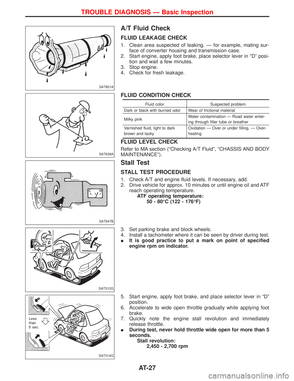
A/T Fluid Check
FLUID LEAKAGE CHECK
1. Clean area suspected of leaking. Ð for example, mating sur-
face of converter housing and transmission case.
2. Start engine, apply foot brake, place selector lever in ªDº posi-
tion and wait a few minutes.
3. Stop engine.
4. Check for fresh leakage.
FLUID CONDITION CHECK
Fluid color Suspected problem
Dark or black with burned odor Wear of frictional material
Milky pinkWater contamination Ð Road water enter-
ing through filler tube or breather
Varnished fluid, light to dark
brown and tackyOxidation Ð Over or under filling, Ð Over-
heating
FLUID LEVEL CHECK
Refer to MA section (ªChecking A/T Fluidº, ªCHASSIS AND BODY
MAINTENANCEº).
Stall Test
STALL TEST PROCEDURE
1. Check A/T and engine fluid levels. If necessary, add.
2. Drive vehicle for approx. 10 minutes or until engine oil and ATF
reach operating temperature.
ATF operating temperature:
50 - 80ÉC (122 - 176ÉF)
3. Set parking brake and block wheels.
4. Install a tachometer where it can be seen by driver during test.
IIt is good practice to put a mark on point of specified
engine rpm on indicator.
5. Start engine, apply foot brake, and place selector lever in ªDº
position.
6. Accelerate to wide open throttle gradually while applying foot
brake.
7. Quickly note the engine stall revolution and immediately
release throttle.
IDuring test, never hold throttle wide open for more than 5
seconds.
Stall revolution:
2,450 - 2,700 rpm
SAT801A
SAT638A
SAT647B
SAT513G
SAT514G
TROUBLE DIAGNOSIS Ð Basic Inspection
AT-27
Page 110 of 1767
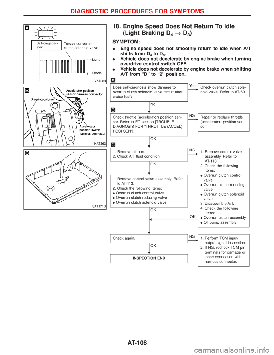
18. Engine Speed Does Not Return To Idle
(Light Braking D
4®D3)
SYMPTOM:
IEngine speed does not smoothly return to idle when A/T
shifts from D
4to D3.
IVehicle does not decelerate by engine brake when turning
overdrive control switch OFF.
IVehicle does not decelerate by engine brake when shifting
A/T from ªDº to ª2º position.
Does self-diagnosis show damage to
overrun clutch solenoid valve circuit after
cruise test?
No
EYe s
Check overrun clutch sole-
noid valve. Refer to AT-69.
Check throttle (accelerator) position sen-
sor. Refer to EC section [TROUBLE
DIAGNOSIS FOR ªTHROTTLE (ACCEL)
POSI SENº].
OK
ENG
Repair or replace throttle
(accelerator) position sen-
sor.
1. Remove oil pan.
2. Check A/T fluid condition.
OK
ENG
1. Remove control valve
assembly. Refer to
AT-113.
2. Check the following
items:
IOverrun clutch control
valve
IOverrun clutch reducing
valve
IOverrun clutch solenoid
valve
3. Disassemble A/T.
4. Check the following
items:
IOverrun clutch assembly
IOil pump assembly
1. Remove control valve assembly. Refer
to AT-113.
2. Check the following items:
IOverrun clutch control valve
IOverrun clutch reducing valve
IOverrun clutch solenoid valve
OK
FOK
Check again.
OK
ENG
1. Perform TCM input/
output signal inspection.
2. If NG, recheck TCM pin
terminals for damage or
loose connection with
harness connector.
INSPECTION END
YAT338
NAT262
SAT171B
H
H
H
H H
H
DIAGNOSTIC PROCEDURES FOR SYMPTOMS
AT-108
Page 114 of 1767
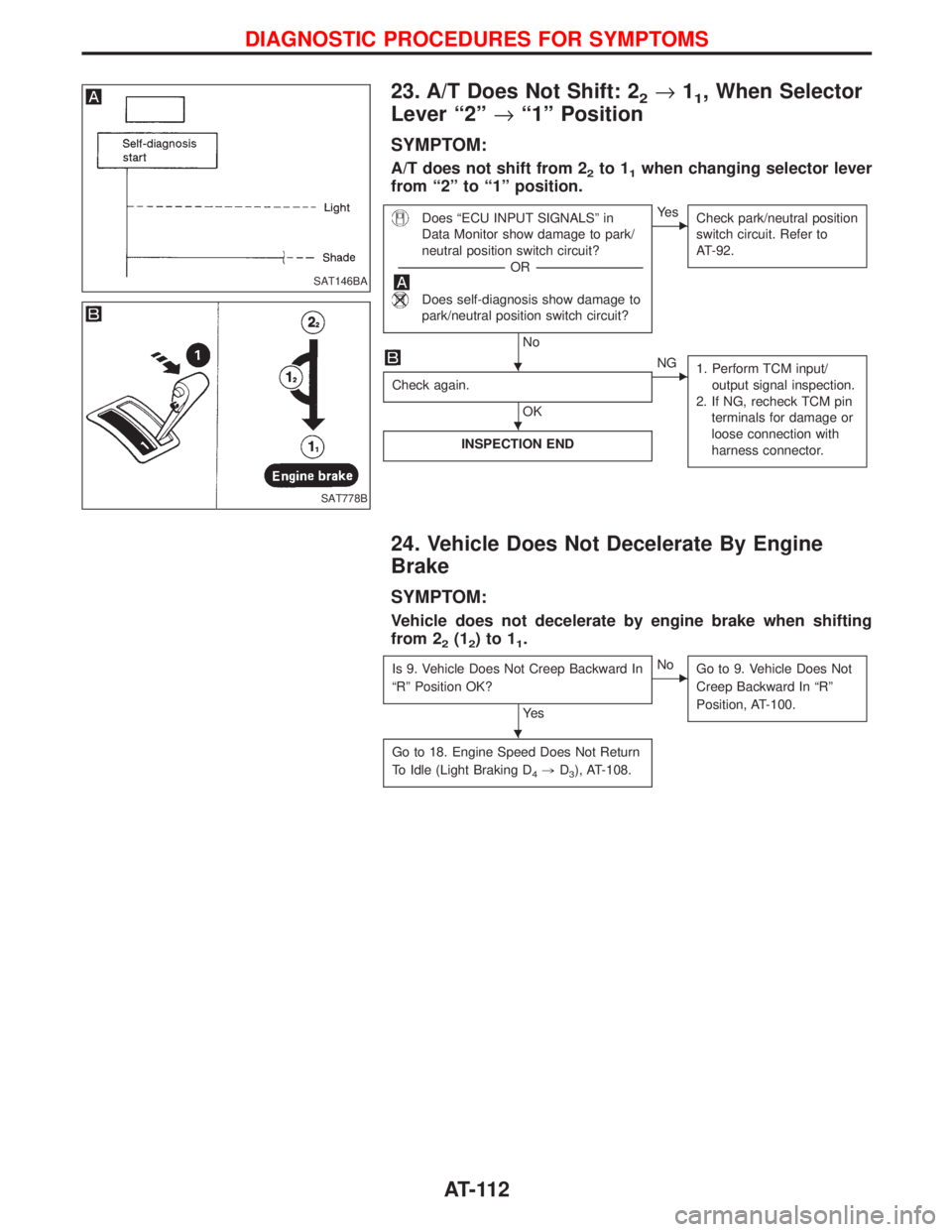
23. A/T Does Not Shift: 22®11, When Selector
Lever ª2º®ª1º Position
SYMPTOM:
A/T does not shift from 22to 11when changing selector lever
from ª2º to ª1º position.
Does ªECU INPUT SIGNALSº in
Data Monitor show damage to park/
neutral position switch circuit?
-----------------------------------------------------------------------------------------------------------------------OR -----------------------------------------------------------------------------------------------------------------------
Does self-diagnosis show damage to
park/neutral position switch circuit?
No
EYe s
Check park/neutral position
switch circuit. Refer to
AT-92.
Check again.
OK
ENG
1. Perform TCM input/
output signal inspection.
2. If NG, recheck TCM pin
terminals for damage or
loose connection with
harness connector.
INSPECTION END
24. Vehicle Does Not Decelerate By Engine
Brake
SYMPTOM:
Vehicle does not decelerate by engine brake when shifting
from 2
2(12)to11.
Is 9. Vehicle Does Not Creep Backward In
ªRº Position OK?
Ye s
ENo
Go to 9. Vehicle Does Not
Creep Backward In ªRº
Position, AT-100.
Go to 18. Engine Speed Does Not Return
To Idle (Light Braking D
4,D3), AT-108.
SAT146BA
SAT778B
H
H
H
DIAGNOSTIC PROCEDURES FOR SYMPTOMS
AT-112
Page 120 of 1767
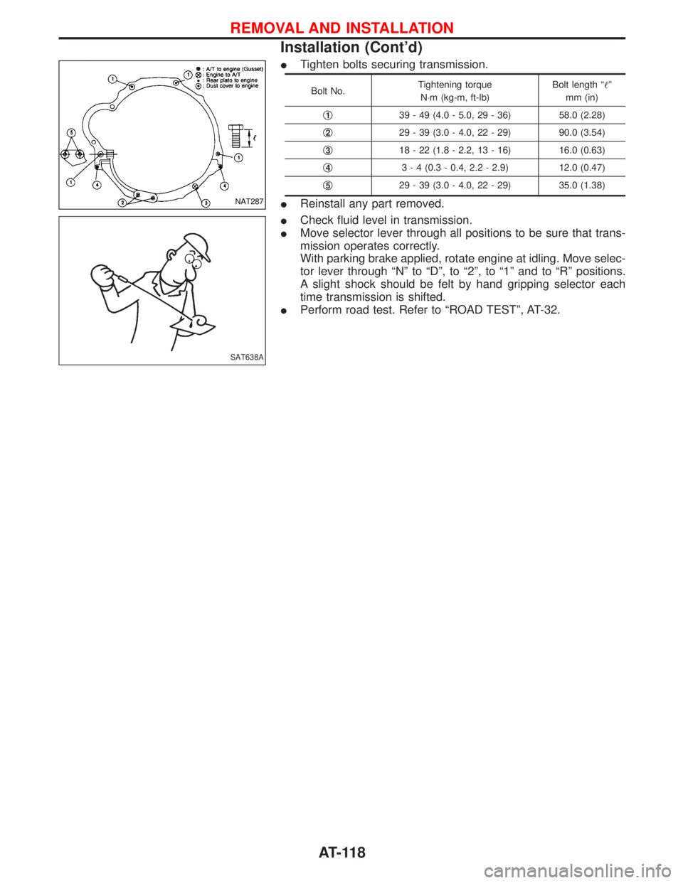
ITighten bolts securing transmission.
Bolt No.Tightening torque
N×m (kg-m, ft-lb)Bolt length ªº
mm (in)
q
139 - 49 (4.0 - 5.0, 29 - 36) 58.0 (2.28)
q
229 - 39 (3.0 - 4.0, 22 - 29) 90.0 (3.54)
q
318 - 22 (1.8 - 2.2, 13 - 16) 16.0 (0.63)
q
43 - 4 (0.3 - 0.4, 2.2 - 2.9) 12.0 (0.47)
q
529 - 39 (3.0 - 4.0, 22 - 29) 35.0 (1.38)
IReinstall any part removed.
ICheck fluid level in transmission.
IMove selector lever through all positions to be sure that trans-
mission operates correctly.
With parking brake applied, rotate engine at idling. Move selec-
tor lever through ªNº to ªDº, to ª2º, to ª1º and to ªRº positions.
A slight shock should be felt by hand gripping selector each
time transmission is shifted.
IPerform road test. Refer to ªROAD TESTº, AT-32.NAT287
SAT638A
REMOVAL AND INSTALLATION
Installation (Cont'd)
AT-118
Page 219 of 1767
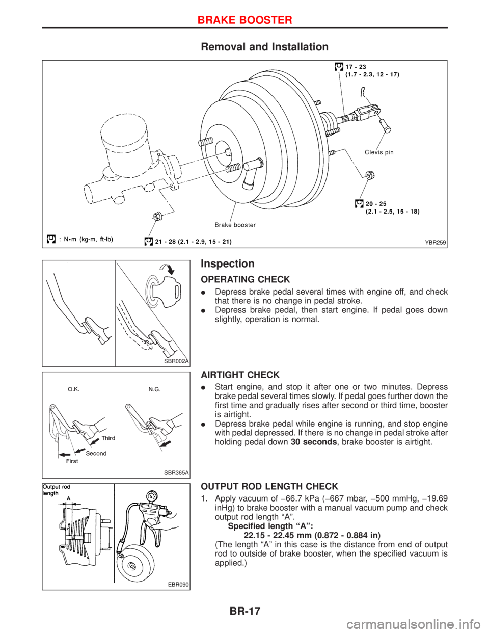
Removal and Installation
Inspection
OPERATING CHECK
IDepress brake pedal several times with engine off, and check
that there is no change in pedal stroke.
IDepress brake pedal, then start engine. If pedal goes down
slightly, operation is normal.
AIRTIGHT CHECK
IStart engine, and stop it after one or two minutes. Depress
brake pedal several times slowly. If pedal goes further down the
first time and gradually rises after second or third time, booster
is airtight.
IDepress brake pedal while engine is running, and stop engine
with pedal depressed. If there is no change in pedal stroke after
holding pedal down30 seconds, brake booster is airtight.
OUTPUT ROD LENGTH CHECK
1. Apply vacuum of þ66.7 kPa (þ667 mbar, þ500 mmHg, þ19.69
inHg) to brake booster with a manual vacuum pump and check
output rod length ªAº.
Specified length ªAº:
22.15 - 22.45 mm (0.872 - 0.884 in)
(The length ªAº in this case is the distance from end of output
rod to outside of brake booster, when the specified vacuum is
applied.)
YBR259
SBR002A
SBR365A
EBR090
BRAKE BOOSTER
BR-17
Page 226 of 1767
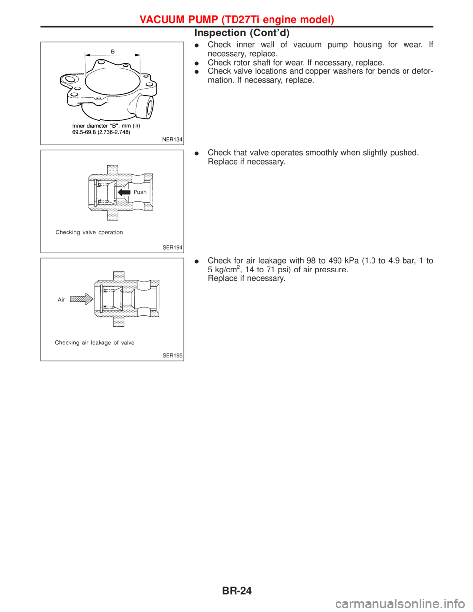
ICheck inner wall of vacuum pump housing for wear. If
necessary, replace.
ICheck rotor shaft for wear. If necessary, replace.
ICheck valve locations and copper washers for bends or defor-
mation. If necessary, replace.
ICheck that valve operates smoothly when slightly pushed.
Replace if necessary.
ICheck for air leakage with 98 to 490 kPa (1.0 to 4.9 bar, 1 to
5 kg/cm
2, 14 to 71 psi) of air pressure.
Replace if necessary.
NBR134
SBR194
SBR195
VACUUM PUMP (TD27Ti engine model)
Inspection (Cont'd)
BR-24