2002 NISSAN TERRANO tow
[x] Cancel search: towPage 6 of 1767
Supplemental Restraint System (SRS) ªAIR
BAGº and ªSEAT BELT PRE-TENSIONERº
The Supplemental Restraint System such as ªAIR BAGº and ªSEAT BELT PRE-TENSIONERº used along with
a seat belt, helps to reduce the risk or severity of injury to the driver and front passenger in a frontal collision.
The SRS system composition which is available to NISSAN MODEL R20 is as follows (The composition var-
ies according to the destination.):
Driver air bag module (located in the center of the steering wheel), front passenger air bag module (located
on the instrument panel on passenger side), seat belt pre-tensioner, a diagnosis sensor unit, warning lamp,
wiring harness and spiral cable.
Information necessary to service the system safely is included in theRS sectionof this Service Manual.
WARNING:
ITo avoid rendering the SRS inoperative, which could increase the risk of personal injury or death
in the event of a collision which would result in air bag inflation, all maintenance must be performed
by an authorized NISSAN dealer.
IImproper maintenance, including incorrect removal and installation of the SRS, can lead to per-
sonal injury caused by unintentional activation of the system. For removal of Spiral Cable and Air
Bag Module, see the RS section.
IDo not use electrical test equipment on any circuit related to the SRS unless instructed to in this
Service Manual. Spiral cable and wiring harnesses covered with yellow insulation either just before
the harness connectors or for the complete harness are related to the SRS.
Precautions
IBefore proceeding with disassembly, thoroughly clean the outside of the transmission. It is important to
prevent the internal parts from becoming contaminated by dirt or other foreign matter.
IDisassembly should be done in a clean work area.
IUse lint-free cloth or towels for wiping parts clean. Common shop rags can leave fibers that could inter-
fere with the operation of the transmission.
IPlace disassembled parts in order for easier and proper assembly.
IAll parts should be carefully cleaned with a general purpose, non-flammable solvent before inspection or
reassembly.
IGaskets, seals and O-rings should be replaced any time the transmission is disassembled.
IIt is very important to perform functional tests whenever they are indicated.
IThe valve body contains precision parts and requires extreme care when parts are removed and serviced.
Place removed parts in a parts rack in order to replace them in correct positions and sequences. Care will
also prevent springs and small parts from becoming scattered or lost.
IProperly installed valves, sleeves, plugs, etc. will slide along bores in valve body under their own weight.
IBefore assembly, apply a coat of recommended ATF to all parts. Apply petroleum jelly to protect O-rings
and seals, and to hold bearings and washers in place during assembly. Do not use grease.
IExtreme care should be taken to avoid damage to O-rings, seals and gaskets when assembling.
IAfter overhaul, refill the transmission with new ATF.
IWhen the A/T drain plug is removed, only some of the fluid is drained. Old A/T fluid will remain in torque
converter and ATF cooling system.
Always follow the procedures under ªChanging A/T Fluidº in the MA section when changing A/T fluid.
PREPARATION AND PRECAUTIONS
AT- 4
Page 117 of 1767
Manual Control Linkage Adjustment
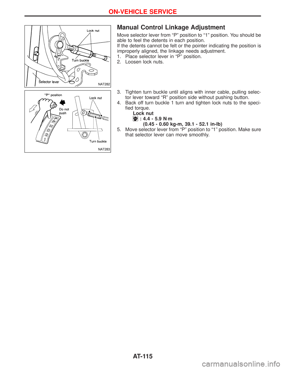
Move selector lever from ªPº position to ª1º position. You should be
able to feel the detents in each position.
If the detents cannot be felt or the pointer indicating the position is
improperly aligned, the linkage needs adjustment.
1. Place selector lever in ªPº position.
2. Loosen lock nuts.
3. Tighten turn buckle until aligns with inner cable, pulling selec-
tor lever toward ªRº position side without pushing button.
4. Back off turn buckle 1 turn and tighten lock nuts to the speci-
fied torque.
Lock nut
: 4.4 - 5.9 N×m
(0.45 - 0.60 kg-m, 39.1 - 52.1 in-lb)
5. Move selector lever from ªPº position to ª1º position. Make sure
that selector lever can move smoothly.
NAT282
NAT283
ON-VEHICLE SERVICE
AT-115
Page 138 of 1767
Side clearances
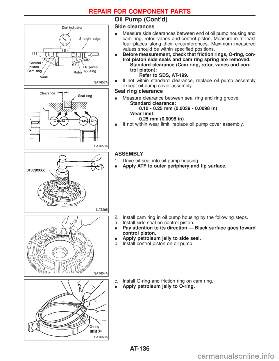
IMeasure side clearances between end of oil pump housing and
cam ring, rotor, vanes and control piston. Measure in at least
four places along their circumferences. Maximum measured
values should be within specified positions.
IBefore measurement, check that friction rings, O-ring, con-
trol piston side seals and cam ring spring are removed.
Standard clearance (Cam ring, rotor, vanes and con-
trol piston):
Refer to SDS, AT-199.
IIf not within standard clearance, replace oil pump assembly
except oil pump cover assembly.
Seal ring clearance
IMeasure clearance between seal ring and ring groove.
Standard clearance:
0.10 - 0.25 mm (0.0039 - 0.0098 in)
Wear limit:
0.25 mm (0.0098 in)
IIf not within wear limit, replace oil pump cover assembly.
ASSEMBLY
1. Drive oil seal into oil pump housing.
IApply ATF to outer periphery and lip surface.
2. Install cam ring in oil pump housing by the following steps.
a. Install side seal on control piston.
IPay attention to its direction Ð Black surface goes toward
control piston.
IApply petroleum jelly to side seal.
b. Install control piston on oil pump.
c. Install O-ring and friction ring on cam ring.
IApply petroleum jelly to O-ring.
SAT657A
SAT658A
NAT295
SAT654A
SAT660A
REPAIR FOR COMPONENT PARTS
Oil Pump (Cont'd)
AT-136
Page 293 of 1767
Checking Body Corrosion
Visually check the body sheet metal panel for corrosion, paint damage (scratches, chipping, rubbing, etc.) or
damage to the anti-corrosion materials. In particular, check the following locations.
Hemmed portion
Hood front end, door lower end, back door rear end, etc.
Panel joint
Side sill of rear fender and center pillar, rear wheel housing of rear fender, around strut tower in engine
compartment, etc.
Panel edge
Back door opening, sunroof opening, fender wheelarch flange, fuel filler lid flange, around holes in panel, etc.
Parts contact
Waist molding, windshield molding, bumper, etc.
Protectors
Damage or condition of mudguard, fender protector, chipping protector, etc.
Anti-corrosion materials
Damage or separation of anti-corrosion materials under the body.
Drain holes
Condition of drain holes at door and side sill.
When repairing corroded areas, refer to the Corrosion Repair Manual.
CHASSIS AND BODY MAINTENANCE
BT-5
Page 324 of 1767
Heated Seat
HFor Wiring Diagram, refer to EL-128, ªHEATED SEATº for details.
Active Head Restraint
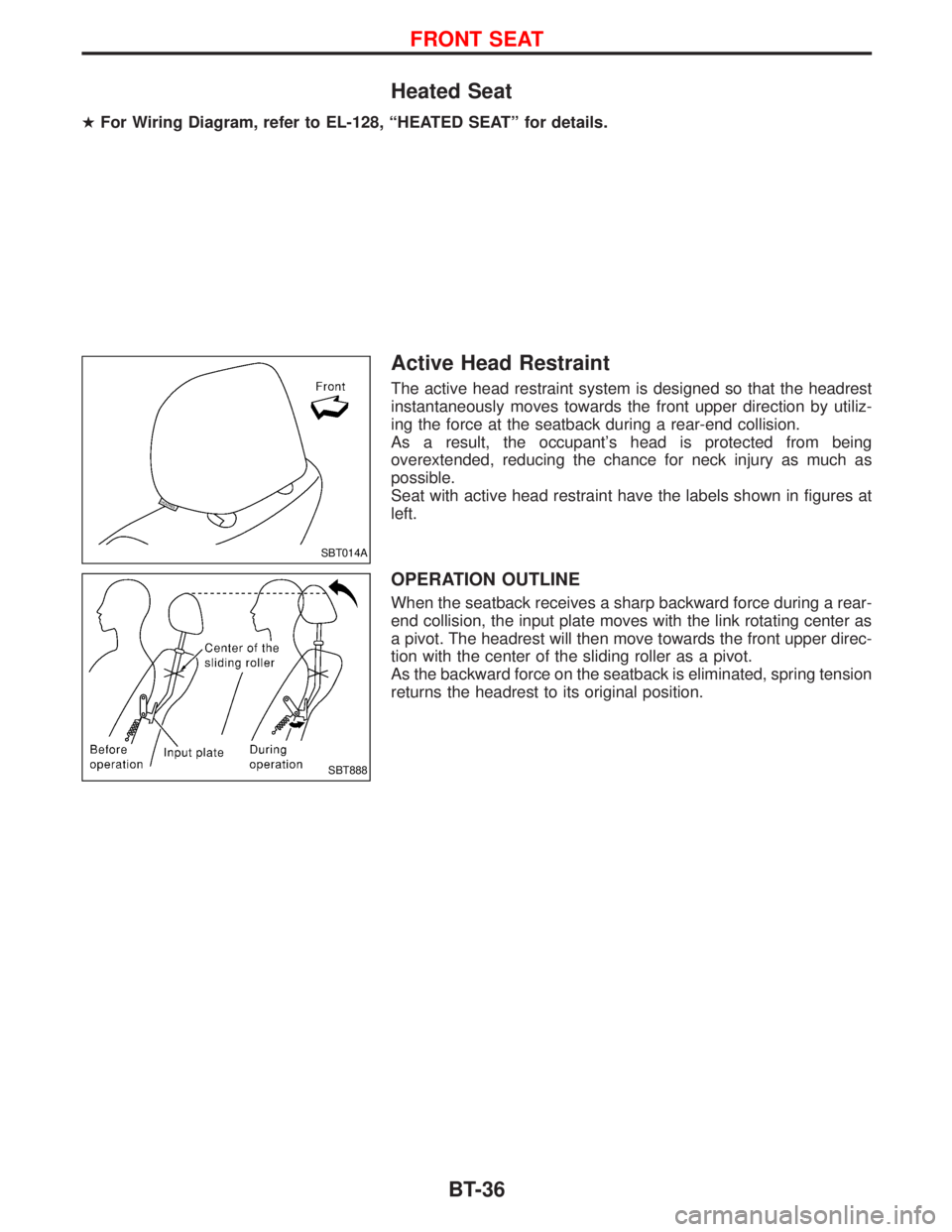
The active head restraint system is designed so that the headrest
instantaneously moves towards the front upper direction by utiliz-
ing the force at the seatback during a rear-end collision.
As a result, the occupant's head is protected from being
overextended, reducing the chance for neck injury as much as
possible.
Seat with active head restraint have the labels shown in figures at
left.
OPERATION OUTLINE
When the seatback receives a sharp backward force during a rear-
end collision, the input plate moves with the link rotating center as
a pivot. The headrest will then move towards the front upper direc-
tion with the center of the sliding roller as a pivot.
As the backward force on the seatback is eliminated, spring tension
returns the headrest to its original position.
SBT014A
SBT888
FRONT SEAT
BT-36
Page 392 of 1767
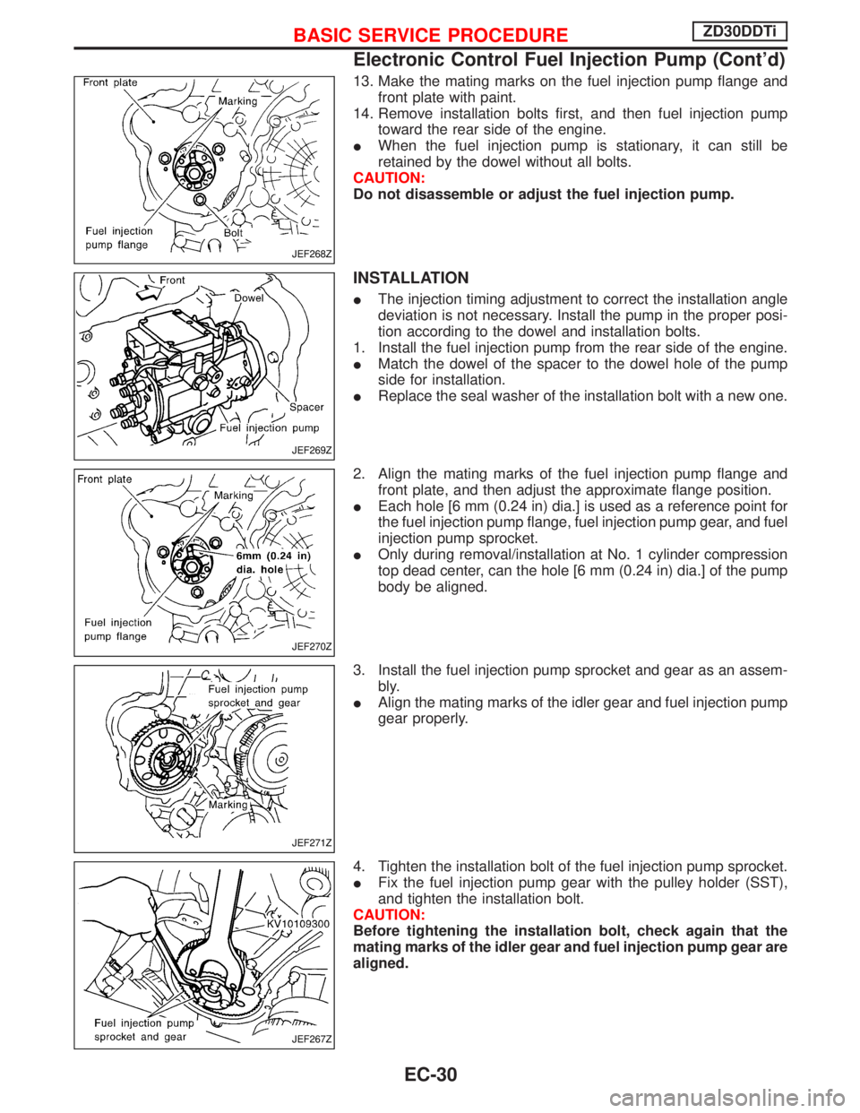
13. Make the mating marks on the fuel injection pump flange and
front plate with paint.
14. Remove installation bolts first, and then fuel injection pump
toward the rear side of the engine.
IWhen the fuel injection pump is stationary, it can still be
retained by the dowel without all bolts.
CAUTION:
Do not disassemble or adjust the fuel injection pump.
INSTALLATION
IThe injection timing adjustment to correct the installation angle
deviation is not necessary. Install the pump in the proper posi-
tion according to the dowel and installation bolts.
1. Install the fuel injection pump from the rear side of the engine.
IMatch the dowel of the spacer to the dowel hole of the pump
side for installation.
IReplace the seal washer of the installation bolt with a new one.
2. Align the mating marks of the fuel injection pump flange and
front plate, and then adjust the approximate flange position.
IEach hole [6 mm (0.24 in) dia.] is used as a reference point for
the fuel injection pump flange, fuel injection pump gear, and fuel
injection pump sprocket.
IOnly during removal/installation at No. 1 cylinder compression
top dead center, can the hole [6 mm (0.24 in) dia.] of the pump
body be aligned.
3. Install the fuel injection pump sprocket and gear as an assem-
bly.
IAlign the mating marks of the idler gear and fuel injection pump
gear properly.
4. Tighten the installation bolt of the fuel injection pump sprocket.
IFix the fuel injection pump gear with the pulley holder (SST),
and tighten the installation bolt.
CAUTION:
Before tightening the installation bolt, check again that the
mating marks of the idler gear and fuel injection pump gear are
aligned.
JEF268Z
JEF269Z
JEF270Z
JEF271Z
JEF267Z
BASIC SERVICE PROCEDUREZD30DDTi
Electronic Control Fuel Injection Pump (Cont'd)
EC-30
Page 677 of 1767
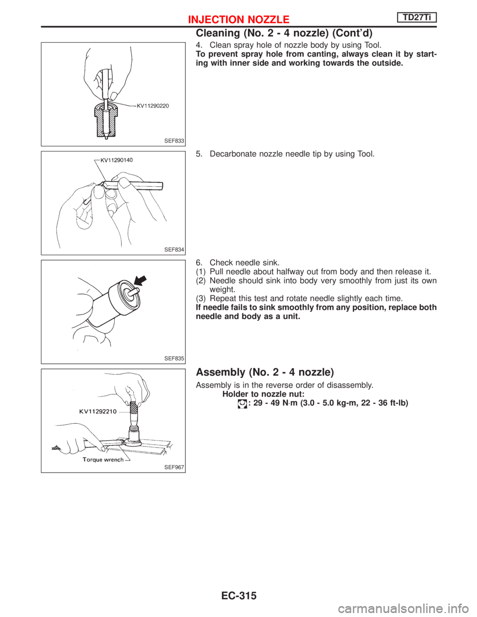
4. Clean spray hole of nozzle body by using Tool.
To prevent spray hole from canting, always clean it by start-
ing with inner side and working towards the outside.
5. Decarbonate nozzle needle tip by using Tool.
6. Check needle sink.
(1) Pull needle about halfway out from body and then release it.
(2) Needle should sink into body very smoothly from just its own
weight.
(3) Repeat this test and rotate needle slightly each time.
If needle fails to sink smoothly from any position, replace both
needle and body as a unit.
Assembly (No.2-4nozzle)
Assembly is in the reverse order of disassembly.
Holder to nozzle nut:
:29-49N×m (3.0 - 5.0 kg-m, 22 - 36 ft-lb)
SEF833
SEF834
SEF835
SEF967
INJECTION NOZZLETD27Ti
Cleaning (No.2-4nozzle) (Cont'd)
EC-315
Page 697 of 1767
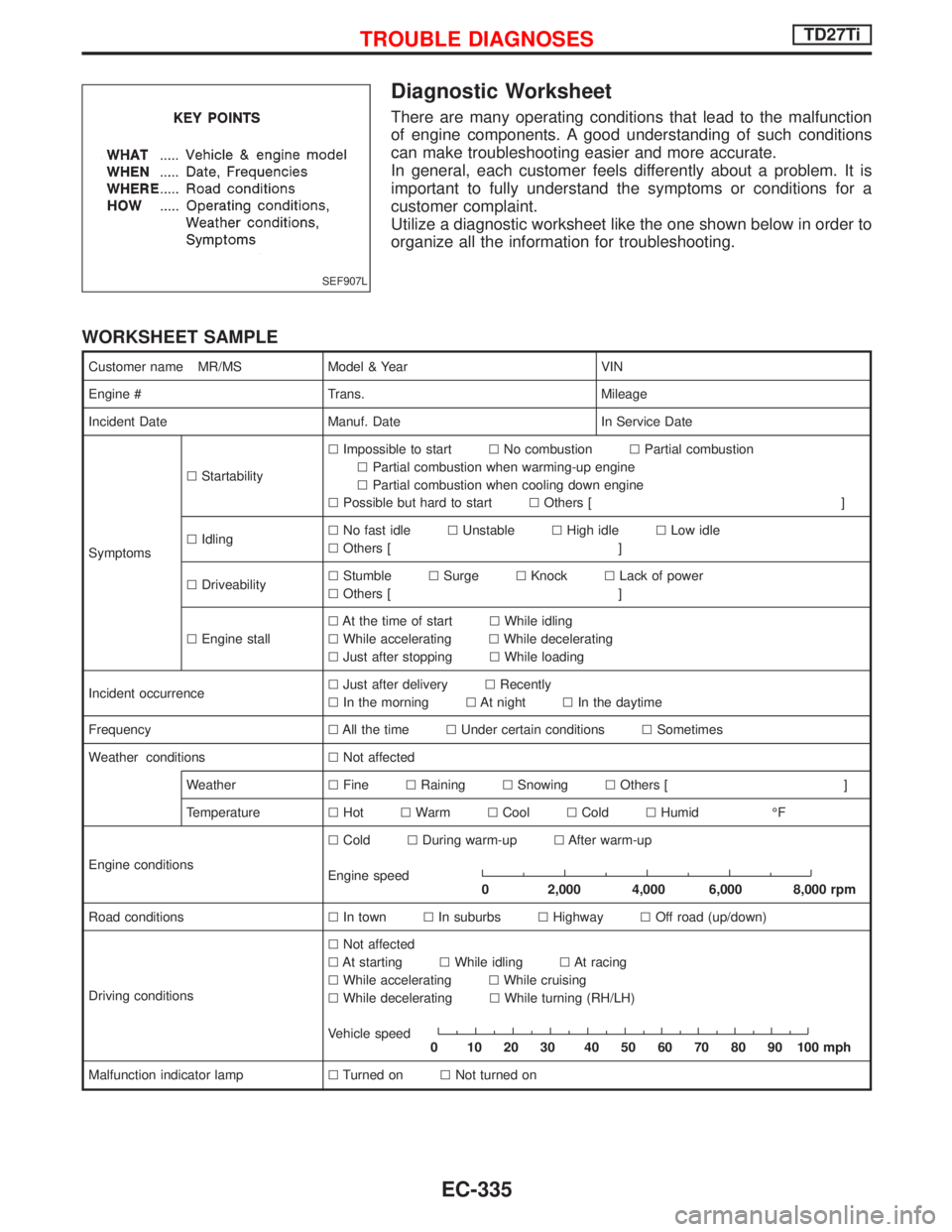
Diagnostic Worksheet
There are many operating conditions that lead to the malfunction
of engine components. A good understanding of such conditions
can make troubleshooting easier and more accurate.
In general, each customer feels differently about a problem. It is
important to fully understand the symptoms or conditions for a
customer complaint.
Utilize a diagnostic worksheet like the one shown below in order to
organize all the information for troubleshooting.
WORKSHEET SAMPLE
Customer name MR/MS Model & Year VIN
Engine # Trans. Mileage
Incident Date Manuf. Date In Service Date
SymptomslStartabilitylImpossible to startlNo combustionlPartial combustion
lPartial combustion when warming-up engine
lPartial combustion when cooling down engine
lPossible but hard to startlOthers [ ]
lIdlinglNo fast idlelUnstablelHigh idlelLow idle
lOthers [ ]
lDriveabilitylStumblelSurgelKnocklLack of power
lOthers [ ]
lEngine stalllAt the time of startlWhile idling
lWhile acceleratinglWhile decelerating
lJust after stoppinglWhile loading
Incident occurrencelJust after deliverylRecently
lIn the morninglAt nightlIn the daytime
FrequencylAll the timelUnder certain conditionslSometimes
Weather conditionslNot affected
WeatherlFinelRaininglSnowinglOthers [ ]
TemperaturelHotlWarmlCoollColdlHumid ÉF
Engine conditionslColdlDuring warm-uplAfter warm-up
Engine speed
0 2,000 4,000 6,000 8,000 rpm
Road conditionslIn townlIn suburbslHighwaylOff road (up/down)
Driving conditionslNot affected
lAt startinglWhile idlinglAt racing
lWhile acceleratinglWhile cruising
lWhile deceleratinglWhile turning (RH/LH)
Vehicle speed
0 102030 405060708090100mph
Malfunction indicator lamplTurned onlNot turned on
SEF907L
TROUBLE DIAGNOSESTD27Ti
EC-335