2002 NISSAN TERRANO fuse chart
[x] Cancel search: fuse chartPage 993 of 1767
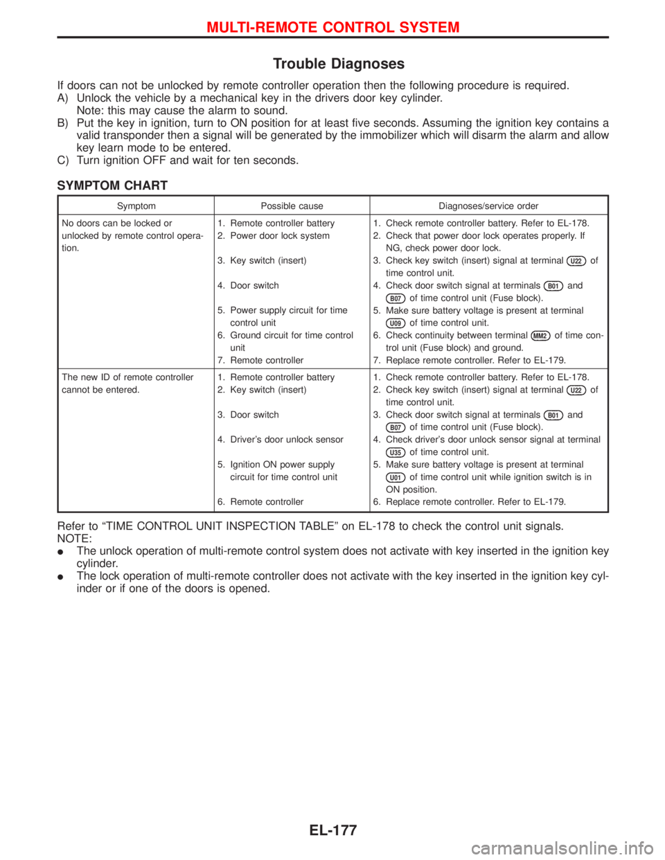
Trouble Diagnoses
If doors can not be unlocked by remote controller operation then the following procedure is required.
A) Unlock the vehicle by a mechanical key in the drivers door key cylinder.
Note: this may cause the alarm to sound.
B) Put the key in ignition, turn to ON position for at least five seconds. Assuming the ignition key contains a
valid transponder then a signal will be generated by the immobilizer which will disarm the alarm and allow
key learn mode to be entered.
C) Turn ignition OFF and wait for ten seconds.
SYMPTOM CHART
Symptom Possible cause Diagnoses/service order
No doors can be locked or
unlocked by remote control opera-
tion.1. Remote controller battery
2. Power door lock system
3. Key switch (insert)
4. Door switch
5. Power supply circuit for time
control unit
6. Ground circuit for time control
unit
7. Remote controller1. Check remote controller battery. Refer to EL-178.
2. Check that power door lock operates properly. If
NG, check power door lock.
3. Check key switch (insert) signal at terminal
U22of
time control unit.
4. Check door switch signal at terminals
B01and
B07of time control unit (Fuse block).
5. Make sure battery voltage is present at terminal
U09of time control unit.
6. Check continuity between terminal
MM2of time con-
trol unit (Fuse block) and ground.
7. Replace remote controller. Refer to EL-179.
The new ID of remote controller
cannot be entered.1. Remote controller battery
2. Key switch (insert)
3. Door switch
4. Driver's door unlock sensor
5. Ignition ON power supply
circuit for time control unit
6. Remote controller1. Check remote controller battery. Refer to EL-178.
2. Check key switch (insert) signal at terminal
U22of
time control unit.
3. Check door switch signal at terminals
B01and
B07of time control unit (Fuse block).
4. Check driver's door unlock sensor signal at terminal
U35of time control unit.
5. Make sure battery voltage is present at terminal
U01of time control unit while ignition switch is in
ON position.
6. Replace remote controller. Refer to EL-179.
Refer to ªTIME CONTROL UNIT INSPECTION TABLEº on EL-178 to check the control unit signals.
NOTE:
IThe unlock operation of multi-remote control system does not activate with key inserted in the ignition key
cylinder.
IThe lock operation of multi-remote controller does not activate with the key inserted in the ignition key cyl-
inder or if one of the doors is opened.
MULTI-REMOTE CONTROL SYSTEM
EL-177
Page 1013 of 1767
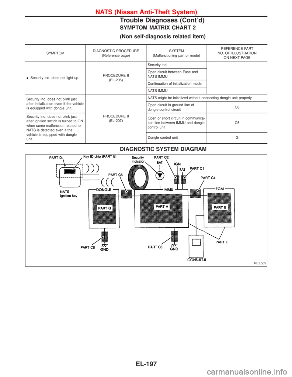
SYMPTOM MATRIX CHART 2
(Non self-diagnosis related item)
SYMPTOMDIAGNOSTIC PROCEDURE
(Reference page)SYSTEM
(Malfunctioning part or mode)REFERENCE PART
NO. OF ILLUSTRATION
ON NEXT PAGE
ISecurity ind. does not light up.PROCEDURE 6
(EL-205)Security ind.
Open circuit between Fuse and
NATS IMMU
Continuation of initialization mode
NATS IMMU
Security ind. does not blink just
after initialization even if the vehicle
is equipped with dongle unit.
PROCEDURE 8
(EL-207)NATS might be initialized without connecting dongle unit properly.
Open circuit in ground line of
dongle control circuitC6
Security ind. does not blink just
after ignition switch is turned to ON
when some malfunction related to
NATS is detected even if the
vehicle is equipped with dongle
unit.Open or short circuit in communica-
tion line between IMMU and dongle
control unitC5
Dongle control unit G
DIAGNOSTIC SYSTEM DIAGRAM
NEL559
NATS (Nissan Anti-Theft System)
Trouble Diagnoses (Cont'd)
EL-197
Page 1328 of 1767
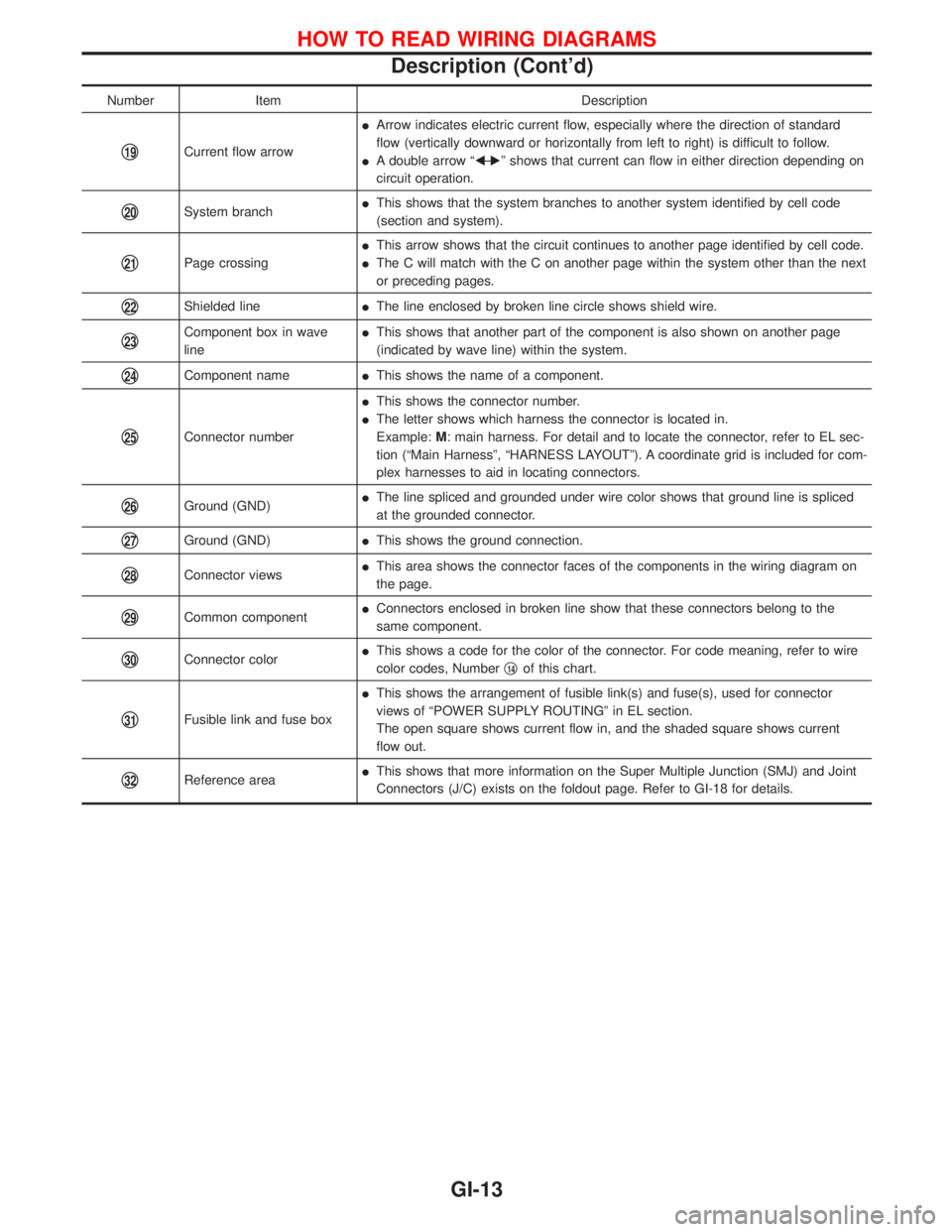
Number Item Description
q19Current flow arrowIArrow indicates electric current flow, especially where the direction of standard
flow (vertically downward or horizontally from left to right) is difficult to follow.
IA double arrow ªFÐ
Eº shows that current can flow in either direction depending on
circuit operation.
q20System branchIThis shows that the system branches to another system identified by cell code
(section and system).
q21Page crossingIThis arrow shows that the circuit continues to another page identified by cell code.
IThe C will match with the C on another page within the system other than the next
or preceding pages.
q22Shielded lineIThe line enclosed by broken line circle shows shield wire.
q23Component box in wave
lineIThis shows that another part of the component is also shown on another page
(indicated by wave line) within the system.
q24Component nameIThis shows the name of a component.
q25Connector numberIThis shows the connector number.
IThe letter shows which harness the connector is located in.
Example:M: main harness. For detail and to locate the connector, refer to EL sec-
tion (ªMain Harnessº, ªHARNESS LAYOUTº). A coordinate grid is included for com-
plex harnesses to aid in locating connectors.
q26Ground (GND)IThe line spliced and grounded under wire color shows that ground line is spliced
at the grounded connector.
q27Ground (GND)IThis shows the ground connection.
q28Connector viewsIThis area shows the connector faces of the components in the wiring diagram on
the page.
q29Common componentIConnectors enclosed in broken line show that these connectors belong to the
same component.
q30Connector colorIThis shows a code for the color of the connector. For code meaning, refer to wire
color codes, Numberq14of this chart.
q31Fusible link and fuse boxIThis shows the arrangement of fusible link(s) and fuse(s), used for connector
views of ªPOWER SUPPLY ROUTINGº in EL section.
The open square shows current flow in, and the shaded square shows current
flow out.
q32Reference areaIThis shows that more information on the Super Multiple Junction (SMJ) and Joint
Connectors (J/C) exists on the foldout page. Refer to GI-18 for details.
HOW TO READ WIRING DIAGRAMS
Description (Cont'd)
GI-13
Page 1389 of 1767
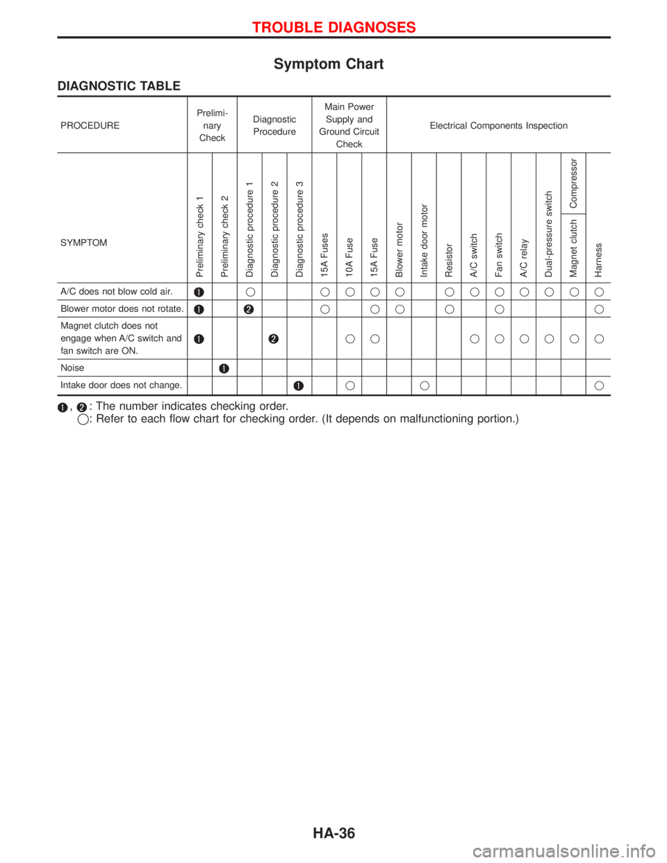
Symptom Chart
DIAGNOSTIC TABLE
PROCEDUREPrelimi-
nary
CheckDiagnostic
ProcedureMain Power
Supply and
Ground Circuit
CheckElectrical Components Inspection
SYMPTOM
Preliminary check 1
Preliminary check 2
Diagnostic procedure 1
Diagnostic procedure 2
Diagnostic procedure 3
15A Fuses
10A Fuse
15A Fuse
Blower motor
Intake door motor
Resistor
A/C switch
Fan switch
A/C relay
Dual-pressure switch
Compressor
Harness Magnet clutch
A/C does not blow cold air.q qqqq qqqqqqq
Blower motor does not rotate.
qqqqq q
Magnet clutch does not
engage when A/C switch and
fan switch are ON.
qq qqqqqq
Noise
Intake door does not change.qq q
,: The number indicates checking order.
q: Refer to each flow chart for checking order. (It depends on malfunctioning portion.)
TROUBLE DIAGNOSES
HA-36
Page 1405 of 1767
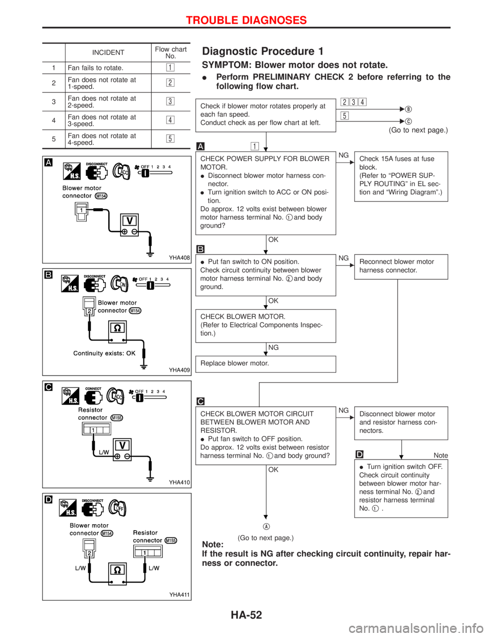
Diagnostic Procedure 1
SYMPTOM: Blower motor does not rotate.
IPerform PRELIMINARY CHECK 2 before referring to the
following flow chart.
Check if blower motor rotates properly at
each fan speed.
Conduct check as per flow chart at left.234EqB5EqC
(Go to next page.)
1
CHECK POWER SUPPLY FOR BLOWER
MOTOR.
IDisconnect blower motor harness con-
nector.
ITurn ignition switch to ACC or ON posi-
tion.
Do approx. 12 volts exist between blower
motor harness terminal No.q
1and body
ground?
OK
ENG
Check 15A fuses at fuse
block.
(Refer to ªPOWER SUP-
PLY ROUTINGº in EL sec-
tion and ªWiring Diagramº.)
IPut fan switch to ON position.
Check circuit continuity between blower
motor harness terminal No.q
2and body
ground.
OK
ENG
Reconnect blower motor
harness connector.
CHECK BLOWER MOTOR.
(Refer to Electrical Components Inspec-
tion.)
NG
Replace blower motor.
CHECK BLOWER MOTOR CIRCUIT
BETWEEN BLOWER MOTOR AND
RESISTOR.
IPut fan switch to OFF position.
Do approx. 12 volts exist between resistor
harness terminal No.q
1and body ground?
OK
ENG
Disconnect blower motor
and resistor harness con-
nectors.
Note
ITurn ignition switch OFF.
Check circuit continuity
between blower motor har-
ness terminal No.q
2and
resistor harness terminal
No.q
1.
qA
(Go to next page.)Note:
If the result is NG after checking circuit continuity, repair har-
ness or connector.
INCIDENTFlow chart
No.
1 Fan fails to rotate.
1
2Fan does not rotate at
1-speed.2
3Fan does not rotate at
2-speed.3
4Fan does not rotate at
3-speed.4
5Fan does not rotate at
4-speed.5
YHA408
YHA409
YHA410
YHA411
H
H
H
H
H
H
TROUBLE DIAGNOSES
HA-52
Page 1657 of 1767
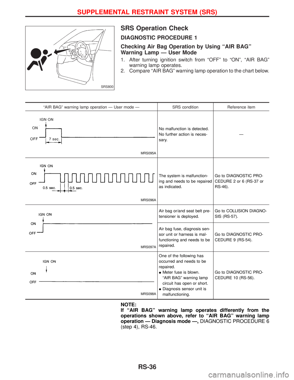
SRS Operation Check
DIAGNOSTIC PROCEDURE 1
Checking Air Bag Operation by Using ªAIR BAGº
Warning Lamp Ð User Mode
1. After turning ignition switch from ªOFFº to ªONº, ªAIR BAGº
warning lamp operates.
2. Compare ªAIR BAGº warning lamp operation to the chart below.
ªAIR BAGº warning lamp operation Ð User mode Ð SRS condition Reference item
MRS095A
No malfunction is detected.
No further action is neces-
sary.Ð
MRS096A
The system is malfunction-
ing and needs to be repaired
as indicated.Go to DIAGNOSTIC PRO-
CEDURE 2 or 6 (RS-37 or
RS-46).
MRS097A
Air bag or/and seat belt pre-
tensioner is deployed.Go to COLLISION DIAGNO-
SIS (RS-57).
Air bag fuse, diagnosis sen-
sor unit or harness is mal-
functioning and needs to be
repaired.Go to DIAGNOSTIC PRO-
CEDURE 9 (RS-54).
MRS098A
One of the following has
occurred and needs to be
repaired.
IMeter fuse is blown.
ªAIR BAGº warning lamp
circuit has open or short.
IDiagnosis sensor unit is
malfunctioning.Go to DIAGNOSTIC PRO-
CEDURE 10 (RS-56).
NOTE:
If ªAIR BAGº warning lamp operates differently from the
operations shown above, refer to ªAIR BAGº warning lamp
operation Ð Diagnosis mode Ð,DIAGNOSTIC PROCEDURE 6
(step 4), RS-46.
SRS800
SUPPLEMENTAL RESTRAINT SYSTEM (SRS)
RS-36