2002 NISSAN TERRANO differential
[x] Cancel search: differentialPage 1 of 1767

Edition: February 2002
Release: February 2002 (01)
Publication No.: SM2E00-1R20E0E
GENERAL INFORMATIONGI
MAINTENANCEMA
ENGINE MECHANICALEM
ENGINE LUBRICATION &
COOLING SYSTEMSLC
ENGINE CONTROL SYSTEMEC
ACCELERATOR CONTROL,
FUEL & EXHAUST SYSTEMFE
CLUTCHCL
MANUAL TRANSMISSIONMT
AUTOMATIC TRANSMISSIONAT
TRANSFERTF
PROPELLER SHAFT &
DIFFERENTIAL CARRIERPD
FRONT AXLE & FRONT SUSPENSIONFA
REAR AXLE & REAR SUSPENSIONRA
BRAKE SYSTEMBR
STEERING SYSTEMST
RESTRAINT SYSTEMRS
BODY & TRIMBT
HEATER & AIR CONDITIONERHA
STARTING & CHARGING SYSTEMSSC
ELECTRICAL SYSTEMEL
ALPHABETICAL INDEXIDX
TERRANO
MODEL R20 SERIES
NISSAN EUROPE N.V.
NISSAN EUROPE N.V.
Produced in The Netherlands
QUICK REFERENCE INDEX
Page 1130 of 1767
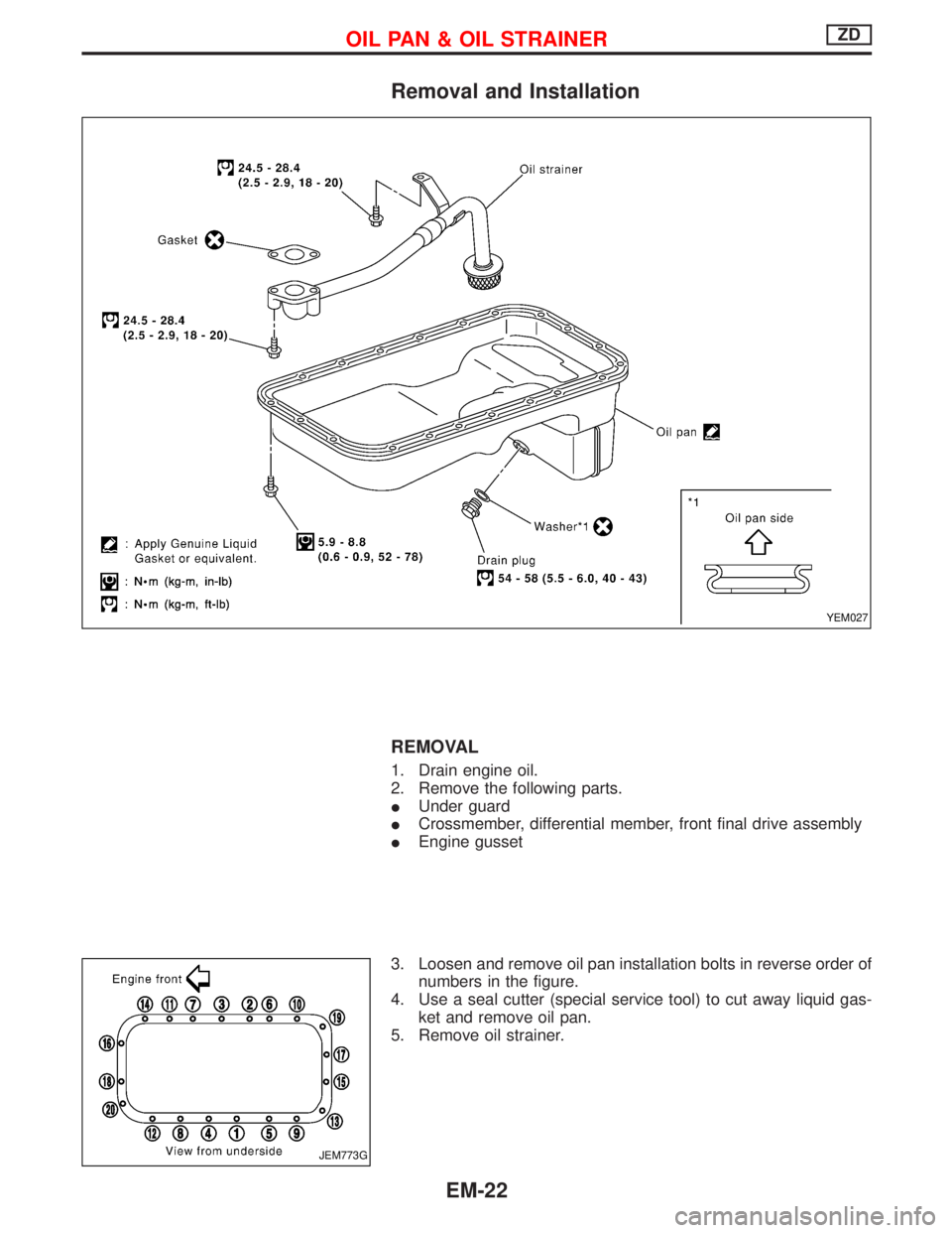
Removal and Installation
REMOVAL
1. Drain engine oil.
2. Remove the following parts.
IUnder guard
ICrossmember, differential member, front final drive assembly
IEngine gusset
3. Loosen and remove oil pan installation bolts in reverse order of
numbers in the figure.
4. Use a seal cutter (special service tool) to cut away liquid gas-
ket and remove oil pan.
5. Remove oil strainer.
YEM027
JEM773G
OIL PAN & OIL STRAINERZD
EM-22
Page 1192 of 1767
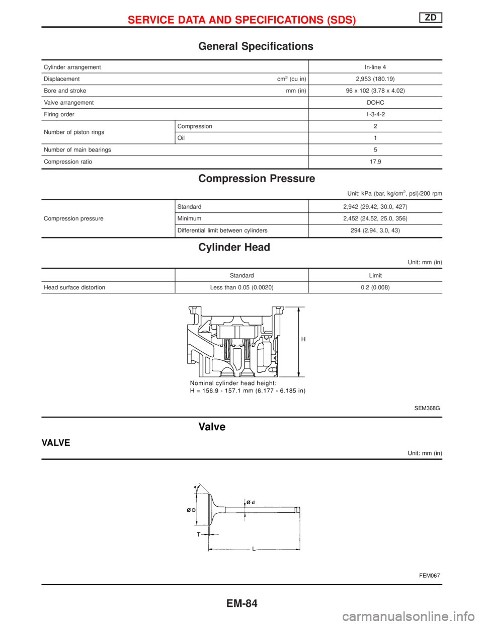
General Specifications
Cylinder arrangementIn-line 4
Displacementcm
3(cu in) 2,953 (180.19)
Bore and strokemm (in) 96 x 102 (3.78 x 4.02)
Valve arrangementDOHC
Firing order1-3-4-2
Number of piston ringsCompression 2
Oil1
Number of main bearings5
Compression ratio17.9
Compression Pressure
Unit: kPa (bar, kg/cm2, psi)/200 rpm
Compression pressureStandard 2,942 (29.42, 30.0, 427)
Minimum 2,452 (24.52, 25.0, 356)
Differential limit between cylinders 294 (2.94, 3.0, 43)
Cylinder Head
Unit: mm (in)
Standard Limit
Head surface distortion Less than 0.05 (0.0020) 0.2 (0.008)
SEM368G
Valve
VA LV E
Unit: mm (in)
FEM067
SERVICE DATA AND SPECIFICATIONS (SDS)ZD
EM-84
Page 1211 of 1767
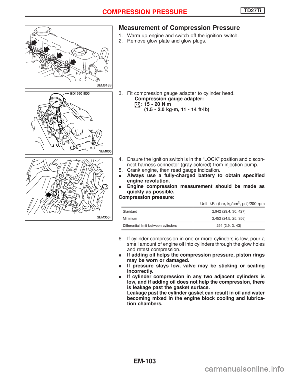
Measurement of Compression Pressure
1. Warm up engine and switch off the ignition switch.
2. Remove glow plate and glow plugs.
3. Fit compression gauge adapter to cylinder head.
Compression gauge adapter:
:15-20N×m
(1.5 - 2.0 kg-m, 11 - 14 ft-lb)
4. Ensure the ignition switch is in the ªLOCKº position and discon-
nect harness connector (gray colored) from injection pump.
5. Crank engine, then read gauge indication.
IAlways use a fully-charged battery to obtain specified
engine revolution.
IEngine compression measurement should be made as
quickly as possible.
Compression pressure:
Unit: kPa (bar, kg/cm2, psi)/200 rpm
Standard 2,942 (29.4, 30, 427)
Minimum 2,452 (24.5, 25, 356)
Differential limit between cylinders 294 (2.9, 3, 43)
6. If cylinder compression in one or more cylinders is low, pour a
small amount of engine oil into cylinders through the glow holes
and retest compression.
IIf adding oil helps the compression pressure, piston rings
may be worn or damaged.
IIf pressure stays low, valve may be sticking or seating
incorrectly.
IIf cylinder compression in any two adjacent cylinders is
low, and if adding oil does not help the compression, there
is leakage past the gasket surface.
Leakage past the cylinder gasket can result in oil and water
becoming mixed in the engine block cooling and lubrica-
tion chambers.
SEM618B
NEM005
SEM355F
COMPRESSION PRESSURETD27Ti
EM-103
Page 1251 of 1767
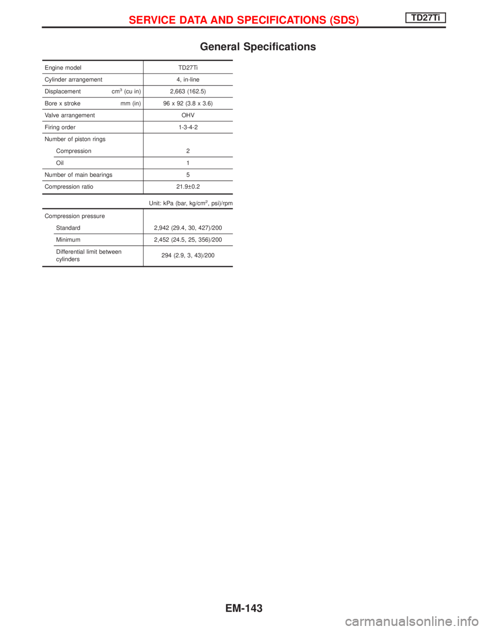
General Specifications
Engine model TD27Ti
Cylinder arrangement 4, in-line
Displacement cm
3(cu in) 2,663 (162.5)
Bore x stroke mm (in) 96 x 92 (3.8 x 3.6)
Valve arrangement OHV
Firing order 1-3-4-2
Number of piston rings
Compression 2
Oil 1
Number of main bearings 5
Compression ratio 21.9 0.2
Unit: kPa (bar, kg/cm
2, psi)/rpm
Compression pressure
Standard 2,942 (29.4, 30, 427)/200
Minimum 2,452 (24.5, 25, 356)/200
Differential limit between
cylinders294 (2.9, 3, 43)/200
SERVICE DATA AND SPECIFICATIONS (SDS)TD27Ti
EM-143
Page 1275 of 1767
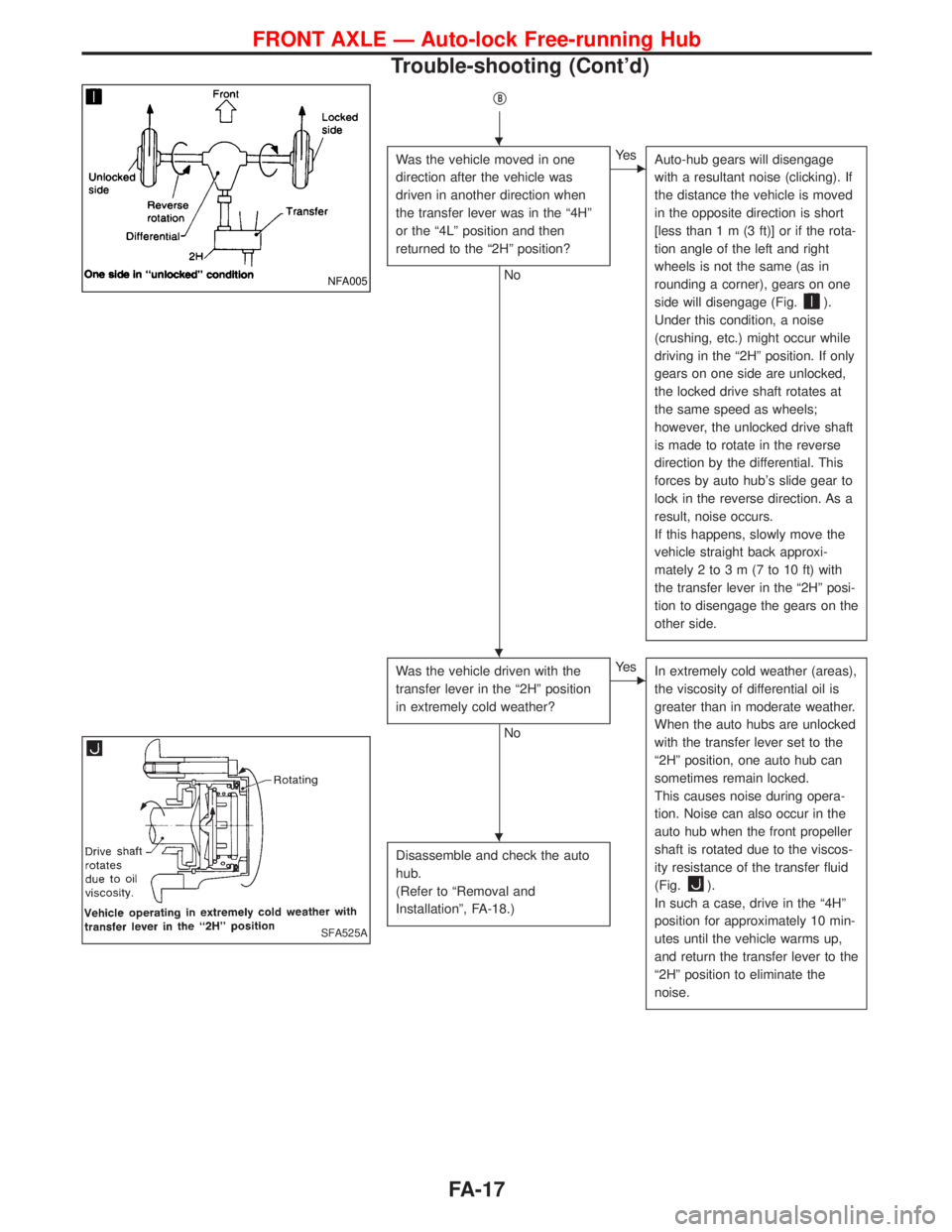
qB
Was the vehicle moved in one
direction after the vehicle was
driven in another direction when
the transfer lever was in the ª4Hº
or the ª4Lº position and then
returned to the ª2Hº position?
No
EYe s
Auto-hub gears will disengage
with a resultant noise (clicking). If
the distance the vehicle is moved
in the opposite direction is short
[less than1m(3ft)] or if the rota-
tion angle of the left and right
wheels is not the same (as in
rounding a corner), gears on one
side will disengage (Fig.
).
Under this condition, a noise
(crushing, etc.) might occur while
driving in the ª2Hº position. If only
gears on one side are unlocked,
the locked drive shaft rotates at
the same speed as wheels;
however, the unlocked drive shaft
is made to rotate in the reverse
direction by the differential. This
forces by auto hub's slide gear to
lock in the reverse direction. As a
result, noise occurs.
If this happens, slowly move the
vehicle straight back approxi-
mately 2 to3m(7to10ft)with
the transfer lever in the ª2Hº posi-
tion to disengage the gears on the
other side.
Was the vehicle driven with the
transfer lever in the ª2Hº position
in extremely cold weather?
No
EYe s
In extremely cold weather (areas),
the viscosity of differential oil is
greater than in moderate weather.
When the auto hubs are unlocked
with the transfer lever set to the
ª2Hº position, one auto hub can
sometimes remain locked.
This causes noise during opera-
tion. Noise can also occur in the
auto hub when the front propeller
shaft is rotated due to the viscos-
ity resistance of the transfer fluid
(Fig.
).
In such a case, drive in the ª4Hº
position for approximately 10 min-
utes until the vehicle warms up,
and return the transfer lever to the
ª2Hº position to eliminate the
noise.
Disassemble and check the auto
hub.
(Refer to ªRemoval and
Installationº, FA-18.)
NFA005
SFA525A
H
H
H
FRONT AXLE Ð Auto-lock Free-running Hub
Trouble-shooting (Cont'd)
FA-17
Page 1351 of 1767
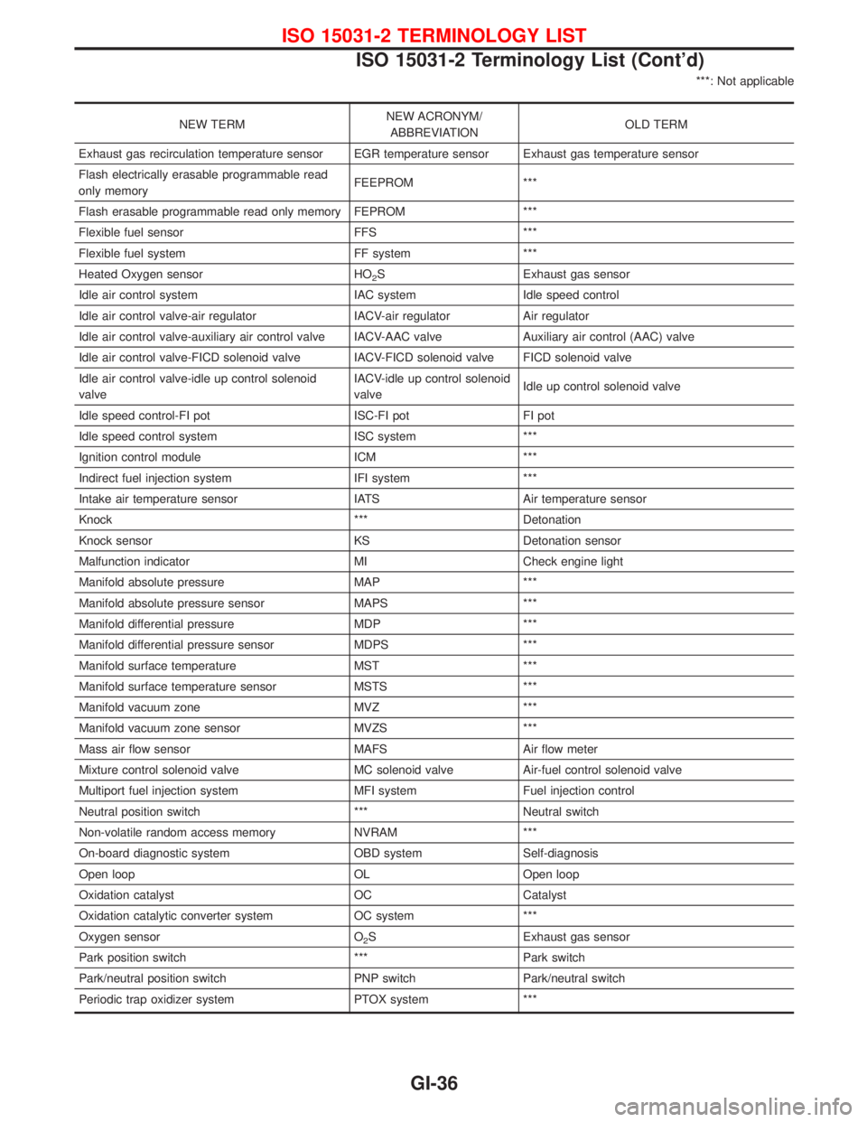
***: Not applicable
NEW TERMNEW ACRONYM/
ABBREVIATIONOLD TERM
Exhaust gas recirculation temperature sensor EGR temperature sensor Exhaust gas temperature sensor
Flash electrically erasable programmable read
only memoryFEEPROM ***
Flash erasable programmable read only memory FEPROM ***
Flexible fuel sensor FFS ***
Flexible fuel system FF system ***
Heated Oxygen sensor HO
2S Exhaust gas sensor
Idle air control system IAC system Idle speed control
Idle air control valve-air regulator IACV-air regulator Air regulator
Idle air control valve-auxiliary air control valve IACV-AAC valve Auxiliary air control (AAC) valve
Idle air control valve-FICD solenoid valve IACV-FICD solenoid valve FICD solenoid valve
Idle air control valve-idle up control solenoid
valveIACV-idle up control solenoid
valveIdle up control solenoid valve
Idle speed control-FI pot ISC-FI pot FI pot
Idle speed control system ISC system ***
Ignition control module ICM ***
Indirect fuel injection system IFI system ***
Intake air temperature sensor IATS Air temperature sensor
Knock *** Detonation
Knock sensor KS Detonation sensor
Malfunction indicator MI Check engine light
Manifold absolute pressure MAP ***
Manifold absolute pressure sensor MAPS ***
Manifold differential pressure MDP ***
Manifold differential pressure sensor MDPS ***
Manifold surface temperature MST ***
Manifold surface temperature sensor MSTS ***
Manifold vacuum zone MVZ ***
Manifold vacuum zone sensor MVZS ***
Mass air flow sensor MAFS Air flow meter
Mixture control solenoid valve MC solenoid valve Air-fuel control solenoid valve
Multiport fuel injection system MFI system Fuel injection control
Neutral position switch *** Neutral switch
Non-volatile random access memory NVRAM ***
On-board diagnostic system OBD system Self-diagnosis
Open loop OL Open loop
Oxidation catalyst OC Catalyst
Oxidation catalytic converter system OC system ***
Oxygen sensor O
2S Exhaust gas sensor
Park position switch *** Park switch
Park/neutral position switch PNP switch Park/neutral switch
Periodic trap oxidizer system PTOX system ***
ISO 15031-2 TERMINOLOGY LIST
ISO 15031-2 Terminology List (Cont'd)
GI-36
Page 1420 of 1767
Clutch pedal .............................................CL-3, 4, 5
Clutch release mechanism ...............................CL-9
Coil spring (rear) ......................................RA-14, 16
Collision diagnosis..........................................RS-57
Combination lamp, front, removal and
installation .....................................................BT-6
Combination lamp, rear, removal and
installation .....................................................BT-8
Combination meter (needle type) ...................EL-70
Combination meter removal and instal-
lation - See Instrument panel......................BT-16
Combination switch...................................EL-23, 24
Component Location (manual A/C) ..................HA-7
Compression pressure ...................................EM-10
Compressor clutch removal and
installation ...................................................HA-24
Compressor mounting ....................................HA-21
Connecting rod...............................................EM-73
Connecting rod bearing clearance.................EM-77
Connecting rod bushing clearance ................EM-73
Console box - See Instrument panel ..............BT-16
CONSULT for ABS .........................................BR-58
CONSULT for engine .............................EC-39, 327
CONSULT-II general information.....................GI-26
Control lever (M/T) .........................................MT-13
Control lever (Transfer) .....................................TF-8
Control sleeve position sensor .....................EC-414
Control valve (A/T) ........................................AT-113
COOL/F - Wiring diagram ............................EC-112
Coolant mixture ratio ...................MA-17, 20, 22, 31
Coolant replacement ...............MA-5, 17, 20, 22, 31
Cooling circuit (engine)...............................LC-9, 27
Cooling fan ...............................................LC-15, 33
Cooling fan control .......................................EC-109
Cooling fan relay ..........................................EC-426
Corrosion protection..........................................BT-5
Counter gear (M/T) .........................................MT-11
Counter gear (Transfer) ............................TF-10, 20
Cowl top ..........................................................BT-21
Cowl top cover ................................................BT-21
Crankcase emission control system -
See positive crankcase ventilation .....EC-23, 312
Crankcase ventilation system - See
Positive crankcase ventilation ............EC-23, 312
Crankshaft ......................................................EM-76
Crankshaft position sensor (TDC) .......EC-145, 385
Cylinder block ................................................EM-66
Cylinder head .................................................EM-52
D
Data link connector ................................EC-39, 327
Daytime light system ..........................EL-29, 30, 31
DEF - Wiring diagram ...................................EL-107
Defroster door control rod adjustment ...........HA-62
Diagnosis sensor unit .....................................RS-11
Diagnostic trouble code (DTC) for OBD
system ................................................EC-33, 321
Differential carrier assembly ....................PD-29, 53Differential carrier disassembly..........PD-18, 38, 40
Differential gear oil replacement .......MA-36, 38, 39
Dimensions ......................................................GI-31
D/LOCK - Wiring diagram .............................EL-140
Door glass .......................................................BT-10
Door lock .........................................................BT-10
Door mirror ......................................................BT-48
Door trim .........................................................BT-19
Door, front .......................................................BT-10
Door, rear ........................................................BT-12
Drive belt inspection ................................MA-20, 28
Drive chain (Transfer) .....................................TF-10
Drive pinion diff. inspection ......................PD-20, 42
Drive pinion height ...................................PD-21, 49
Drive plate runout ..........................................EM-94
Drive shaft ........................................................MA-5
Drive shaft (front)..................................FA-4, 12, 22
Driver air bag..................................................RS-14
Dropping resistor (A/T)....................................AT-86
Dual pressure switch..................................HA-9, 61
E
ECM input/output signal .........................EC-69, 346
ECM relay ......................................EC-80, 209, 353
ECMRLY - Wiring diagram ...........................EC-210
ECTS - Wiring diagram ..................................EC-96
EGR control (EGRC) - solenoid valve .........EC-431
EGR control valve ........................................EC-439
EGR volume control valve ...........................EC-222
EGVC/V - Wiring diagram ............................EC-225
Electrical unit ................................................Foldout
Electronic fuel injection pump ......................EC-318
Engine compartment .......................................BT-50
Engine control circuit diagram ...............EC-16, 302
Engine control component parts
location ...............................................EC-12, 300
Engine control module (ECM) ......EC-69, 121, 200,
202, 213, 346,
407, 444
Engine control system diagram and
chart....................................................EC-17, 303
Engine coolant temperature sensor
(ECTS)................................................EC-95, 361
Engine oil filter replacement..........MA-5, 20, 21, 30
Engine oil precautions .......................................GI-6
Engine oil replacement ......................MA-20, 21, 29
Engine removal ..............................................EM-63
Engine room - See Engine
compartment ...............................................BT-50
Engine serial number ......................................GI-30
Exhaust manifold ...........................................EM-18
Exhaust system ..........................................FE-4, 10
Exhaust system inspection ............................MA-36
Extension tube diff. ..................................PD-19, 28
Exterior ............................................................BT-21
Exterior lamp.............................................EL-45, 60
ALPHABETICAL INDEX
IDX-3