2002 NISSAN TERRANO mirror
[x] Cancel search: mirrorPage 289 of 1767
BODY & TRIM
SECTION
BT
CONTENTS
PRECAUTIONS...............................................................2
Service Notice..............................................................2
Supplemental Restraint System (SRS)²AIR
BAG²and²SEAT BELT PRE-TENSIONER²...............2
CLIP AND FASTENER....................................................3
Description ...................................................................3
CHASSIS AND BODY MAINTENANCE.........................5
Checking Body Corrosion ............................................5
BODY FRONT END.........................................................6
Removal and Installation .............................................6
BODY REAR END AND OPENER..................................8
Removal and Installation .............................................8
DOOR.............................................................................10
Removal and Installation ...........................................10
INSTRUMENT PANEL ASSEMBLY..............................16
Removal and Installation ...........................................16
SIDE AND FLOOR TRIM..............................................18
Removal and Installation ...........................................18
DOOR TRIM...................................................................19
Removal and Installation ...........................................19ROOF TRIM...................................................................20
Removal and Installation ...........................................20
EXTERIOR.....................................................................21
Removal and Installation ...........................................21
FRONT SEAT.................................................................34
Removal and Installation ...........................................34
Heated Seat ...............................................................36
Active Head Restraint ................................................36
SECOND SEAT..............................................................37
Removal and Installation ...........................................37
THIRD SEAT..................................................................39
Removal and Installation ...........................................39
SUNROOF......................................................................40
Removal and Installation ...........................................40
WINDSHIELD AND WINDOWS....................................42
Removal and Installation ...........................................42
DOOR MIRROR.............................................................48
Removal and Installation ...........................................48
BODY (ALIGNMENT)....................................................49
Alignment ...................................................................49
Page 307 of 1767
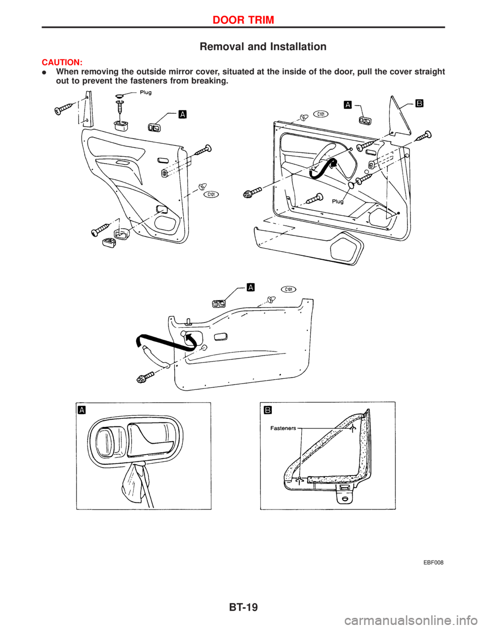
Removal and Installation
CAUTION:
IWhen removing the outside mirror cover, situated at the inside of the door, pull the cover straight
out to prevent the fasteners from breaking.
EBF008
DOOR TRIM
BT-19
Page 336 of 1767
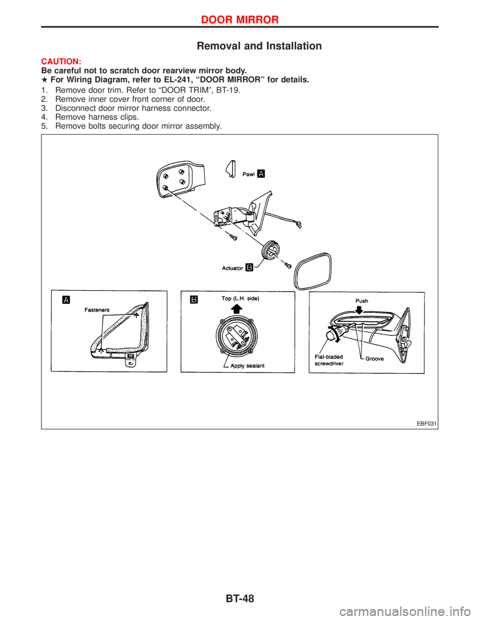
Removal and Installation
CAUTION:
Be careful not to scratch door rearview mirror body.
HFor Wiring Diagram, refer to EL-241, ªDOOR MIRRORº for details.
1. Remove door trim. Refer to ªDOOR TRIMº, BT-19.
2. Remove inner cover front corner of door.
3. Disconnect door mirror harness connector.
4. Remove harness clips.
5. Remove bolts securing door mirror assembly.
EBF031
DOOR MIRROR
BT-48
Page 390 of 1767
REMOVAL
1. Remove the following:
IEngine coolant draining
ICharge air cooler
IAir inlet pipe
IThrottle body
IRocker cover
IOil level gauge guide
IEGR cooler
IEGR guide tube
IEGR volume control solenoid valve
IFuel hose
IInjection tube
IRadiator upper hose
IRadiator shroud
ICooling fan
IDrive belt
IVacuum pipe
IVacuum pump
2. Move the power steering pump.
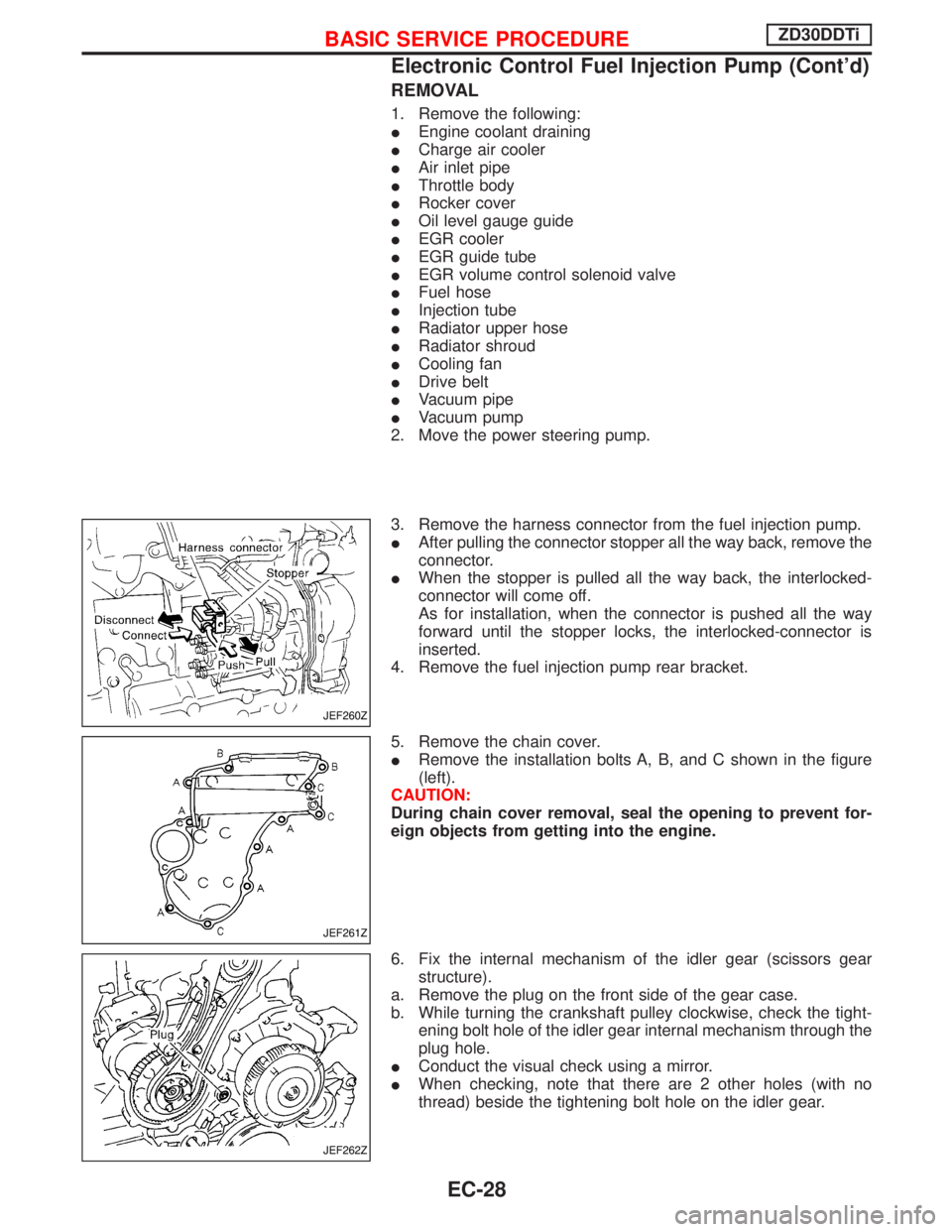
3. Remove the harness connector from the fuel injection pump.
IAfter pulling the connector stopper all the way back, remove the
connector.
IWhen the stopper is pulled all the way back, the interlocked-
connector will come off.
As for installation, when the connector is pushed all the way
forward until the stopper locks, the interlocked-connector is
inserted.
4. Remove the fuel injection pump rear bracket.
5. Remove the chain cover.
IRemove the installation bolts A, B, and C shown in the figure
(left).
CAUTION:
During chain cover removal, seal the opening to prevent for-
eign objects from getting into the engine.
6. Fix the internal mechanism of the idler gear (scissors gear
structure).
a. Remove the plug on the front side of the gear case.
b. While turning the crankshaft pulley clockwise, check the tight-
ening bolt hole of the idler gear internal mechanism through the
plug hole.
IConduct the visual check using a mirror.
IWhen checking, note that there are 2 other holes (with no
thread) beside the tightening bolt hole on the idler gear.
JEF260Z
JEF261Z
JEF262Z
BASIC SERVICE PROCEDUREZD30DDTi
Electronic Control Fuel Injection Pump (Cont'd)
EC-28
Page 817 of 1767

ELECTRICAL SYSTEM
SECTION
EL
When you read wiring diagrams:
IRead GI section, ªHOW TO READ WIRING DIAGRAMSº.
CONTENTS
HARNESS CONNECTOR................................................3
Description ...................................................................3
STANDARDIZED RELAYS..............................................4
Description ...................................................................4
POWER SUPPLY ROUTING...........................................6
Schematic ....................................................................6
Wiring Diagram - POWER - ........................................8
Fuse ...........................................................................17
Fusible Link................................................................17
Circuit Breaker Inspection .........................................17
GROUND DISTRIBUTION.............................................18
COMBINATION SWITCH...............................................23
Check .........................................................................23
Replacement ..............................................................24
STEERING SWITCH......................................................25
Check .........................................................................25
HEADLAMP - Without Daytime Light System -.........26
Wiring Diagram - H/LAMP -.......................................26
HEADLAMP - Daytime Light System -.......................29
Operation ...................................................................29
Schematic ..................................................................30
Wiring Diagram - DTRL - ...........................................31
HEADLAMP - Headlamp Aiming Control -.................37
Description .................................................................37
Replacing Headlamp Aiming Actuator .......................38
Wiring Diagram - H/AIM - ..........................................39
Trouble Diagnoses.....................................................42
HEADLAMP...................................................................43
Bulb Replacement .....................................................43
Aiming Adjustment .....................................................43
EXTERIOR LAMP..........................................................45
Wiring Diagram - TAIL/L - ..........................................45
Wiring Diagram - STOP/L - .......................................48
Wiring Diagram - BACK/L - .......................................49
Wiring Diagram - F/FOG - .........................................51
Front Fog Lamp Aiming Adjustment ..........................53
Wiring Diagram - R/FOG -.........................................54
Schematic ..................................................................55Wiring Diagram - TURN - ..........................................56
Bulb Specifications ....................................................60
INTERIOR LAMP...........................................................61
Schematic ..................................................................61
Wiring Diagram - ILL - ...............................................62
Wiring Diagram - INT/L - ...........................................66
METER AND GAUGES.................................................70
Combination Meter ....................................................70
Schematic ..................................................................71
Wiring Diagram - METER - .......................................72
Combination Meter Self-Diagnosis ............................76
Components Inspection .............................................78
Trouble Diagnoses.....................................................79
Fuel Tank Gauge Unit Check ....................................80
Thermal Transmitter Check .......................................80
Oil Pressure Switch Check ........................................80
WARNING LAMPS AND CHIME...................................81
Schematic ..................................................................81
Wiring Diagram - WARN - .........................................82
Diode Check ..............................................................92
Wiring Diagram - CHIME - ........................................93
WIPER AND WASHER..................................................94
Wiring Diagram - WIPER - ........................................94
Wiring Diagram - WIP/R -..........................................96
Installation ..................................................................98
Washer Nozzle Adjustment .......................................99
Check Valve ...............................................................99
Wiring Diagram - HLC - ...........................................100
HORN, CIGARETTE LIGHTER AND CLOCK............104
Wiring Diagram - HORN - .......................................104
Wiring Diagram - CIGAR -.......................................105
Wiring Diagram - CLOCK -......................................106
REAR WINDOW DEFOGGER AND DOOR
MIRROR DEFOGGER.................................................107
Wiring Diagram - DEF - ...........................................107
Filament Check ........................................................109
Filament Repair ....................................................... 110
AUDIO.......................................................................... 111
Page 818 of 1767
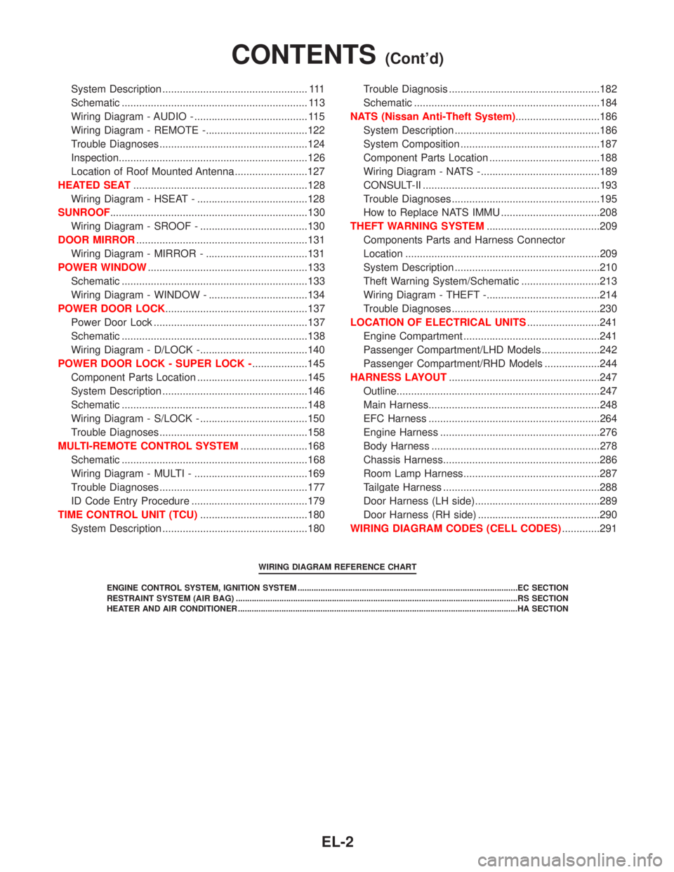
System Description .................................................. 111
Schematic ................................................................ 113
Wiring Diagram - AUDIO - ....................................... 115
Wiring Diagram - REMOTE -...................................122
Trouble Diagnoses...................................................124
Inspection.................................................................126
Location of Roof Mounted Antenna .........................127
HEATED SEAT............................................................128
Wiring Diagram - HSEAT - ......................................128
SUNROOF....................................................................130
Wiring Diagram - SROOF - .....................................130
DOOR MIRROR...........................................................131
Wiring Diagram - MIRROR - ...................................131
POWER WINDOW.......................................................133
Schematic ................................................................133
Wiring Diagram - WINDOW - ..................................134
POWER DOOR LOCK.................................................137
Power Door Lock .....................................................137
Schematic ................................................................138
Wiring Diagram - D/LOCK -.....................................140
POWER DOOR LOCK - SUPER LOCK -...................145
Component Parts Location ......................................145
System Description ..................................................146
Schematic ................................................................148
Wiring Diagram - S/LOCK - .....................................150
Trouble Diagnoses...................................................158
MULTI-REMOTE CONTROL SYSTEM.......................168
Schematic ................................................................168
Wiring Diagram - MULTI - .......................................169
Trouble Diagnoses...................................................177
ID Code Entry Procedure ........................................179
TIME CONTROL UNIT (TCU).....................................180
System Description ..................................................180Trouble Diagnosis ....................................................182
Schematic ................................................................184
NATS (Nissan Anti-Theft System).............................186
System Description ..................................................186
System Composition ................................................187
Component Parts Location ......................................188
Wiring Diagram - NATS -.........................................189
CONSULT-II .............................................................193
Trouble Diagnoses...................................................195
How to Replace NATS IMMU ..................................208
THEFT WARNING SYSTEM.......................................209
Components Parts and Harness Connector
Location ...................................................................209
System Description ..................................................210
Theft Warning System/Schematic ...........................213
Wiring Diagram - THEFT -.......................................214
Trouble Diagnoses...................................................230
LOCATION OF ELECTRICAL UNITS.........................241
Engine Compartment ...............................................241
Passenger Compartment/LHD Models ....................242
Passenger Compartment/RHD Models ...................244
HARNESS LAYOUT....................................................247
Outline......................................................................247
Main Harness...........................................................248
EFC Harness ...........................................................264
Engine Harness .......................................................276
Body Harness ..........................................................278
Chassis Harness......................................................286
Room Lamp Harness...............................................287
Tailgate Harness ......................................................288
Door Harness (LH side)...........................................289
Door Harness (RH side) ..........................................290
WIRING DIAGRAM CODES (CELL CODES).............291
WIRING DIAGRAM REFERENCE CHART
ENGINE CONTROL SYSTEM, IGNITION SYSTEM ................................................................................................EC SECTION
RESTRAINT SYSTEM (AIR BAG) ...........................................................................................................................RS SECTION
HEATER AND AIR CONDITIONER ..........................................................................................................................HA SECTION
CONTENTS(Cont'd)
EL-2
Page 838 of 1767
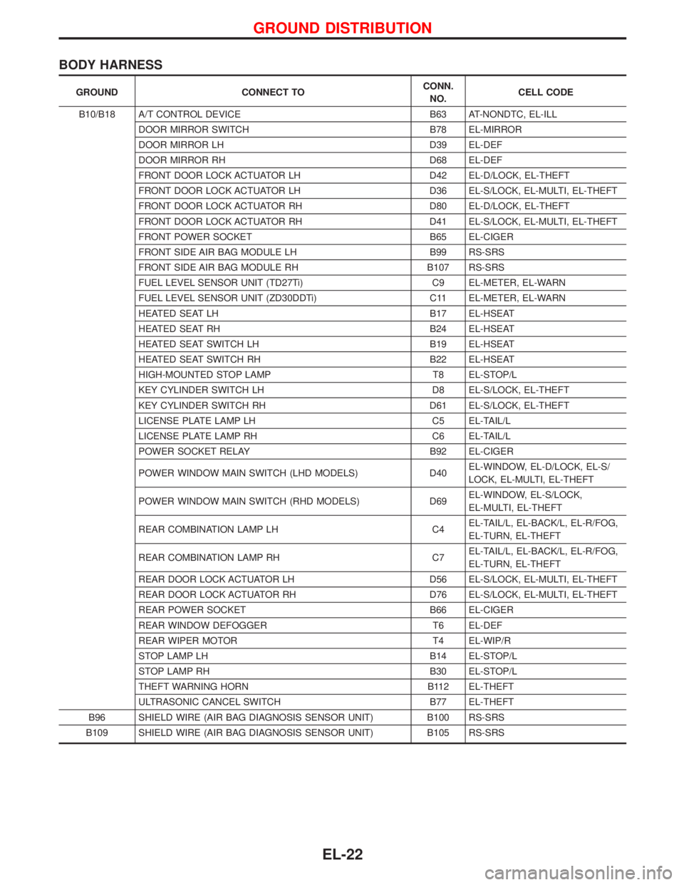
BODY HARNESS
GROUND CONNECT TOCONN.
NO.CELL CODE
B10/B18 A/T CONTROL DEVICE B63 AT-NONDTC, EL-ILL
DOOR MIRROR SWITCH B78 EL-MIRROR
DOOR MIRROR LH D39 EL-DEF
DOOR MIRROR RH D68 EL-DEF
FRONT DOOR LOCK ACTUATOR LH D42 EL-D/LOCK, EL-THEFT
FRONT DOOR LOCK ACTUATOR LH D36 EL-S/LOCK, EL-MULTI, EL-THEFT
FRONT DOOR LOCK ACTUATOR RH D80 EL-D/LOCK, EL-THEFT
FRONT DOOR LOCK ACTUATOR RH D41 EL-S/LOCK, EL-MULTI, EL-THEFT
FRONT POWER SOCKET B65 EL-CIGER
FRONT SIDE AIR BAG MODULE LH B99 RS-SRS
FRONT SIDE AIR BAG MODULE RH B107 RS-SRS
FUEL LEVEL SENSOR UNIT (TD27Ti) C9 EL-METER, EL-WARN
FUEL LEVEL SENSOR UNIT (ZD30DDTi) C11 EL-METER, EL-WARN
HEATED SEAT LH B17 EL-HSEAT
HEATED SEAT RH B24 EL-HSEAT
HEATED SEAT SWITCH LH B19 EL-HSEAT
HEATED SEAT SWITCH RH B22 EL-HSEAT
HIGH-MOUNTED STOP LAMP T8 EL-STOP/L
KEY CYLINDER SWITCH LH D8 EL-S/LOCK, EL-THEFT
KEY CYLINDER SWITCH RH D61 EL-S/LOCK, EL-THEFT
LICENSE PLATE LAMP LH C5 EL-TAIL/L
LICENSE PLATE LAMP RH C6 EL-TAIL/L
POWER SOCKET RELAY B92 EL-CIGER
POWER WINDOW MAIN SWITCH (LHD MODELS) D40EL-WINDOW, EL-D/LOCK, EL-S/
LOCK, EL-MULTI, EL-THEFT
POWER WINDOW MAIN SWITCH (RHD MODELS) D69EL-WINDOW, EL-S/LOCK,
EL-MULTI, EL-THEFT
REAR COMBINATION LAMP LH C4EL-TAIL/L, EL-BACK/L, EL-R/FOG,
EL-TURN, EL-THEFT
REAR COMBINATION LAMP RH C7EL-TAIL/L, EL-BACK/L, EL-R/FOG,
EL-TURN, EL-THEFT
REAR DOOR LOCK ACTUATOR LH D56 EL-S/LOCK, EL-MULTI, EL-THEFT
REAR DOOR LOCK ACTUATOR RH D76 EL-S/LOCK, EL-MULTI, EL-THEFT
REAR POWER SOCKET B66 EL-CIGER
REAR WINDOW DEFOGGER T6 EL-DEF
REAR WIPER MOTOR T4 EL-WIP/R
STOP LAMP LH B14 EL-STOP/L
STOP LAMP RH B30 EL-STOP/L
THEFT WARNING HORN B112 EL-THEFT
ULTRASONIC CANCEL SWITCH B77 EL-THEFT
B96 SHIELD WIRE (AIR BAG DIAGNOSIS SENSOR UNIT) B100 RS-SRS
B109 SHIELD WIRE (AIR BAG DIAGNOSIS SENSOR UNIT) B105 RS-SRS
GROUND DISTRIBUTION
EL-22
Page 923 of 1767
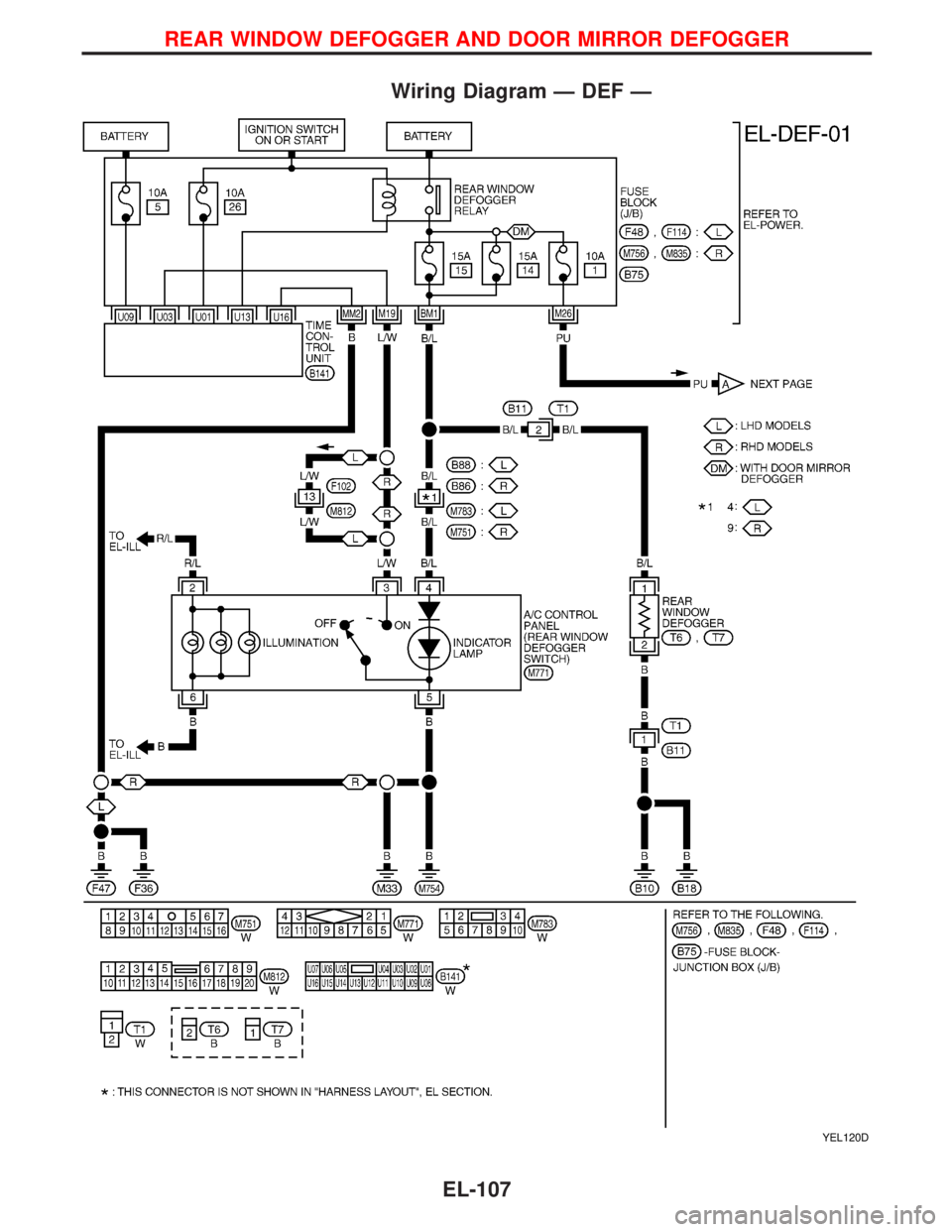
Wiring Diagram Ð DEF Ð
YEL120D
REAR WINDOW DEFOGGER AND DOOR MIRROR DEFOGGER
EL-107