2002 NISSAN TERRANO wheel alignment
[x] Cancel search: wheel alignmentPage 235 of 1767
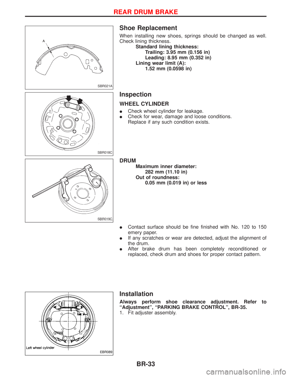
Shoe Replacement
When installing new shoes, springs should be changed as well.
Check lining thickness.
Standard lining thickness:
Trailing: 3.95 mm (0.156 in)
Leading: 8.95 mm (0.352 in)
Lining wear limit (A):
1.52 mm (0.0598 in)
Inspection
WHEEL CYLINDER
ICheck wheel cylinder for leakage.
ICheck for wear, damage and loose conditions.
Replace if any such condition exists.
DRUM
Maximum inner diameter:
282 mm (11.10 in)
Out of roundness:
0.05 mm (0.019 in) or less
IContact surface should be fine finished with No. 120 to 150
emery paper.
IIf any scratches or wear are detected, adjust the alignment of
the drum.
IAfter brake drum has been completely reconditioned or
replaced, check drum and shoes for proper contact pattern.
Installation
Always perform shoe clearance adjustment. Refer to
ªAdjustmentº, ªPARKING BRAKE CONTROLº, BR-35.
1. Fit adjuster assembly.
SBR021A
SBR018C
SBR019C
EBR089
REAR DRUM BRAKE
BR-33
Page 262 of 1767
![NISSAN TERRANO 2002 Service Repair Manual SELF-DIAGNOSTIC RESULTS MODE
Diagnostic item Diagnostic item is detected when...Diagnostic
procedure
FR RH SENSORH
[OPEN]ICircuit for front right wheel sensor is open.
(An abnormally high input voltag NISSAN TERRANO 2002 Service Repair Manual SELF-DIAGNOSTIC RESULTS MODE
Diagnostic item Diagnostic item is detected when...Diagnostic
procedure
FR RH SENSORH
[OPEN]ICircuit for front right wheel sensor is open.
(An abnormally high input voltag](/manual-img/5/57393/w960_57393-261.png)
SELF-DIAGNOSTIC RESULTS MODE
Diagnostic item Diagnostic item is detected when...Diagnostic
procedure
FR RH SENSORH
[OPEN]ICircuit for front right wheel sensor is open.
(An abnormally high input voltage is entered.)4
FR LH SENSORH
[OPEN]ICircuit for front left wheel sensor is open.
(An abnormally high input voltage is entered.)4
RR RH SENSORH
[OPEN]ICircuit for rear right sensor is open.
(An abnormally high input voltage is entered.)4
RR LH SENSORH
[OPEN]ICircuit for rear left sensor is open.
(An abnormally high input voltage is entered.)4
FR RH SENSORH
[SHORT]ICircuit for front right wheel sensor is shorted.
(An abnormally low input voltage is entered.)4
FR LH SENSORH
[SHORT]ICircuit for front left wheel sensor is shorted.
(An abnormally low input voltage is entered.)4
RR RH SENSORH
[SHORT]ICircuit for rear right sensor is shorted.
(An abnormally low input voltage is entered.)4
RR LH SENSORH
[SHORT]ICircuit for rear left sensor is shorted.
(An abnormally low input voltage is entered.)4
ABS SENSORH
[ABNORMAL SIGNAL]ITeeth damage on sensor rotor or misalignment of wheel sensor.
(Abnormal wheel sensor signal is entered.)4
FR RH IN ABS SOL
[OPEN, SHORT]ICircuit for front right inlet solenoid valve is open or shorted.
(An abnormally low output voltage is entered.)3
FR LH IN ABS SOL
[OPEN, SHORT]ICircuit for front left inlet solenoid valve is open or shorted.
(An abnormally low output voltage is entered.)3
FR RH OUT ABS SOL
[OPEN, SHORT]ICircuit for front right outlet solenoid valve is open or shorted.
(An abnormally low output voltage is entered.)3
FR LH OUT ABS SOL
[OPEN, SHORT]ICircuit for front left outlet solenoid valve is open or shorted.
(An abnormally low output voltage is entered.)3
RR IN ABS SOL
[OPEN, SHORT]ICircuit for rear right outlet solenoid valve is open or shorted.
(An abnormally high output voltage is entered.)3
RR OUT ABS SOL
[OPEN, SHORT]ICircuit for rear left outlet solenoid valve is open or shorted.
(An abnormally high output voltage is entered.)3
ABS ACTUATOR RELAY
[ABNORMAL]IActuator solenoid valve relay is ON, even if control unit sends OFF signal.
IActuator solenoid valve relay is OFF, even if control unit sends ON signal.6
ABS MOTOR RELAY
[ABNORMAL]ICircuit for ABS motor relay is open or shorted.
ICircuit for actuator motor is open or shorted.
IActuator motor relay is stuck.5
BATTERY VOLT
[VB-LOW]IPower source voltage supplied to ABS control unit is abnormally low. 7
CONTROL UNITIFunction of calculation in ABS control unit has failed. 9
G-SENSOR
[ABNORMAL]IG sensor is open.8
HIf a tire slips on rough roads for more than 10 seconds, the ABS warning lamp may come on. In this case, the malfunctioning code
regarding the wheel sensors may be memorized. Turn off the ignition switch, restart the engine and drive the vehicle at speeds
above 30 km/h (19 MPH).
TROUBLE DIAGNOSES
CONSULT-II Inspection Procedure (Cont'd)
BR-60
Page 1259 of 1767
FRONT AXLE & FRONT SUSPENSION
SECTION
FA
CONTENTS
PRECAUTIONS...............................................................2
PREPARATION................................................................3
FRONT AXLE AND FRONT SUSPENSION...................4
CHECK AND ADJUSTMENT..........................................5
Front Axle and Front Suspension Parts ......................5
Front Wheel Bearing....................................................6
Front Wheel Alignment ................................................8
Drive Shaft .................................................................12
FRONT AXLE................................................................13
FRONT AXLE - Auto-lock Free-running Hub.............14
Removal and Installation ...........................................14
Inspection...................................................................14
Trouble-shooting ........................................................15
FRONT AXLE - Wheel Hub and Rotor Disc...............18
Removal and Installation ...........................................18
Disassembly...............................................................18
Inspection...................................................................19
Assembly ...................................................................19
FRONT AXLE - Knuckle Spindle.................................20
Removal .....................................................................20Inspection...................................................................21
Installation ..................................................................21
FRONT AXLE - Drive Shaft..........................................22
Removal and Installation ...........................................22
Removal .....................................................................22
Disassembly...............................................................24
Inspection...................................................................25
Assembly ...................................................................25
Installation ..................................................................28
FRONT SUSPENSION..................................................29
Shock Absorber .........................................................30
Torsion Bar.................................................................30
Stabilizer Bar .............................................................33
Upper Link .................................................................33
Compression Rod ......................................................35
Lower Link .................................................................35
Upper Ball Joint and Lower Ball Joint .......................36
SERVICE DATA AND SPECIFICATIONS (SDS)..........38
General Specifications ...............................................38
Inspection and Adjustment ........................................39
Page 1260 of 1767
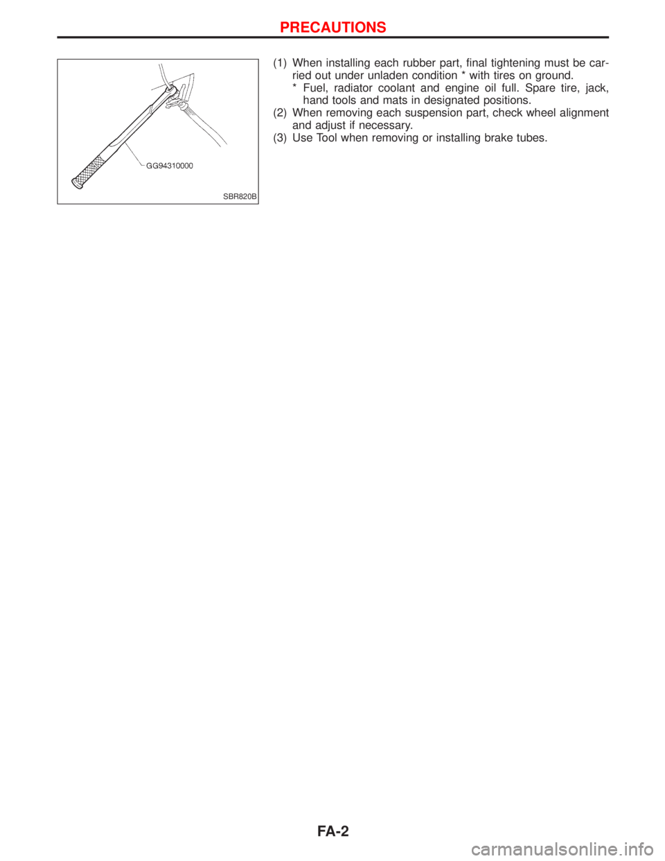
(1) When installing each rubber part, final tightening must be car-
ried out under unladen condition * with tires on ground.
* Fuel, radiator coolant and engine oil full. Spare tire, jack,
hand tools and mats in designated positions.
(2) When removing each suspension part, check wheel alignment
and adjust if necessary.
(3) Use Tool when removing or installing brake tubes.
SBR820B
PRECAUTIONS
FA-2
Page 1266 of 1767
Front Wheel Alignment
Before checking front wheel alignment, be sure to make a prelimi-
nary inspection.
PRELIMINARY INSPECTION
1. Check the tires for wear and proper inflation.
2. Check the wheel runout.
Wheel runout:
Refer to SDS, FA-39.
3. Check the front wheel bearings for looseness.
4. Check the front suspension for looseness.
5. Check the steering linkage for looseness.
6. Check that the front shock absorbers work properly by using
the standard bounce test.
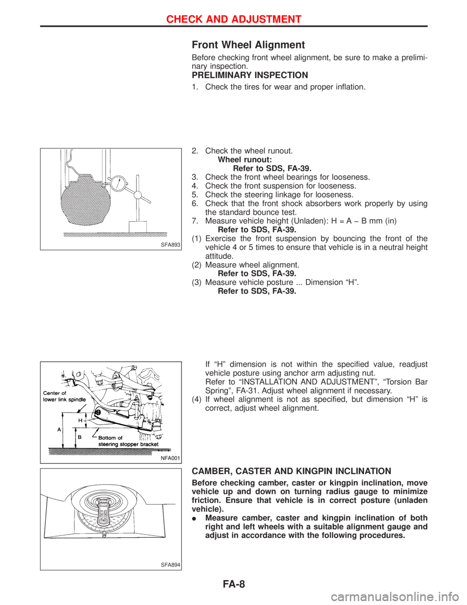
7. Measure vehicle height (Unladen): H = A þ B mm (in)
Refer to SDS, FA-39.
(1) Exercise the front suspension by bouncing the front of the
vehicle 4 or 5 times to ensure that vehicle is in a neutral height
attitude.
(2) Measure wheel alignment.
Refer to SDS, FA-39.
(3) Measure vehicle posture ... Dimension ªHº.
Refer to SDS, FA-39.
If ªHº dimension is not within the specified value, readjust
vehicle posture using anchor arm adjusting nut.
Refer to ªINSTALLATION AND ADJUSTMENTº, ªTorsion Bar
Springº, FA-31. Adjust wheel alignment if necessary.
(4) If wheel alignment is not as specified, but dimension ªHº is
correct, adjust wheel alignment.
CAMBER, CASTER AND KINGPIN INCLINATION
Before checking camber, caster or kingpin inclination, move
vehicle up and down on turning radius gauge to minimize
friction. Ensure that vehicle is in correct posture (unladen
vehicle).
IMeasure camber, caster and kingpin inclination of both
right and left wheels with a suitable alignment gauge and
adjust in accordance with the following procedures.
SFA893
NFA001
SFA894
CHECK AND ADJUSTMENT
FA-8
Page 1267 of 1767
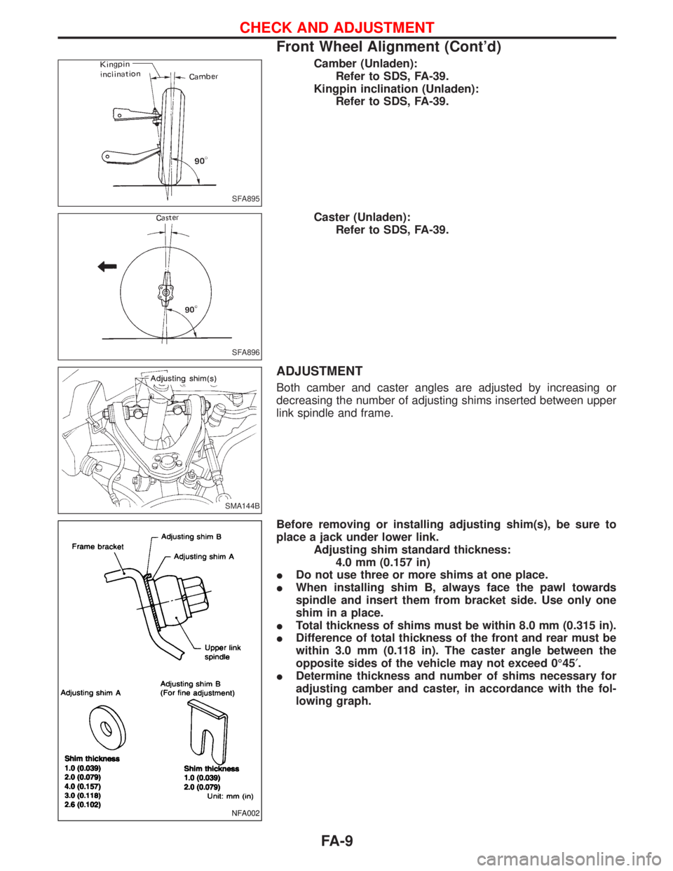
Camber (Unladen):
Refer to SDS, FA-39.
Kingpin inclination (Unladen):
Refer to SDS, FA-39.
Caster (Unladen):
Refer to SDS, FA-39.
ADJUSTMENT
Both camber and caster angles are adjusted by increasing or
decreasing the number of adjusting shims inserted between upper
link spindle and frame.
Before removing or installing adjusting shim(s), be sure to
place a jack under lower link.
Adjusting shim standard thickness:
4.0 mm (0.157 in)
IDo not use three or more shims at one place.
IWhen installing shim B, always face the pawl towards
spindle and insert them from bracket side. Use only one
shim in a place.
ITotal thickness of shims must be within 8.0 mm (0.315 in).
IDifference of total thickness of the front and rear must be
within 3.0 mm (0.118 in). The caster angle between the
opposite sides of the vehicle may not exceed 0É45¢.
IDetermine thickness and number of shims necessary for
adjusting camber and caster, in accordance with the fol-
lowing graph.
SFA895
SFA896
SMA144B
NFA002
CHECK AND ADJUSTMENT
Front Wheel Alignment (Cont'd)
FA-9
Page 1268 of 1767
![NISSAN TERRANO 2002 Service Repair Manual [Example]
(Measures taken at one side):
(1)
Angle
Specified value Measured Change
Camber angle 0É30¢0É5¢+0É25¢
Caster angle 1É54¢2É10¢þ0É16¢
The above values relate to the graph below:
Sh NISSAN TERRANO 2002 Service Repair Manual [Example]
(Measures taken at one side):
(1)
Angle
Specified value Measured Change
Camber angle 0É30¢0É5¢+0É25¢
Caster angle 1É54¢2É10¢þ0É16¢
The above values relate to the graph below:
Sh](/manual-img/5/57393/w960_57393-1267.png)
[Example]
(Measures taken at one side):
(1)
Angle
Specified value Measured Change
Camber angle 0É30¢0É5¢+0É25¢
Caster angle 1É54¢2É10¢þ0É16¢
The above values relate to the graph below:
Shim thickness selection graph
(2) Obtain intersection point of lines in accordance with the graph.
Front: 1.4 mm
Rear: 2.0 mm
(3) Choose shims which are nearest to the values found in the
graph:
Front: 1.6 mm
Rear: 2.0 mm
(4) If shim thicknesses as calculated appear not to be available,
combinations of different shims should be used to meet the
desired total thickness of the shims.
EFA015
CHECK AND ADJUSTMENT
Front Wheel Alignment (Cont'd)
FA-10
Page 1269 of 1767
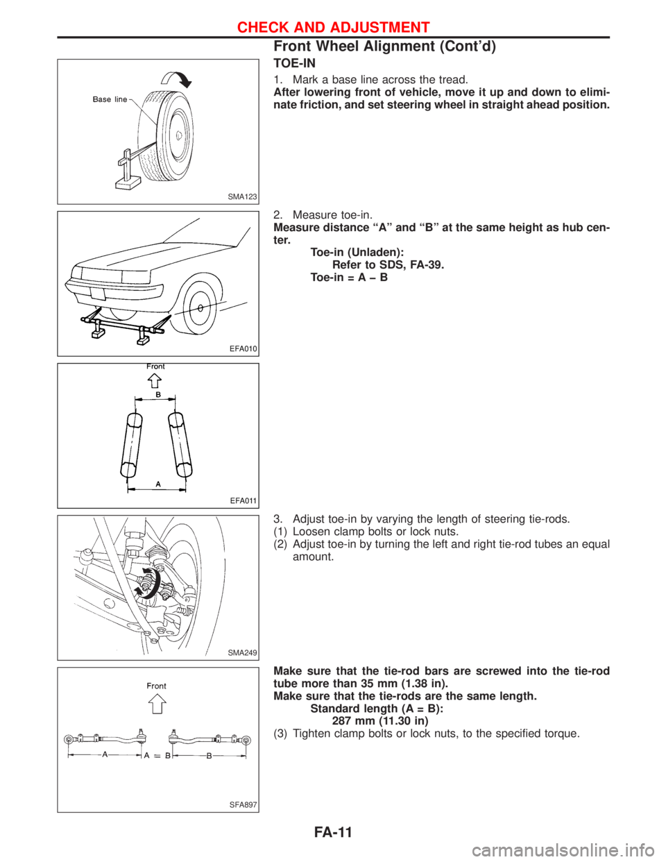
TOE-IN
1. Mark a base line across the tread.
After lowering front of vehicle, move it up and down to elimi-
nate friction, and set steering wheel in straight ahead position.
2. Measure toe-in.
Measure distance ªAº and ªBº at the same height as hub cen-
ter.
Toe-in (Unladen):
Refer to SDS, FA-39.
Toe-in = A þ B
3. Adjust toe-in by varying the length of steering tie-rods.
(1) Loosen clamp bolts or lock nuts.
(2) Adjust toe-in by turning the left and right tie-rod tubes an equal
amount.
Make sure that the tie-rod bars are screwed into the tie-rod
tube more than 35 mm (1.38 in).
Make sure that the tie-rods are the same length.
Standard length (A = B):
287 mm (11.30 in)
(3) Tighten clamp bolts or lock nuts, to the specified torque.
SMA123
EFA010
EFA011
SMA249
SFA897
CHECK AND ADJUSTMENT
Front Wheel Alignment (Cont'd)
FA-11