2002 NISSAN TERRANO warning
[x] Cancel search: warningPage 6 of 1767
Supplemental Restraint System (SRS) ªAIR
BAGº and ªSEAT BELT PRE-TENSIONERº
The Supplemental Restraint System such as ªAIR BAGº and ªSEAT BELT PRE-TENSIONERº used along with
a seat belt, helps to reduce the risk or severity of injury to the driver and front passenger in a frontal collision.
The SRS system composition which is available to NISSAN MODEL R20 is as follows (The composition var-
ies according to the destination.):
Driver air bag module (located in the center of the steering wheel), front passenger air bag module (located
on the instrument panel on passenger side), seat belt pre-tensioner, a diagnosis sensor unit, warning lamp,
wiring harness and spiral cable.
Information necessary to service the system safely is included in theRS sectionof this Service Manual.
WARNING:
ITo avoid rendering the SRS inoperative, which could increase the risk of personal injury or death
in the event of a collision which would result in air bag inflation, all maintenance must be performed
by an authorized NISSAN dealer.
IImproper maintenance, including incorrect removal and installation of the SRS, can lead to per-
sonal injury caused by unintentional activation of the system. For removal of Spiral Cable and Air
Bag Module, see the RS section.
IDo not use electrical test equipment on any circuit related to the SRS unless instructed to in this
Service Manual. Spiral cable and wiring harnesses covered with yellow insulation either just before
the harness connectors or for the complete harness are related to the SRS.
Precautions
IBefore proceeding with disassembly, thoroughly clean the outside of the transmission. It is important to
prevent the internal parts from becoming contaminated by dirt or other foreign matter.
IDisassembly should be done in a clean work area.
IUse lint-free cloth or towels for wiping parts clean. Common shop rags can leave fibers that could inter-
fere with the operation of the transmission.
IPlace disassembled parts in order for easier and proper assembly.
IAll parts should be carefully cleaned with a general purpose, non-flammable solvent before inspection or
reassembly.
IGaskets, seals and O-rings should be replaced any time the transmission is disassembled.
IIt is very important to perform functional tests whenever they are indicated.
IThe valve body contains precision parts and requires extreme care when parts are removed and serviced.
Place removed parts in a parts rack in order to replace them in correct positions and sequences. Care will
also prevent springs and small parts from becoming scattered or lost.
IProperly installed valves, sleeves, plugs, etc. will slide along bores in valve body under their own weight.
IBefore assembly, apply a coat of recommended ATF to all parts. Apply petroleum jelly to protect O-rings
and seals, and to hold bearings and washers in place during assembly. Do not use grease.
IExtreme care should be taken to avoid damage to O-rings, seals and gaskets when assembling.
IAfter overhaul, refill the transmission with new ATF.
IWhen the A/T drain plug is removed, only some of the fluid is drained. Old A/T fluid will remain in torque
converter and ATF cooling system.
Always follow the procedures under ªChanging A/T Fluidº in the MA section when changing A/T fluid.
PREPARATION AND PRECAUTIONS
AT- 4
Page 95 of 1767
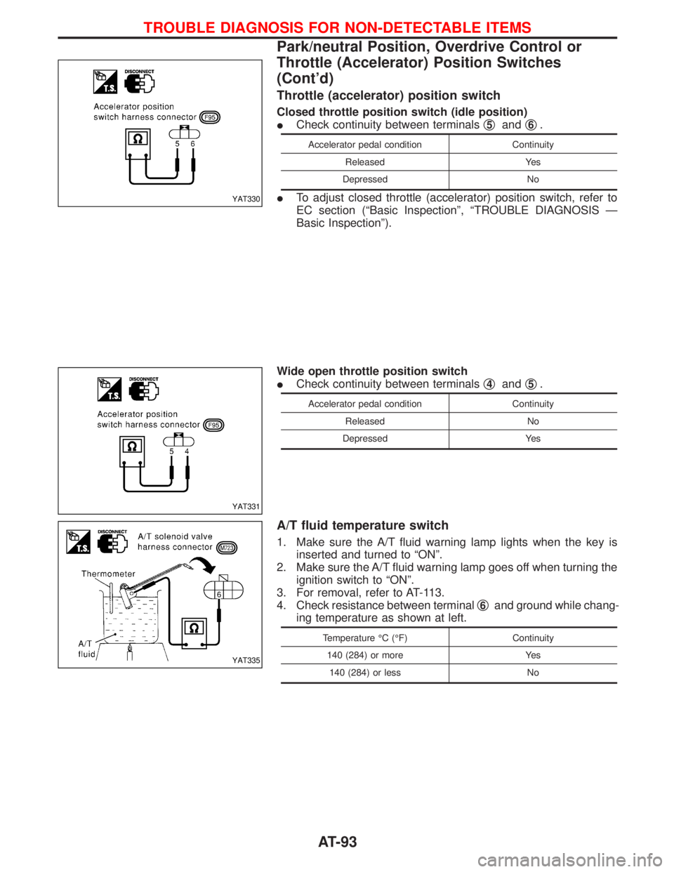
Throttle (accelerator) position switch
Closed throttle position switch (idle position)
ICheck continuity between terminalsq
5andq6.
Accelerator pedal condition Continuity
Released Yes
Depressed No
ITo adjust closed throttle (accelerator) position switch, refer to
EC section (ªBasic Inspectionº, ªTROUBLE DIAGNOSIS Ð
Basic Inspectionº).
Wide open throttle position switch
ICheck continuity between terminalsq
4andq5.
Accelerator pedal condition Continuity
Released No
Depressed Yes
A/T fluid temperature switch
1. Make sure the A/T fluid warning lamp lights when the key is
inserted and turned to ªONº.
2. Make sure the A/T fluid warning lamp goes off when turning the
ignition switch to ªONº.
3. For removal, refer to AT-113.
4. Check resistance between terminalq
6and ground while chang-
ing temperature as shown at left.
Temperature ÉC (ÉF) Continuity
140 (284) or more Yes
140 (284) or less No
YAT330
YAT331
YAT335
TROUBLE DIAGNOSIS FOR NON-DETECTABLE ITEMS
Park/neutral Position, Overdrive Control or
Throttle (Accelerator) Position Switches
(Cont'd)
AT-93
Page 96 of 1767
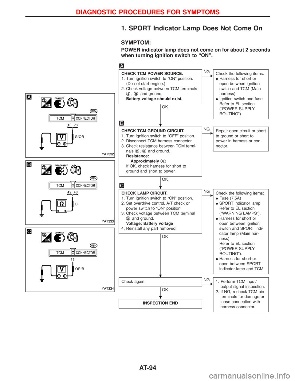
1. SPORT Indicator Lamp Does Not Come On
SYMPTOM:
POWER indicator lamp does not come on for about 2 seconds
when turning ignition switch to ªONº.
CHECK TCM POWER SOURCE.
1. Turn ignition switch to ªONº position.
(Do not start engine.)
2. Check voltage between TCM terminals
q
4,q9and ground.
Battery voltage should exist.
OK
ENG
Check the following items:
IHarness for short or
open between ignition
switch and TCM (Main
harness)
IIgnition switch and fuse
Refer to EL section
(ªPOWER SUPPLY
ROUTINGº).
CHECK TCM GROUND CIRCUIT.
1. Turn ignition switch to ªOFFº position.
2. Disconnect TCM harness connector.
3. Check resistance between TCM termi-
nalsq
15,q48and ground.
Resistance:
Approximately 0W
If OK, check harness for short to
ground and short to power.
OK
ENG
Repair open circuit or short
to ground or short to
power in harness or con-
nector.
CHECK LAMP CIRCUIT.
1. Turn ignition switch to ªONº position.
2. Set overdrive control, A/T check or
power switch to ªONº position.
3. Check voltage between TCM terminal
q
39and ground.
Voltage: Battery voltage
4. Reinstall any part removed.
OK
ENG
Check the following items:
IFuse (7.5A)
ISPORT indicator lamp
Refer to EL section
(ªWARNING LAMPSº).
IHarness for short or
open between ignition
switch and SPORT indi-
cator lamp (Main har-
ness)
Refer to EL section
(ªPOWER SUPPLY
ROUTINGº).
IHarness for short or
open between SPORT
indicator lamp and TCM
Check again.
OK
ENG
1. Perform TCM input/
output signal inspection.
2. If NG, recheck TCM pin
terminals for damage or
loose connection with
harness connector.
INSPECTION END
YAT332
YAT333
YAT334
H
H
H H
H
DIAGNOSTIC PROCEDURES FOR SYMPTOMS
AT-94
Page 204 of 1767
Diagnostic Procedure 2 (Warning lamp stays on
when ignition switch is turned ON)............................69
Diagnostic Procedure 3 (ABS actuator solenoid
valve and solenoid valve relay) .................................71
Diagnostic Procedure 4 (Wheel sensor or rotor) ......73
Diagnostic Procedure 5 (Motor Relay or motor) .......75
Diagnostic Procedure 7 (Low voltage) ......................77
Diagnostic Procedure 8 (G sensor) ...........................78
Diagnostic Procedure 9 (Control unit) .......................79
Diagnostic Procedure 10 (Pedal vibration and
noise) .........................................................................80Diagnostic Procedure 11 (Long stopping
distance) ....................................................................80
Diagnostic Procedure 12 (Unexpected pedal
action) ........................................................................81
Diagnostic Procedure 13 ...........................................82
Diagnostic Procedure 14 ...........................................82
Electrical Components Inspection .............................83
SERVICE DATA AND SPECIFICATIONS (SDS)..........84
General Specifications ...............................................84
Inspection and Adjustment ........................................85
CONTENTS(Cont'd)
BR-2
Page 205 of 1767
Supplement Restraint System (SRS) ªAIR BAGº
and ªSEAT BELT PRE-TENSIONERº
The Supplemental Restraint System ªAir Bagº and ªSeat Belt Pre-tensionerº, used along with a seat belt, help
to reduce the risk or severity or injury to the driver and front passenger in a collision. The Supplemental
Restraint System consists of an air bag module (located in the center of the steering wheel and on the instru-
ment panel on the passenger side, where fitted), seat belt pre-tensioners, a diagnosis sensor unit, warning
lamp, wiring harness and spiral cable. Information necessary to service the system safely is included in the
BT sectionof this Service Manual.
WARNING:
ITo avoid rendering the SRS inoperative (which could increase the risk of personal injury or death
in the event of a collision which would result in air bag inflation), all maintenance must be per-
formed by an authorized NISSAN dealer.
IImproper maintenance, including incorrect removal and installation of the SRS, can lead to per-
sonal injury caused by unintentional activation of the system.
IDo not use electrical test equipment on any circuit related to the SRS unless instructed to in this
Service Manual. SRS wiring harnesses (except ªSEAT BELT-TENSIONERº connector) can be iden-
tified with yellow harness connector and with yellow harness protector or yellow insulation tape
before the harness connectors.
Precautions
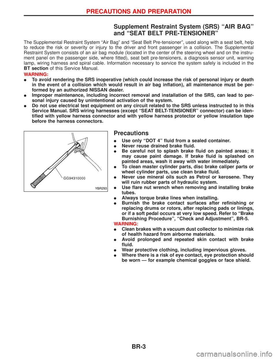
IUse only ªDOT 4º fluid from a sealed container.
INever reuse drained brake fluid.
IBe careful not to splash brake fluid on painted areas; it
may cause paint damage. If brake fluid is splashed on
painted areas, wash it away with water immediately.
ITo clean master cylinder parts, disc brake caliper parts or
wheel cylinder parts, use clean brake fluid.
INever use mineral oils such as Petrol or kerosene. They
will ruin rubber parts of hydraulic system.
IUse flare nut wrench when removing and installing brake
tubes.
IAlways torque brake lines when installing.
IBurnish the brake contact surfaces after refinishing or
replacing drums or rotors, after replacing pads or linings,
or if a soft pedal occurs at very low speed. Refer to ªBrake
Burnishing Procedureº, ªCheck and Adjustmentº, BR-5.
WARNING:
IClean brakes with a vacuum dust collector to minimize risk
of health hazard from airborne materials.
IAvoid prolonged and repeated skin contact with brake
fluid.
IWear protective clothing, including impervious gloves.
IWhere there is a risk of eye contact, eye protection should
be worn Ð for example chemical goggles or face shield.
YBR293
PRECAUTIONS AND PREPARATION
BR-3
Page 207 of 1767
Checking Brake Fluid Level
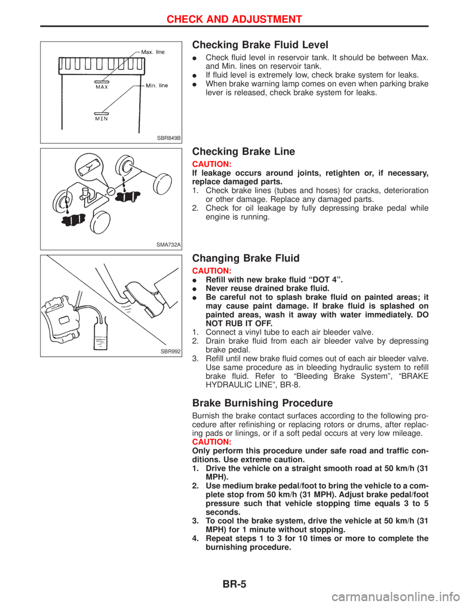
ICheck fluid level in reservoir tank. It should be between Max.
and Min. lines on reservoir tank.
IIf fluid level is extremely low, check brake system for leaks.
IWhen brake warning lamp comes on even when parking brake
lever is released, check brake system for leaks.
Checking Brake Line
CAUTION:
If leakage occurs around joints, retighten or, if necessary,
replace damaged parts.
1. Check brake lines (tubes and hoses) for cracks, deterioration
or other damage. Replace any damaged parts.
2. Check for oil leakage by fully depressing brake pedal while
engine is running.
Changing Brake Fluid
CAUTION:
IRefill with new brake fluid ªDOT 4º.
INever reuse drained brake fluid.
IBe careful not to splash brake fluid on painted areas; it
may cause paint damage. If brake fluid is splashed on
painted areas, wash it away with water immediately. DO
NOT RUB IT OFF.
1. Connect a vinyl tube to each air bleeder valve.
2. Drain brake fluid from each air bleeder valve by depressing
brake pedal.
3. Refill until new brake fluid comes out of each air bleeder valve.
Use same procedure as in bleeding hydraulic system to refill
brake fluid. Refer to ªBleeding Brake Systemº, ªBRAKE
HYDRAULIC LINEº, BR-8.
Brake Burnishing Procedure
Burnish the brake contact surfaces according to the following pro-
cedure after refinishing or replacing rotors or drums, after replac-
ing pads or linings, or if a soft pedal occurs at very low mileage.
CAUTION:
Only perform this procedure under safe road and traffic con-
ditions. Use extreme caution.
1. Drive the vehicle on a straight smooth road at 50 km/h (31
MPH).
2. Use medium brake pedal/foot to bring the vehicle to a com-
plete stop from 50 km/h (31 MPH). Adjust brake pedal/foot
pressure such that vehicle stopping time equals 3 to 5
seconds.
3. To cool the brake system, drive the vehicle at 50 km/h (31
MPH) for 1 minute without stopping.
4. Repeat steps 1 to 3 for 10 times or more to complete the
burnishing procedure.
SBR849B
SMA732A
SBR992
CHECK AND ADJUSTMENT
BR-5
Page 223 of 1767
Inspection
HOSES AND CONNECTORS
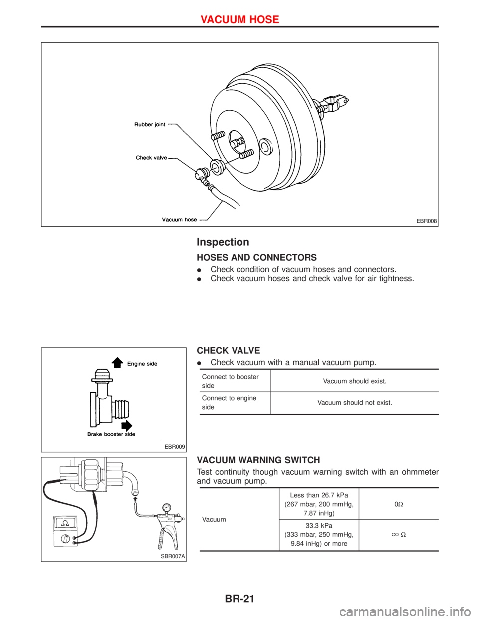
ICheck condition of vacuum hoses and connectors.
ICheck vacuum hoses and check valve for air tightness.
CHECK VALVE
ICheck vacuum with a manual vacuum pump.
Connect to booster
sideVacuum should exist.
Connect to engine
sideVacuum should not exist.
VACUUM WARNING SWITCH
Test continuity though vacuum warning switch with an ohmmeter
and vacuum pump.
VacuumLess than 26.7 kPa
(267 mbar, 200 mmHg,
7.87 inHg)0W
33.3 kPa
(333 mbar, 250 mmHg,
9.84 inHg) or more
W
EBR008
EBR009
SBR007A
VACUUM HOSE
BR-21
Page 234 of 1767
Removal
WARNING:
Clean brake lining with a vacuum dust collector.
CAUTION:
Make sure parking brake lever is released completely.
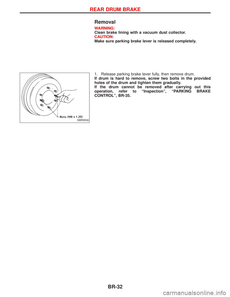
1. Release parking brake lever fully, then remove drum.
If drum is hard to remove, screw two bolts in the provided
holes of the drum and tighten them gradually.
If the drum cannot be removed after carrying out this
operation, refer to ªInspectionº, ªPARKING BRAKE
CONTROLº, BR-35.
SBR093A
REAR DRUM BRAKE
BR-32