2002 NISSAN TERRANO sunroof
[x] Cancel search: sunroofPage 289 of 1767
BODY & TRIM
SECTION
BT
CONTENTS
PRECAUTIONS...............................................................2
Service Notice..............................................................2
Supplemental Restraint System (SRS)²AIR
BAG²and²SEAT BELT PRE-TENSIONER²...............2
CLIP AND FASTENER....................................................3
Description ...................................................................3
CHASSIS AND BODY MAINTENANCE.........................5
Checking Body Corrosion ............................................5
BODY FRONT END.........................................................6
Removal and Installation .............................................6
BODY REAR END AND OPENER..................................8
Removal and Installation .............................................8
DOOR.............................................................................10
Removal and Installation ...........................................10
INSTRUMENT PANEL ASSEMBLY..............................16
Removal and Installation ...........................................16
SIDE AND FLOOR TRIM..............................................18
Removal and Installation ...........................................18
DOOR TRIM...................................................................19
Removal and Installation ...........................................19ROOF TRIM...................................................................20
Removal and Installation ...........................................20
EXTERIOR.....................................................................21
Removal and Installation ...........................................21
FRONT SEAT.................................................................34
Removal and Installation ...........................................34
Heated Seat ...............................................................36
Active Head Restraint ................................................36
SECOND SEAT..............................................................37
Removal and Installation ...........................................37
THIRD SEAT..................................................................39
Removal and Installation ...........................................39
SUNROOF......................................................................40
Removal and Installation ...........................................40
WINDSHIELD AND WINDOWS....................................42
Removal and Installation ...........................................42
DOOR MIRROR.............................................................48
Removal and Installation ...........................................48
BODY (ALIGNMENT)....................................................49
Alignment ...................................................................49
Page 293 of 1767
Checking Body Corrosion
Visually check the body sheet metal panel for corrosion, paint damage (scratches, chipping, rubbing, etc.) or
damage to the anti-corrosion materials. In particular, check the following locations.
Hemmed portion
Hood front end, door lower end, back door rear end, etc.
Panel joint
Side sill of rear fender and center pillar, rear wheel housing of rear fender, around strut tower in engine
compartment, etc.
Panel edge
Back door opening, sunroof opening, fender wheelarch flange, fuel filler lid flange, around holes in panel, etc.
Parts contact
Waist molding, windshield molding, bumper, etc.
Protectors
Damage or condition of mudguard, fender protector, chipping protector, etc.
Anti-corrosion materials
Damage or separation of anti-corrosion materials under the body.
Drain holes
Condition of drain holes at door and side sill.
When repairing corroded areas, refer to the Corrosion Repair Manual.
CHASSIS AND BODY MAINTENANCE
BT-5
Page 328 of 1767
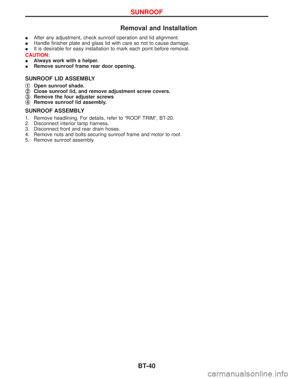
Removal and Installation
IAfter any adjustment, check sunroof operation and lid alignment.
IHandle finisher plate and glass lid with care so not to cause damage.
IIt is desirable for easy installation to mark each point before removal.
CAUTION:
IAlways work with a helper.
IRemove sunroof frame rear door opening.
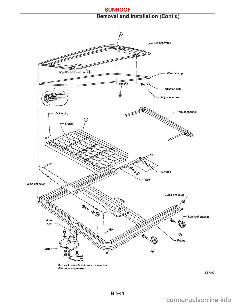
SUNROOF LID ASSEMBLY
q1Open sunroof shade.
q
2Close sunroof lid, and remove adjustment screw covers.
q
3Remove the four adjuster screws
q
4Remove sunroof lid assembly.
SUNROOF ASSEMBLY
1. Remove headlining. For details, refer to ªROOF TRIMº, BT-20.
2. Disconnect interior lamp harness.
3. Disconnect front and rear drain hoses.
4. Remove nuts and bolts securing sunroof frame and motor to roof.
5. Remove sunroof assembly.
SUNROOF
BT-40
Page 329 of 1767
EBF032
SUNROOF
Removal and Installation (Cont'd)
BT-41
Page 818 of 1767
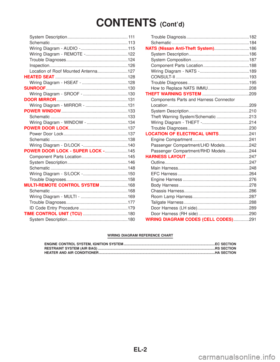
System Description .................................................. 111
Schematic ................................................................ 113
Wiring Diagram - AUDIO - ....................................... 115
Wiring Diagram - REMOTE -...................................122
Trouble Diagnoses...................................................124
Inspection.................................................................126
Location of Roof Mounted Antenna .........................127
HEATED SEAT............................................................128
Wiring Diagram - HSEAT - ......................................128
SUNROOF....................................................................130
Wiring Diagram - SROOF - .....................................130
DOOR MIRROR...........................................................131
Wiring Diagram - MIRROR - ...................................131
POWER WINDOW.......................................................133
Schematic ................................................................133
Wiring Diagram - WINDOW - ..................................134
POWER DOOR LOCK.................................................137
Power Door Lock .....................................................137
Schematic ................................................................138
Wiring Diagram - D/LOCK -.....................................140
POWER DOOR LOCK - SUPER LOCK -...................145
Component Parts Location ......................................145
System Description ..................................................146
Schematic ................................................................148
Wiring Diagram - S/LOCK - .....................................150
Trouble Diagnoses...................................................158
MULTI-REMOTE CONTROL SYSTEM.......................168
Schematic ................................................................168
Wiring Diagram - MULTI - .......................................169
Trouble Diagnoses...................................................177
ID Code Entry Procedure ........................................179
TIME CONTROL UNIT (TCU).....................................180
System Description ..................................................180Trouble Diagnosis ....................................................182
Schematic ................................................................184
NATS (Nissan Anti-Theft System).............................186
System Description ..................................................186
System Composition ................................................187
Component Parts Location ......................................188
Wiring Diagram - NATS -.........................................189
CONSULT-II .............................................................193
Trouble Diagnoses...................................................195
How to Replace NATS IMMU ..................................208
THEFT WARNING SYSTEM.......................................209
Components Parts and Harness Connector
Location ...................................................................209
System Description ..................................................210
Theft Warning System/Schematic ...........................213
Wiring Diagram - THEFT -.......................................214
Trouble Diagnoses...................................................230
LOCATION OF ELECTRICAL UNITS.........................241
Engine Compartment ...............................................241
Passenger Compartment/LHD Models ....................242
Passenger Compartment/RHD Models ...................244
HARNESS LAYOUT....................................................247
Outline......................................................................247
Main Harness...........................................................248
EFC Harness ...........................................................264
Engine Harness .......................................................276
Body Harness ..........................................................278
Chassis Harness......................................................286
Room Lamp Harness...............................................287
Tailgate Harness ......................................................288
Door Harness (LH side)...........................................289
Door Harness (RH side) ..........................................290
WIRING DIAGRAM CODES (CELL CODES).............291
WIRING DIAGRAM REFERENCE CHART
ENGINE CONTROL SYSTEM, IGNITION SYSTEM ................................................................................................EC SECTION
RESTRAINT SYSTEM (AIR BAG) ...........................................................................................................................RS SECTION
HEATER AND AIR CONDITIONER ..........................................................................................................................HA SECTION
CONTENTS(Cont'd)
EL-2
Page 946 of 1767
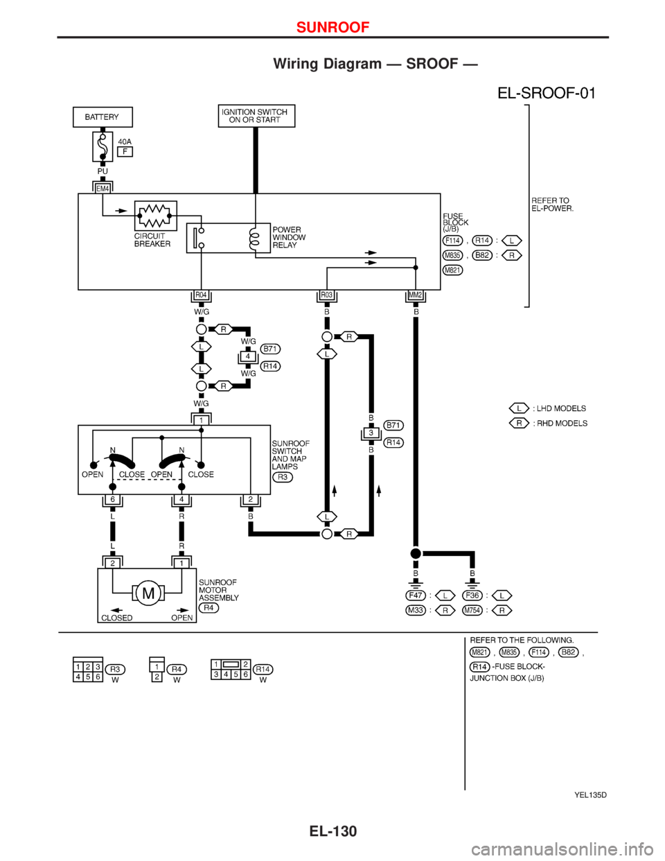
Wiring Diagram Ð SROOF Ð
YEL135D
SUNROOF
EL-130
Page 1108 of 1767
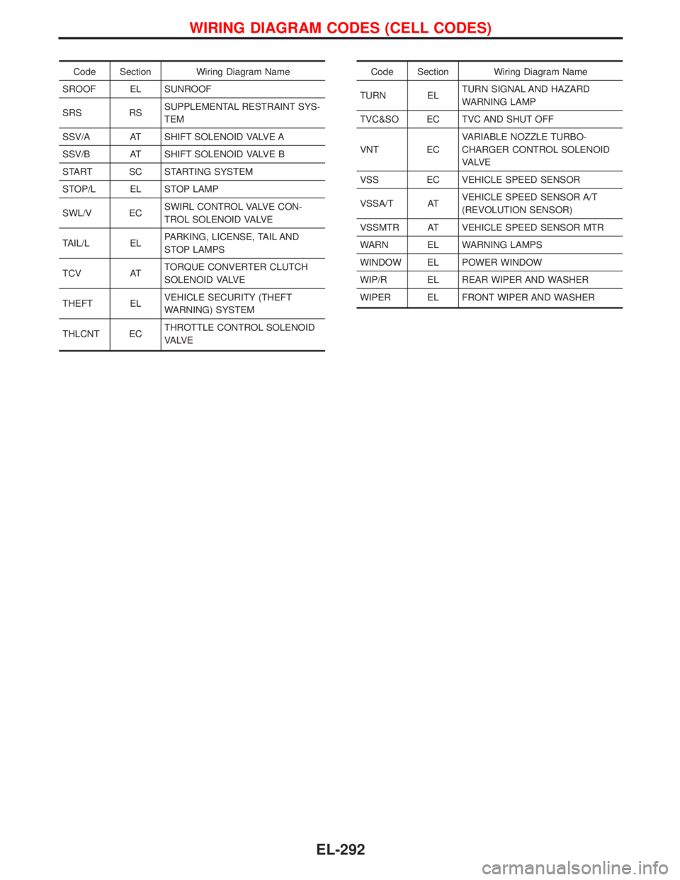
Code Section Wiring Diagram Name
SROOF EL SUNROOF
SRS RSSUPPLEMENTAL RESTRAINT SYS-
TEM
SSV/A AT SHIFT SOLENOID VALVE A
SSV/B AT SHIFT SOLENOID VALVE B
START SC STARTING SYSTEM
STOP/L EL STOP LAMP
SWL/V ECSWIRL CONTROL VALVE CON-
TROL SOLENOID VALVE
TAIL/L ELPARKING, LICENSE, TAIL AND
STOP LAMPS
TCV ATTORQUE CONVERTER CLUTCH
SOLENOID VALVE
THEFT ELVEHICLE SECURITY (THEFT
WARNING) SYSTEM
THLCNT ECTHROTTLE CONTROL SOLENOID
VA LV ECode Section Wiring Diagram Name
TURN ELTURN SIGNAL AND HAZARD
WARNING LAMP
TVC&SO EC TVC AND SHUT OFF
VNT ECVARIABLE NOZZLE TURBO-
CHARGER CONTROL SOLENOID
VA LV E
VSS EC VEHICLE SPEED SENSOR
VSSA/T ATVEHICLE SPEED SENSOR A/T
(REVOLUTION SENSOR)
VSSMTR AT VEHICLE SPEED SENSOR MTR
WARN EL WARNING LAMPS
WINDOW EL POWER WINDOW
WIP/R EL REAR WIPER AND WASHER
WIPER EL FRONT WIPER AND WASHER
WIRING DIAGRAM CODES (CELL CODES)
EL-292
Page 1423 of 1767
Pre-delivery inspection.....................................MA-3
Priming pump .................................................EC-50
Propeller shaft ............................................PD-5, 57
Propeller shaft greasing...........................MA-36, 38
Propeller shaft inspection ........................MA-36, 38
Propeller shaft on vehicle service ....................PD-6
Pump communication line (Electronic
Fuel Injection Pump) ................................EC-175
Pump control module (Electronic Fuel
Injection Pump).........................................EC-189
R
Radiator ....................................................LC-14, 32
Rear axle................................................RA-4, 6, 12
Rear bumper .....................................................BT-8
Rear case (Transfer)...................................TF-9, 24
Rear combination lamp removal and
installation .....................................................BT-8
Rear door ........................................................BT-12
Rear door trim...........................................BT-18, 19
Rear drum brake ............................................BR-31
Rear fog lamp .................................................EL-54
Rear side window .....................................BT-21, 43
Rear suspension ........................................RA-4, 12
Rear window defogger..................EL-107, 109, 110
Refrigerant connection precaution ...................HA-4
Refrigerant general precaution.........................HA-3
Refrigerant lines .............................................HA-17
Refrigeration cycle............................................HA-9
REMOTE - Wiring diagram ...........................EL-122
Removal and installation (A/T) ......................AT-116
Removal and installation (Transfer) ..................TF-7
Reverse clutch ..............................................AT-151
Reverse idler shaft (M/T)................................MT-11
Reverse main gear (M/T) ...............................MT-11
Revolution sensor (A/T) ..........................AT-50, 114
R/FOG - Wiring diagram .................................EL-54
Ring gear diff. inspection .........................PD-20, 42
Rocker cover ..................................................EM-20
Roof trim .........................................................BT-20
Rotor disc (front) .............................................FA-18
S
Screw jack .......................................................GI-32
Seal - See Exterior .........................................BT-21
Seat belt inspection .................................MA-36, 45
Seat belt pre-tensioner.................................RS-2, 9
Seat belt pre-tensioner disposal ....................RS-20
Seat belt, front ..................................................RS-4
Seat, front .......................................................BT-34
Seat, second (2nd) .........................................BT-37
Seat, third (3rd) ...............................................BT-39
Second (2nd) seat ..........................................BT-37
Self-diagnostic results ............................EC-35, 324
Shift control (Transfer) ..............................TF-11, 24Shift control components
(M/T) ............................MT-13, 14, 15, 21, 23, 31
Shift fork (M/T) ...............................................MT-13
Shift schedule................................................AT-196
Shift solenoid valve A (A/T).............................AT-63
Shift solenoid valve B (A/T) ............................AT-66
Shock absorber (front) ....................................FA-30
Shock absorber (rear) ..............................RA-14, 16
Side air bag ....................................................RS-18
Side air bag (satellite) sensor ........................RS-13
Side bearing preload diff. ...............................PD-24
Side trim....................................................BT-18, 21
Side window - See Rear side window ............BT-21
S/LOCK - Wiring diagram .............................EL-150
SMJ (super multiple junction) .......................Foldout
Speedometer...................................................EL-72
Spill valve .....................................................EC-182
Spiral cable.....................................................RS-14
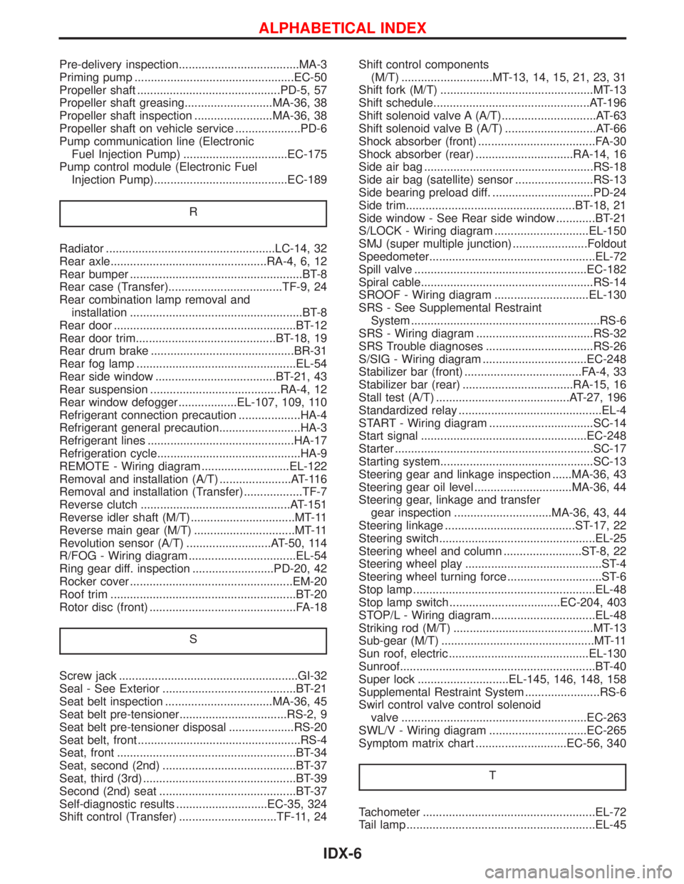
SROOF - Wiring diagram .............................EL-130
SRS - See Supplemental Restraint
System ..........................................................RS-6
SRS - Wiring diagram ....................................RS-32
SRS Trouble diagnoses .................................RS-26
S/SIG - Wiring diagram ................................EC-248
Stabilizer bar (front) ....................................FA-4, 33
Stabilizer bar (rear) ..................................RA-15, 16
Stall test (A/T) .........................................AT-27, 196
Standardized relay ............................................EL-4
START - Wiring diagram ................................SC-14
Start signal ...................................................EC-248
Starter .............................................................SC-17
Starting system...............................................SC-13
Steering gear and linkage inspection ......MA-36, 43
Steering gear oil level ..............................MA-36, 44
Steering gear, linkage and transfer
gear inspection ..............................MA-36, 43, 44
Steering linkage ........................................ST-17, 22
Steering switch................................................EL-25
Steering wheel and column ........................ST-8, 22
Steering wheel play ..........................................ST-4
Steering wheel turning force .............................ST-6
Stop lamp ........................................................EL-48
Stop lamp switch ..................................EC-204, 403
STOP/L - Wiring diagram................................EL-48
Striking rod (M/T) ...........................................MT-13
Sub-gear (M/T) ...............................................MT-11
Sun roof, electric ...........................................EL-130
Sunroof............................................................BT-40
Super lock ............................EL-145, 146, 148, 158
Supplemental Restraint System .......................RS-6
Swirl control valve control solenoid
valve .........................................................EC-263
SWL/V - Wiring diagram ..............................EC-265
Symptom matrix chart ............................EC-56, 340
T
Tachometer .....................................................EL-72
Tail lamp ..........................................................EL-45
ALPHABETICAL INDEX
IDX-6