2002 NISSAN TERRANO time control
[x] Cancel search: time controlPage 16 of 1767
Self-diagnosis
After performing this procedure, place check marks for results on
the ªDIAGNOSTIC WORKSHEETº, AT-24. Reference pages are
provided following the items.
SELF-DIAGNOSTIC PROCEDURE (With CONSULT-II)
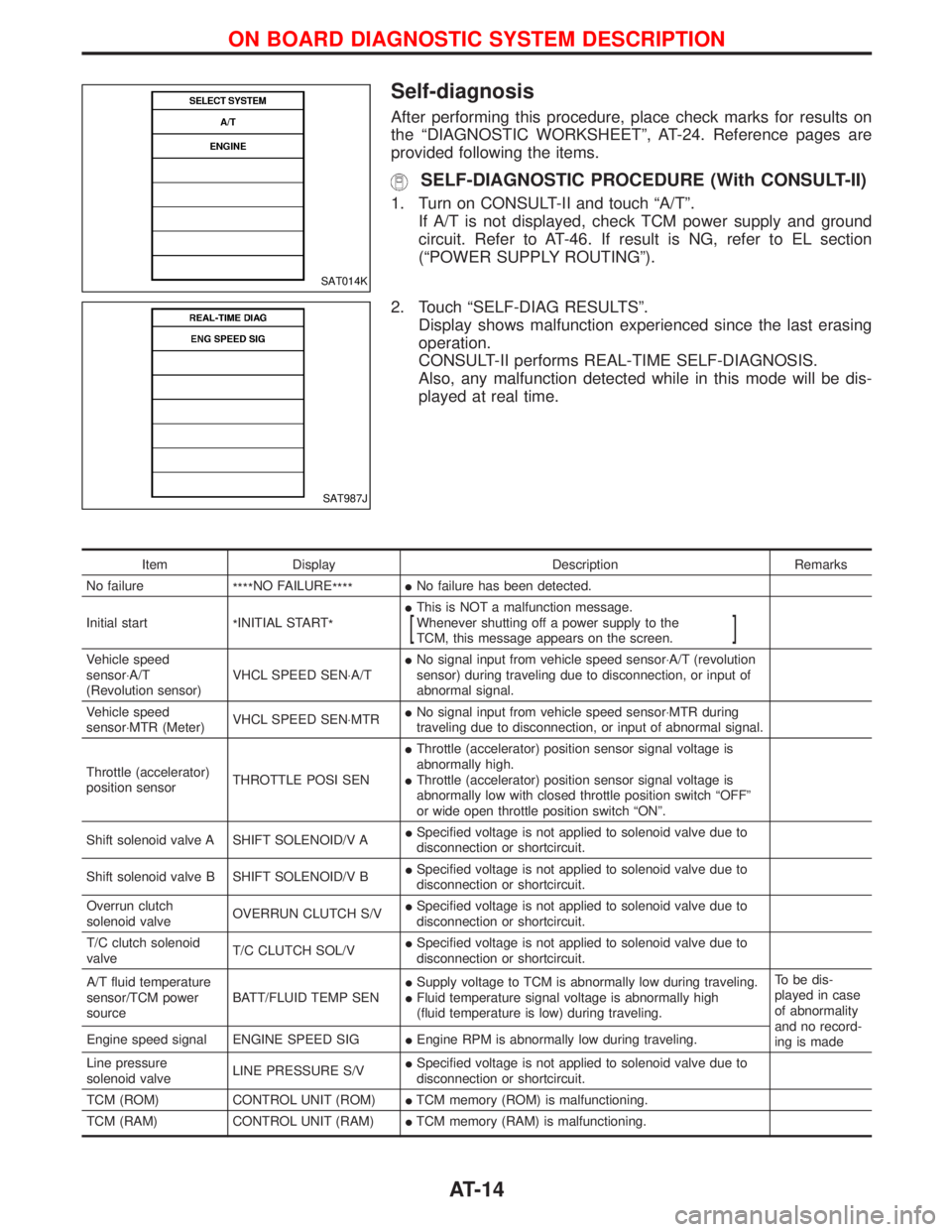
1. Turn on CONSULT-II and touch ªA/Tº.
If A/T is not displayed, check TCM power supply and ground
circuit. Refer to AT-46. If result is NG, refer to EL section
(ªPOWER SUPPLY ROUTINGº).
2. Touch ªSELF-DIAG RESULTSº.
Display shows malfunction experienced since the last erasing
operation.
CONSULT-II performs REAL-TIME SELF-DIAGNOSIS.
Also, any malfunction detected while in this mode will be dis-
played at real time.
Item Display Description Remarks
No failure
****NO FAILURE
****INo failure has been detected.
Initial start
*INITIAL START
*IThis is NOT a malfunction message.
Whenever shutting off a power supply to the
TCM, this message appears on the screen.
[]
Vehicle speed
sensor×A/T
(Revolution sensor)VHCL SPEED SEN×A/TINo signal input from vehicle speed sensor×A/T (revolution
sensor) during traveling due to disconnection, or input of
abnormal signal.
Vehicle speed
sensor×MTR (Meter)VHCL SPEED SEN×MTRINo signal input from vehicle speed sensor×MTR during
traveling due to disconnection, or input of abnormal signal.
Throttle (accelerator)
position sensorTHROTTLE POSI SENIThrottle (accelerator) position sensor signal voltage is
abnormally high.
IThrottle (accelerator) position sensor signal voltage is
abnormally low with closed throttle position switch ªOFFº
or wide open throttle position switch ªONº.
Shift solenoid valve A SHIFT SOLENOID/V AISpecified voltage is not applied to solenoid valve due to
disconnection or shortcircuit.
Shift solenoid valve B SHIFT SOLENOID/V BISpecified voltage is not applied to solenoid valve due to
disconnection or shortcircuit.
Overrun clutch
solenoid valveOVERRUN CLUTCH S/VISpecified voltage is not applied to solenoid valve due to
disconnection or shortcircuit.
T/C clutch solenoid
valveT/C CLUTCH SOL/VISpecified voltage is not applied to solenoid valve due to
disconnection or shortcircuit.
A/T fluid temperature
sensor/TCM power
sourceBATT/FLUID TEMP SENISupply voltage to TCM is abnormally low during traveling.
IFluid temperature signal voltage is abnormally high
(fluid temperature is low) during traveling.To be dis-
played in case
of abnormality
and no record-
ing is made Engine speed signal ENGINE SPEED SIGIEngine RPM is abnormally low during traveling.
Line pressure
solenoid valveLINE PRESSURE S/VISpecified voltage is not applied to solenoid valve due to
disconnection or shortcircuit.
TCM (ROM) CONTROL UNIT (ROM)ITCM memory (ROM) is malfunctioning.
TCM (RAM) CONTROL UNIT (RAM)ITCM memory (RAM) is malfunctioning.
SAT014K
SAT987J
ON BOARD DIAGNOSTIC SYSTEM DESCRIPTION
AT-14
Page 20 of 1767
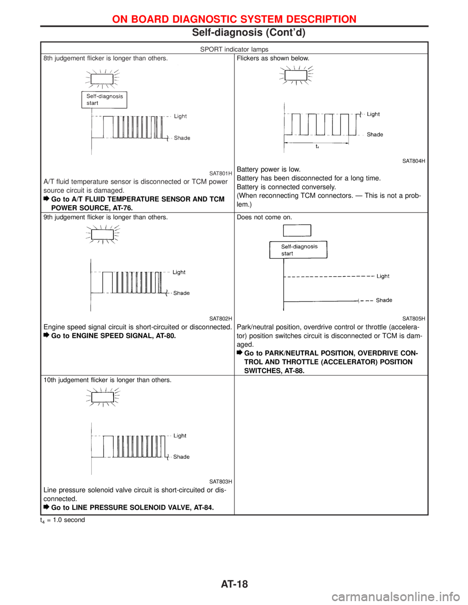
SPORT indicator lamps
8th judgement flicker is longer than others.
SAT801H
A/T fluid temperature sensor is disconnected or TCM power
source circuit is damaged.
Go to A/T FLUID TEMPERATURE SENSOR AND TCM
POWER SOURCE, AT-76.
Flickers as shown below.
SAT804H
Battery power is low.
Battery has been disconnected for a long time.
Battery is connected conversely.
(When reconnecting TCM connectors. Ð This is not a prob-
lem.)
9th judgement flicker is longer than others.
SAT802H
Engine speed signal circuit is short-circuited or disconnected.
Go to ENGINE SPEED SIGNAL, AT-80.
Does not come on.
SAT805H
Park/neutral position, overdrive control or throttle (accelera-
tor) position switches circuit is disconnected or TCM is dam-
aged.
Go to PARK/NEUTRAL POSITION, OVERDRIVE CON-
TROL AND THROTTLE (ACCELERATOR) POSITION
SWITCHES, AT-88.
10th judgement flicker is longer than others.
SAT803H
Line pressure solenoid valve circuit is short-circuited or dis-
connected.
Go to LINE PRESSURE SOLENOID VALVE, AT-84.
t4= 1.0 second
ON BOARD DIAGNOSTIC SYSTEM DESCRIPTION
Self-diagnosis (Cont'd)
AT-18
Page 22 of 1767
Diagnosis by CONSULT-II
NOTICE
1. The CONSULT-II electrically displays shift timing and lock-up timing (that is, operation timing of each
solenoid).
Check for time difference between actual shift timing and the CONSULT-II display. If the difference is
noticeable, mechanical parts (except solenoids, sensors, etc.) may be malfunctioning. Check mechanical
parts using applicable diagnostic procedures.
2. Shift schedule (which implies gear position) displayed on CONSULT-II and that indicated in Service Manual
may differ slightly. This occurs because of the following reasons:
IActual shift schedule has more or less tolerance or allowance,
IShift schedule indicated in Service Manual refers to the point where shifts start. Gear position displayed
on CONSULT-II indicates the point where shifts are completed.
3. Shift solenoid valve ªAº or ªBº is displayed on CONSULT-II at the start of shifting. Gear position is displayed
upon completion of shifting (which is computed by TCM).
4. Additional CONSULT-II information can be found in the Operation Manual supplied with the CONSULT-II
unit.
SELF-DIAGNOSTIC RESULT TEST MODE
Refer to AT-14.
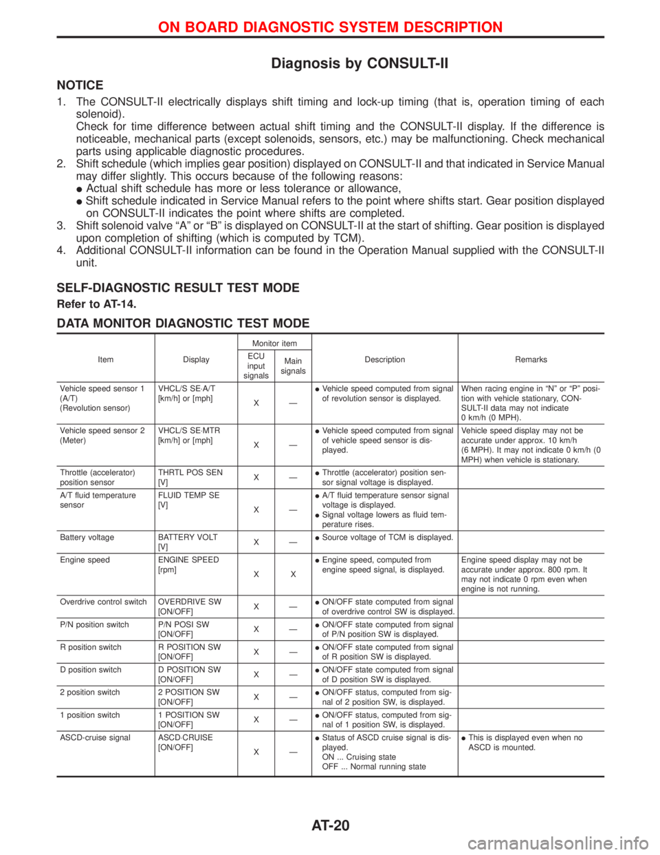
DATA MONITOR DIAGNOSTIC TEST MODE
Item DisplayMonitor item
Description Remarks ECU
input
signalsMain
signals
Vehicle speed sensor 1
(A/T)
(Revolution sensor)VHCL/S SE×A/T
[km/h] or [mph]
XÐIVehicle speed computed from signal
of revolution sensor is displayed.When racing engine in ªNº or ªPº posi-
tion with vehicle stationary, CON-
SULT-II data may not indicate
0 km/h (0 MPH).
Vehicle speed sensor 2
(Meter)VHCL/S SE×MTR
[km/h] or [mph]
XÐIVehicle speed computed from signal
of vehicle speed sensor is dis-
played.Vehicle speed display may not be
accurate under approx. 10 km/h
(6 MPH). It may not indicate 0 km/h (0
MPH) when vehicle is stationary.
Throttle (accelerator)
position sensorTHRTL POS SEN
[V]XÐIThrottle (accelerator) position sen-
sor signal voltage is displayed.
A/T fluid temperature
sensorFLUID TEMP SE
[V]
XÐIA/T fluid temperature sensor signal
voltage is displayed.
ISignal voltage lowers as fluid tem-
perature rises.
Battery voltage BATTERY VOLT
[V]XÐISource voltage of TCM is displayed.
Engine speed ENGINE SPEED
[rpm]
XXIEngine speed, computed from
engine speed signal, is displayed.Engine speed display may not be
accurate under approx. 800 rpm. It
may not indicate 0 rpm even when
engine is not running.
Overdrive control switch OVERDRIVE SW
[ON/OFF]XÐION/OFF state computed from signal
of overdrive control SW is displayed.
P/N position switch P/N POSI SW
[ON/OFF]XÐION/OFF state computed from signal
of P/N position SW is displayed.
R position switch R POSITION SW
[ON/OFF]XÐION/OFF state computed from signal
of R position SW is displayed.
D position switch D POSITION SW
[ON/OFF]XÐION/OFF state computed from signal
of D position SW is displayed.
2 position switch 2 POSITION SW
[ON/OFF]XÐION/OFF status, computed from sig-
nal of 2 position SW, is displayed.
1 position switch 1 POSITION SW
[ON/OFF]XÐION/OFF status, computed from sig-
nal of 1 position SW, is displayed.
ASCD-cruise signal ASCD×CRUISE
[ON/OFF]
XÐIStatus of ASCD cruise signal is dis-
played.
ON ... Cruising state
OFF ... Normal running stateIThis is displayed even when no
ASCD is mounted.
ON BOARD DIAGNOSTIC SYSTEM DESCRIPTION
AT-20
Page 237 of 1767
Removal and Installation
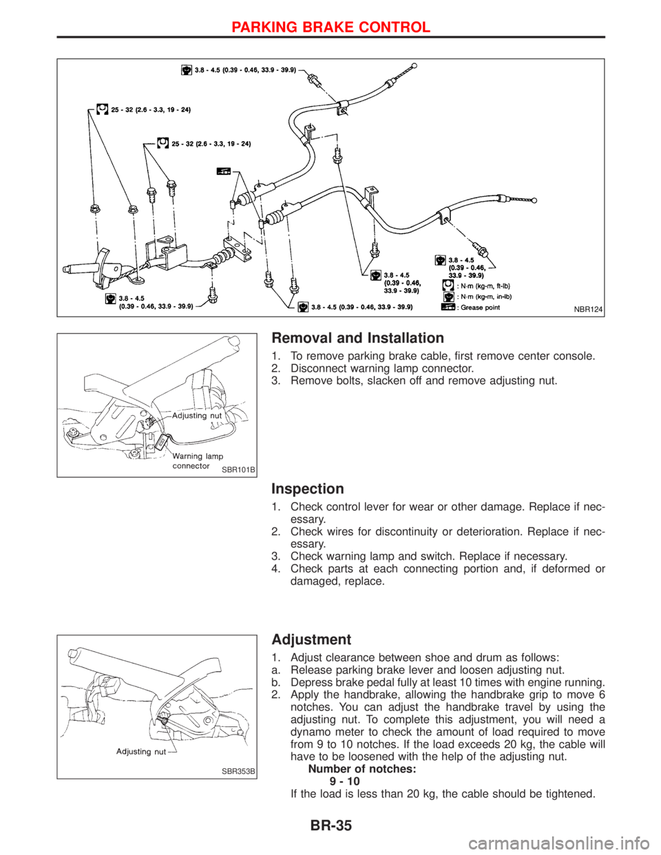
1. To remove parking brake cable, first remove center console.
2. Disconnect warning lamp connector.
3. Remove bolts, slacken off and remove adjusting nut.
Inspection
1. Check control lever for wear or other damage. Replace if nec-
essary.
2. Check wires for discontinuity or deterioration. Replace if nec-
essary.
3. Check warning lamp and switch. Replace if necessary.
4. Check parts at each connecting portion and, if deformed or
damaged, replace.
Adjustment
1. Adjust clearance between shoe and drum as follows:
a. Release parking brake lever and loosen adjusting nut.
b. Depress brake pedal fully at least 10 times with engine running.
2. Apply the handbrake, allowing the handbrake grip to move 6
notches. You can adjust the handbrake travel by using the
adjusting nut. To complete this adjustment, you will need a
dynamo meter to check the amount of load required to move
from 9 to 10 notches. If the load exceeds 20 kg, the cable will
have to be loosened with the help of the adjusting nut.
Number of notches:
9-10
If the load is less than 20 kg, the cable should be tightened.
NBR124
SBR101B
SBR353B
PARKING BRAKE CONTROL
BR-35
Page 239 of 1767
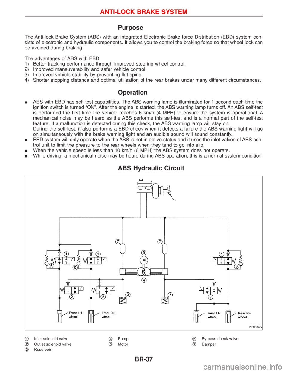
Purpose
The Anti-lock Brake System (ABS) with an integrated Electronic Brake force Distribution (EBD) system con-
sists of electronic and hydraulic components. It allows you to control the braking force so that wheel lock can
be avoided during braking.
The advantages of ABS with EBD
1) Better tracking performance through improved steering wheel control.
2) Improved maneuverability and safer vehicle control.
3) Improved vehicle stability by preventing flat spins.
4) Shorter stopping distance and optimal utilisation of the rear brakes under many different circumstances.
Operation
IABS with EBD has self-test capabilities. The ABS warning lamp is illuminated for 1 second each time the
ignition switch is turned ªONº. After the engine is started, the ABS warning lamp turns off. An ABS self-test
is performed the first time the vehicle reaches 6 km/h (4 MPH) to ensure the system is operational. A
mechanical noise may be heard as the ABS performs this self-test and is a normal part of the self-test
feature. If a malfunction is detected during this check, the ABS warning lamp will stay on.
During the self-test, it also performs a EBD check when it detects a failure the ABS warning light will go
on simultaneously with the brake warning light and an audible sound will sound constantly.
IEBD system will only operate when the ABS is not in active status and it uses the inlet valves of ABS con-
trol unit to limit the pressure to the rear wheels when they tend to go into slip.
IWhen the vehicle speed is less than 10 km/h (6 MPH) the ABS system does not operate.
IWhile driving, a mechanical noise may be heard during ABS operation, this is a normal system condition.
ABS Hydraulic Circuit
q1Inlet solenoid valve
q
2Outlet solenoid valve
q
3Reservoirq
4Pump
q
5Motorq
6By pass check valve
q
7Damper
NBR346
ANTI-LOCK BRAKE SYSTEM
BR-37
Page 261 of 1767
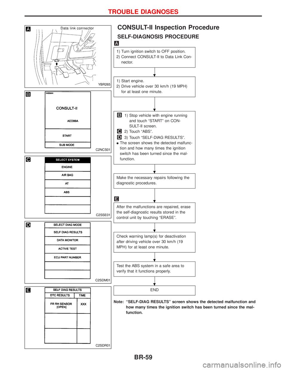
CONSULT-II Inspection Procedure
SELF-DIAGNOSIS PROCEDURE
1) Turn ignition switch to OFF position.
2) Connect CONSULT-II to Data Link Con-
nector.
1) Start engine.
2) Drive vehicle over 30 km/h (19 MPH)
for at least one minute.
1) Stop vehicle with engine running
and touch ªSTARTº on CON-
SULT-II screen.
2) Touch ªABSº.
3) Touch ªSELF-DIAG RESULTSº.
IThe screen shows the detected malfunc-
tion and how many times the ignition
switch has been turned since the mal-
function.
Make the necessary repairs following the
diagnostic procedures.
After the malfunctions are repaired, erase
the self-diagnostic results stored in the
control unit by touching ªERASEº.
Check warning lamp(s) for deactivation
after driving vehicle over 30 km/h (19
MPH) for at least one minute.
Test the ABS system in a safe area to
verify that it functions properly.
END
Note: ªSELF-DIAG RESULTSº screen shows the detected malfunction and
how many times the ignition switch has been turned since the mal-
function.
YBR265
C2NCS01
C2SSE01
C2SDM01
C2SDR01
H
H
H
H
H
H
H
TROUBLE DIAGNOSES
BR-59
Page 383 of 1767
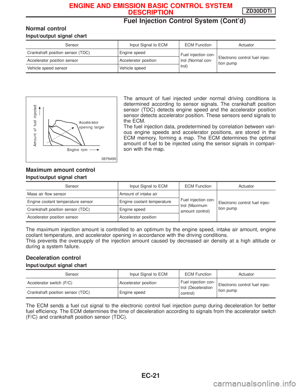
Normal control
Input/output signal chart
Sensor Input Signal to ECM ECM Function Actuator
Crankshaft position sensor (TDC) Engine speed
Fuel injection con-
trol (Normal con-
trol)Electronic control fuel injec-
tion pump Accelerator position sensor Accelerator position
Vehicle speed sensor Vehicle speed
The amount of fuel injected under normal driving conditions is
determined according to sensor signals. The crankshaft position
sensor (TDC) detects engine speed and the accelerator position
sensor detects accelerator position. These sensors send signals to
the ECM.
The fuel injection data, predetermined by correlation between vari-
ous engine speeds and accelerator positions, are stored in the
ECM memory, forming a map. The ECM determines the optimal
amount of fuel to be injected using the sensor signals in compari-
son with the map.
Maximum amount control
Input/output signal chart
Sensor Input Signal to ECM ECM Function Actuator
Mass air flow sensor Amount of intake air
Fuel injection con-
trol (Maximum
amount control)Electronic control fuel injec-
tion pump Engine coolant temperature sensor Engine coolant temperature
Crankshaft position sensor (TDC) Engine speed
Accelerator position sensor Accelerator position
The maximum injection amount is controlled to an optimum by the engine speed, intake air amount, engine
coolant temperature, and accelerator opening in accordance with the driving conditions.
This prevents the oversupply of the injection amount caused by decreased air density at a high altitude or
during a system failure.
Deceleration control
Input/output signal chart
Sensor Input Signal to ECM ECM Function Actuator
Accelerator switch (F/C) Accelerator positionFuel injection con-
trol (Deceleration
control)Electronic control fuel injec-
tion pump
Crankshaft position sensor (TDC) Engine speed
The ECM sends a fuel cut signal to the electronic control fuel injection pump during deceleration for better
fuel efficiency. The ECM determines the time of deceleration according to signals from the accelerator switch
(F/C) and crankshaft position sensor (TDC).
SEF649S
ENGINE AND EMISSION BASIC CONTROL SYSTEM
DESCRIPTIONZD30DDTi
Fuel Injection Control System (Cont'd)
EC-21
Page 384 of 1767
Fuel Injection Timing Control System
DESCRIPTION
The target fuel injection timing in accordance with the engine speed and the fuel injection amount are recorded
as a map in the ECM beforehand. The ECM and the injection pump control unit exchange signals and per-
form feedback control for optimum injection timing in accordance with the map.
Air Conditioning Cut Control
DESCRIPTION
Input/output signal chart
Sensor Input Signal to ECM ECM Function Actuator
Air conditioner switch Air conditioner ªONº signal
Air conditioner cut
controlAir conditioner relay Accelerator position sensorAccelerator valve opening
angle
Vehicle speed sensor Vehicle speed
Engine coolant temperature sensor Engine coolant temperature
System description
This system improves acceleration when the air conditioner is used.
When the accelerator pedal is fully depressed, the air conditioner is turned off for a few seconds.
When engine coolant temperature becomes excessively high, the air conditioner is turned off. This continues
until the engine coolant temperature returns to normal.
Fuel Cut Control (at no load & high engine
speed)
DESCRIPTION
Input/output signal chart
Sensor Input Signal to ECM ECM Function Actuator
Vehicle speed sensor Vehicle speed
Fuel cut controlElectronic control fuel injec-
tion pump Park/Neutral position (PNP) switch Neutral position
Accelerator position switch or Accelerator
switch (F/C)Accelerator position
Engine coolant temperature sensor Engine coolant temperature
Crankshaft position sensor (TDC) Engine speed
If the engine speed is above 2,700 rpm with no load (for example, in neutral and engine speed over 2,700
rpm) fuel will be cut off after some time. The exact time when the fuel is cut off varies based on engine speed.
Fuel cut will operate until the engine speed reaches 1,500 rpm, then fuel cut is cancelled.
NOTE:
This function is different from deceleration control listed under ªFuel Injection Control Systemº, EC-20.
ENGINE AND EMISSION BASIC CONTROL SYSTEM
DESCRIPTIONZD30DDTi
EC-22