Page 115 of 1767
Control Valve Assembly and Accumulators
REMOVAL
1. Remove exhaust front tube.
2. Remove oil pan and gasket and drain ATF.
3. Remove A/T fluid temperature sensor if necessary.
4. Remove oil strainer.
5. Remove control valve assembly by removing fixing bolts and
disconnecting harness connector.
Bolt length and location
Bolt symbolmm (in)
qA33 (1.30)
q
B45 (1.77)
6. Remove solenoids and valves from valve body if necessary.
7. Remove terminal cord assembly if necessary.
8. Remove accumulatorq
A,qB,qCandqDby applying compressed
air if necessary.
IHold each piston with rag.
9. Reinstall any part removed.
IAlways use new sealing parts.
NAT277
SAT073BA
SAT353B
SAT074BA
ON-VEHICLE SERVICE
AT-113
Page 195 of 1767
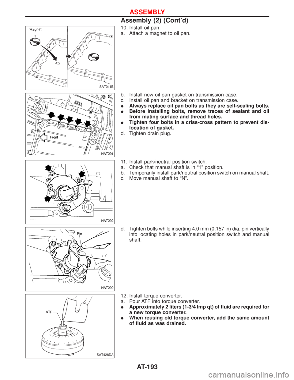
10. Install oil pan.
a. Attach a magnet to oil pan.
b. Install new oil pan gasket on transmission case.
c. Install oil pan and bracket on transmission case.
IAlways replace oil pan bolts as they are self-sealing bolts.
IBefore installing bolts, remove traces of sealant and oil
from mating surface and thread holes.
ITighten four bolts in a criss-cross pattern to prevent dis-
location of gasket.
d. Tighten drain plug.
11. Install park/neutral position switch.
a. Check that manual shaft is in ª1º position.
b. Temporarily install park/neutral position switch on manual shaft.
c. Move manual shaft to ªNº.
d. Tighten bolts while inserting 4.0 mm (0.157 in) dia. pin vertically
into locating holes in park/neutral position switch and manual
shaft.
12. Install torque converter.
a. Pour ATF into torque converter.
IApproximately 2 liters (1-3/4 Imp qt) of fluid are required for
a new torque converter.
IWhen reusing old torque converter, add the same amount
of fluid as was drained.
SAT011B
NAT291
NAT292
NAT290
SAT428DA
ASSEMBLY
Assembly (2) (Cont'd)
AT-193
Page 211 of 1767
Removal
CAUTION:
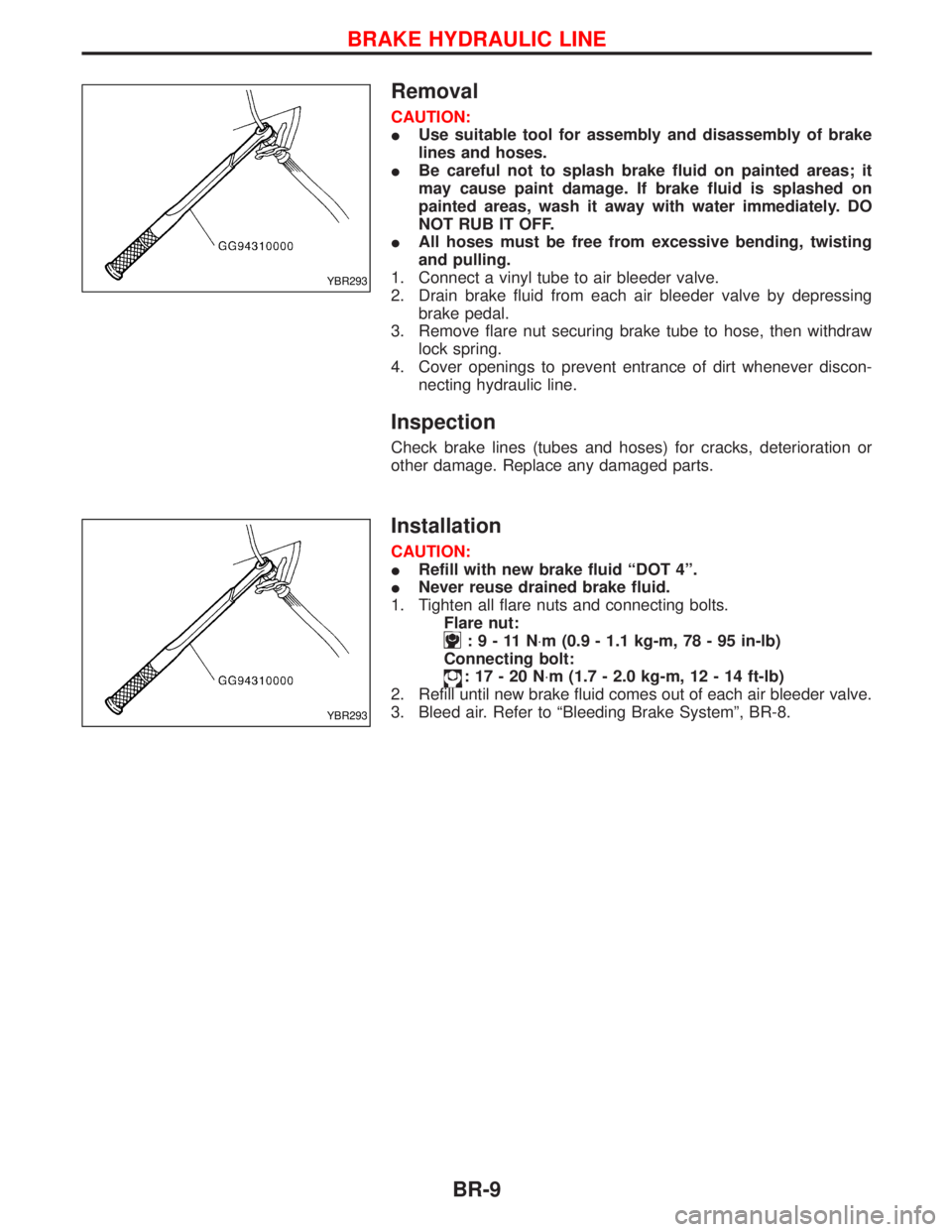
IUse suitable tool for assembly and disassembly of brake
lines and hoses.
IBe careful not to splash brake fluid on painted areas; it
may cause paint damage. If brake fluid is splashed on
painted areas, wash it away with water immediately. DO
NOT RUB IT OFF.
IAll hoses must be free from excessive bending, twisting
and pulling.
1. Connect a vinyl tube to air bleeder valve.
2. Drain brake fluid from each air bleeder valve by depressing
brake pedal.
3. Remove flare nut securing brake tube to hose, then withdraw
lock spring.
4. Cover openings to prevent entrance of dirt whenever discon-
necting hydraulic line.
Inspection
Check brake lines (tubes and hoses) for cracks, deterioration or
other damage. Replace any damaged parts.
Installation
CAUTION:
IRefill with new brake fluid ªDOT 4º.
INever reuse drained brake fluid.
1. Tighten all flare nuts and connecting bolts.
Flare nut:
:9-11N×m (0.9 - 1.1 kg-m, 78 - 95 in-lb)
Connecting bolt:
:17-20N×m (1.7 - 2.0 kg-m, 12 - 14 ft-lb)
2. Refill until new brake fluid comes out of each air bleeder valve.
3. Bleed air. Refer to ªBleeding Brake Systemº, BR-8.
YBR293
YBR293
BRAKE HYDRAULIC LINE
BR-9
Page 213 of 1767
Removal
CAUTION:
IBe careful not to splash brake fluid on painted areas; it
may cause paint damage. If brake fluid is splashed on
painted areas, wash it away with water immediately. DO
NOT RUB IT OFF.
IRemove flare nuts and LSV bolts.
Installation
CAUTION:
IRefill with new brake fluid ªDOT 4º.
INever reuse drained brake fluid.
ICheck level in brake fluid reservoir.
1. Tighten provisionally flare nuts.
2. Tighten LSV bolts.
:20-24N×m (2.0 - 2.4 kg-m, 14 - 17 ft-lb)
3. Tighten flare nuts.
:15-18N×m (1.5 - 1.8 kg-m, 11 - 13 ft-lb)
4. Bleed air. Refer to ªBleeding Brake Systemº, ªBRAKE
HYDRAULIC LINEº, BR-8.
5. Adjust load sensing valve (LSV). Refer to ªInspection and
Adjustmentº, ªLOAD SENSING VALVEº, BR-12.
YBR293
LOAD SENSING VALVE
BR-11
Page 220 of 1767
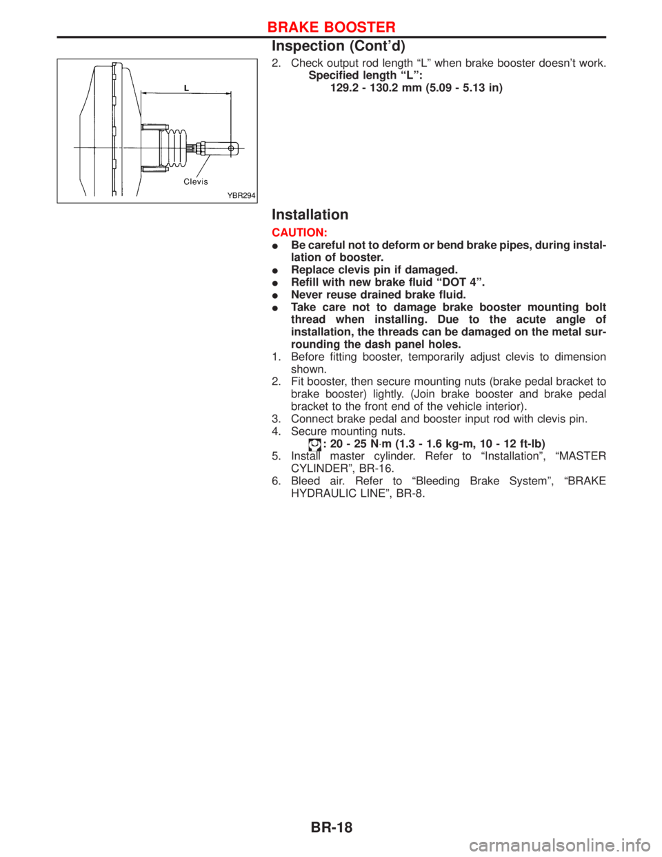
2. Check output rod length ªLº when brake booster doesn't work.
Specified length ªLº:
129.2 - 130.2 mm (5.09 - 5.13 in)
Installation
CAUTION:
IBe careful not to deform or bend brake pipes, during instal-
lation of booster.
IReplace clevis pin if damaged.
IRefill with new brake fluid ªDOT 4º.
INever reuse drained brake fluid.
ITake care not to damage brake booster mounting bolt
thread when installing. Due to the acute angle of
installation, the threads can be damaged on the metal sur-
rounding the dash panel holes.
1. Before fitting booster, temporarily adjust clevis to dimension
shown.
2. Fit booster, then secure mounting nuts (brake pedal bracket to
brake booster) lightly. (Join brake booster and brake pedal
bracket to the front end of the vehicle interior).
3. Connect brake pedal and booster input rod with clevis pin.
4. Secure mounting nuts.
:20-25N×m (1.3 - 1.6 kg-m, 10 - 12 ft-lb)
5. Install master cylinder. Refer to ªInstallationº, ªMASTER
CYLINDERº, BR-16.
6. Bleed air. Refer to ªBleeding Brake Systemº, ªBRAKE
HYDRAULIC LINEº, BR-8.
YBR294
BRAKE BOOSTER
Inspection (Cont'd)
BR-18
Page 328 of 1767
Removal and Installation
IAfter any adjustment, check sunroof operation and lid alignment.
IHandle finisher plate and glass lid with care so not to cause damage.
IIt is desirable for easy installation to mark each point before removal.
CAUTION:
IAlways work with a helper.
IRemove sunroof frame rear door opening.
SUNROOF LID ASSEMBLY
q1Open sunroof shade.
q
2Close sunroof lid, and remove adjustment screw covers.
q
3Remove the four adjuster screws
q
4Remove sunroof lid assembly.
SUNROOF ASSEMBLY
1. Remove headlining. For details, refer to ªROOF TRIMº, BT-20.
2. Disconnect interior lamp harness.
3. Disconnect front and rear drain hoses.
4. Remove nuts and bolts securing sunroof frame and motor to roof.
5. Remove sunroof assembly.
SUNROOF
BT-40
Page 390 of 1767
REMOVAL
1. Remove the following:
IEngine coolant draining
ICharge air cooler
IAir inlet pipe
IThrottle body
IRocker cover
IOil level gauge guide
IEGR cooler
IEGR guide tube
IEGR volume control solenoid valve
IFuel hose
IInjection tube
IRadiator upper hose
IRadiator shroud
ICooling fan
IDrive belt
IVacuum pipe
IVacuum pump
2. Move the power steering pump.
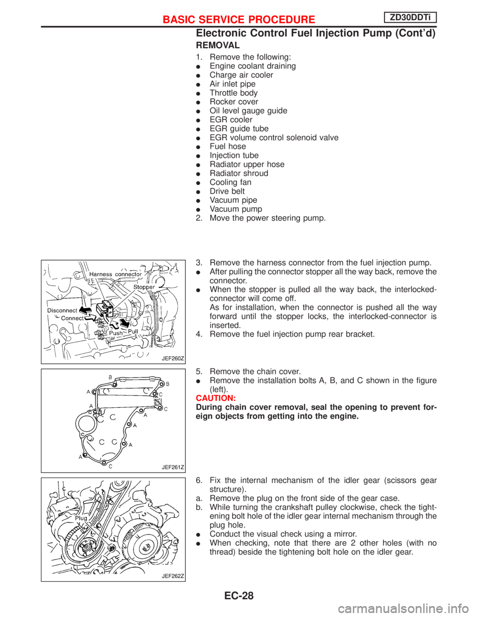
3. Remove the harness connector from the fuel injection pump.
IAfter pulling the connector stopper all the way back, remove the
connector.
IWhen the stopper is pulled all the way back, the interlocked-
connector will come off.
As for installation, when the connector is pushed all the way
forward until the stopper locks, the interlocked-connector is
inserted.
4. Remove the fuel injection pump rear bracket.
5. Remove the chain cover.
IRemove the installation bolts A, B, and C shown in the figure
(left).
CAUTION:
During chain cover removal, seal the opening to prevent for-
eign objects from getting into the engine.
6. Fix the internal mechanism of the idler gear (scissors gear
structure).
a. Remove the plug on the front side of the gear case.
b. While turning the crankshaft pulley clockwise, check the tight-
ening bolt hole of the idler gear internal mechanism through the
plug hole.
IConduct the visual check using a mirror.
IWhen checking, note that there are 2 other holes (with no
thread) beside the tightening bolt hole on the idler gear.
JEF260Z
JEF261Z
JEF262Z
BASIC SERVICE PROCEDUREZD30DDTi
Electronic Control Fuel Injection Pump (Cont'd)
EC-28
Page 701 of 1767
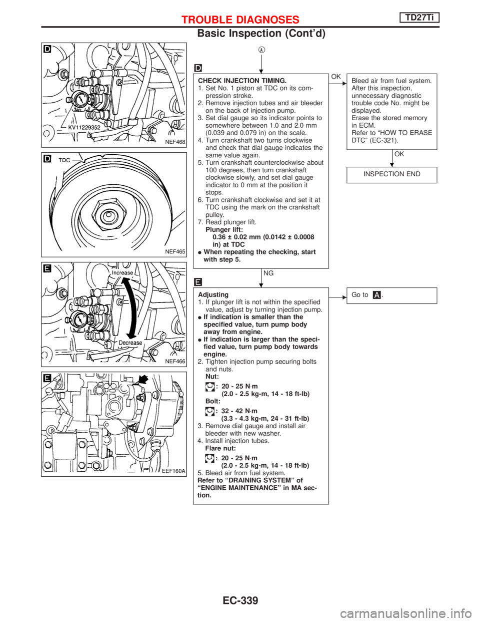
qA
CHECK INJECTION TIMING.
1. Set No. 1 piston at TDC on its com-
pression stroke.
2. Remove injection tubes and air bleeder
on the back of injection pump.
3. Set dial gauge so its indicator points to
somewhere between 1.0 and 2.0 mm
(0.039 and 0.079 in) on the scale.
4. Turn crankshaft two turns clockwise
and check that dial gauge indicates the
same value again.
5. Turn crankshaft counterclockwise about
100 degrees, then turn crankshaft
clockwise slowly, and set dial gauge
indicator to 0 mm at the position it
stops.
6. Turn crankshaft clockwise and set it at
TDC using the mark on the crankshaft
pulley.
7. Read plunger lift.
Plunger lift:
0.36 0.02 mm (0.0142 0.0008
in) at TDC
IWhen repeating the checking, start
with step 5.
NG
EOK
Bleed air from fuel system.
After this inspection,
unnecessary diagnostic
trouble code No. might be
displayed.
Erase the stored memory
in ECM.
Refer to ªHOW TO ERASE
DTCº (EC-321).
OK
INSPECTION END
Adjusting
1. If plunger lift is not within the specified
value, adjust by turning injection pump.
IIf indication is smaller than the
specified value, turn pump body
away from engine.
IIf indication is larger than the speci-
fied value, turn pump body towards
engine.
2. Tighten injection pump securing bolts
and nuts.
Nut:
: 20-25N×m
(2.0 - 2.5 kg-m, 14 - 18 ft-lb)
Bolt:
: 32-42N×m
(3.3 - 4.3 kg-m, 24 - 31 ft-lb)
3. Remove dial gauge and install air
bleeder with new washer.
4. Install injection tubes.
Flare nut:
: 20-25N×m
(2.0 - 2.5 kg-m, 14 - 18 ft-lb)
5. Bleed air from fuel system.
Refer to ªDRAINING SYSTEMº of
ªENGINE MAINTENANCEº in MA sec-
tion.
EGo to.
NEF468
NEF465
NEF466
EEF160A
H
H
H
TROUBLE DIAGNOSESTD27Ti
Basic Inspection (Cont'd)
EC-339