2002 NISSAN TERRANO Oil grade
[x] Cancel search: Oil gradePage 1162 of 1767
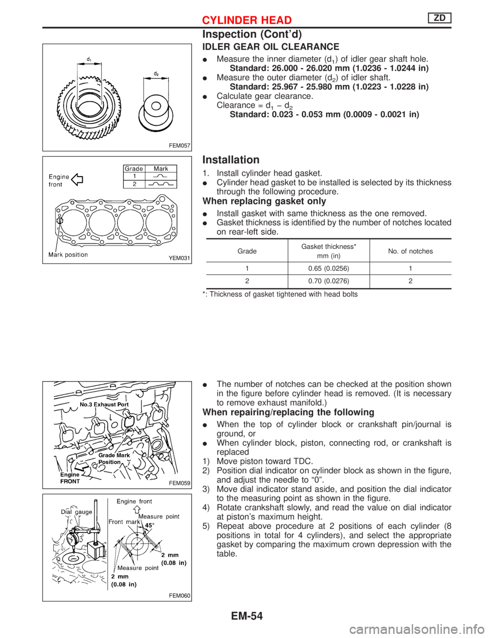
IDLER GEAR OIL CLEARANCE
IMeasure the inner diameter (d1) of idler gear shaft hole.
Standard: 26.000 - 26.020 mm (1.0236 - 1.0244 in)
IMeasure the outer diameter (d
2) of idler shaft.
Standard: 25.967 - 25.980 mm (1.0223 - 1.0228 in)
ICalculate gear clearance.
Clearance = d
1þd2Standard: 0.023 - 0.053 mm (0.0009 - 0.0021 in)
Installation
1. Install cylinder head gasket.
ICylinder head gasket to be installed is selected by its thickness
through the following procedure.
When replacing gasket only
IInstall gasket with same thickness as the one removed.
IGasket thickness is identified by the number of notches located
on rear-left side.
GradeGasket thickness*
mm (in)No. of notches
1 0.65 (0.0256) 1
2 0.70 (0.0276) 2
*: Thickness of gasket tightened with head bolts
IThe number of notches can be checked at the position shown
in the figure before cylinder head is removed. (It is necessary
to remove exhaust manifold.)
When repairing/replacing the following
IWhen the top of cylinder block or crankshaft pin/journal is
ground, or
IWhen cylinder block, piston, connecting rod, or crankshaft is
replaced
1) Move piston toward TDC.
2) Position dial indicator on cylinder block as shown in the figure,
and adjust the needle to ª0º.
3) Move dial indicator stand aside, and position the dial indicator
to the measuring point as shown in the figure.
4) Rotate crankshaft slowly, and read the value on dial indicator
at piston's maximum height.
5) Repeat above procedure at 2 positions of each cylinder (8
positions in total for 4 cylinders), and select the appropriate
gasket by comparing the maximum crown depression with the
table.
FEM057
YEM031
FEM059
FEM060
CYLINDER HEADZD
Inspection (Cont'd)
EM-54
Page 1163 of 1767
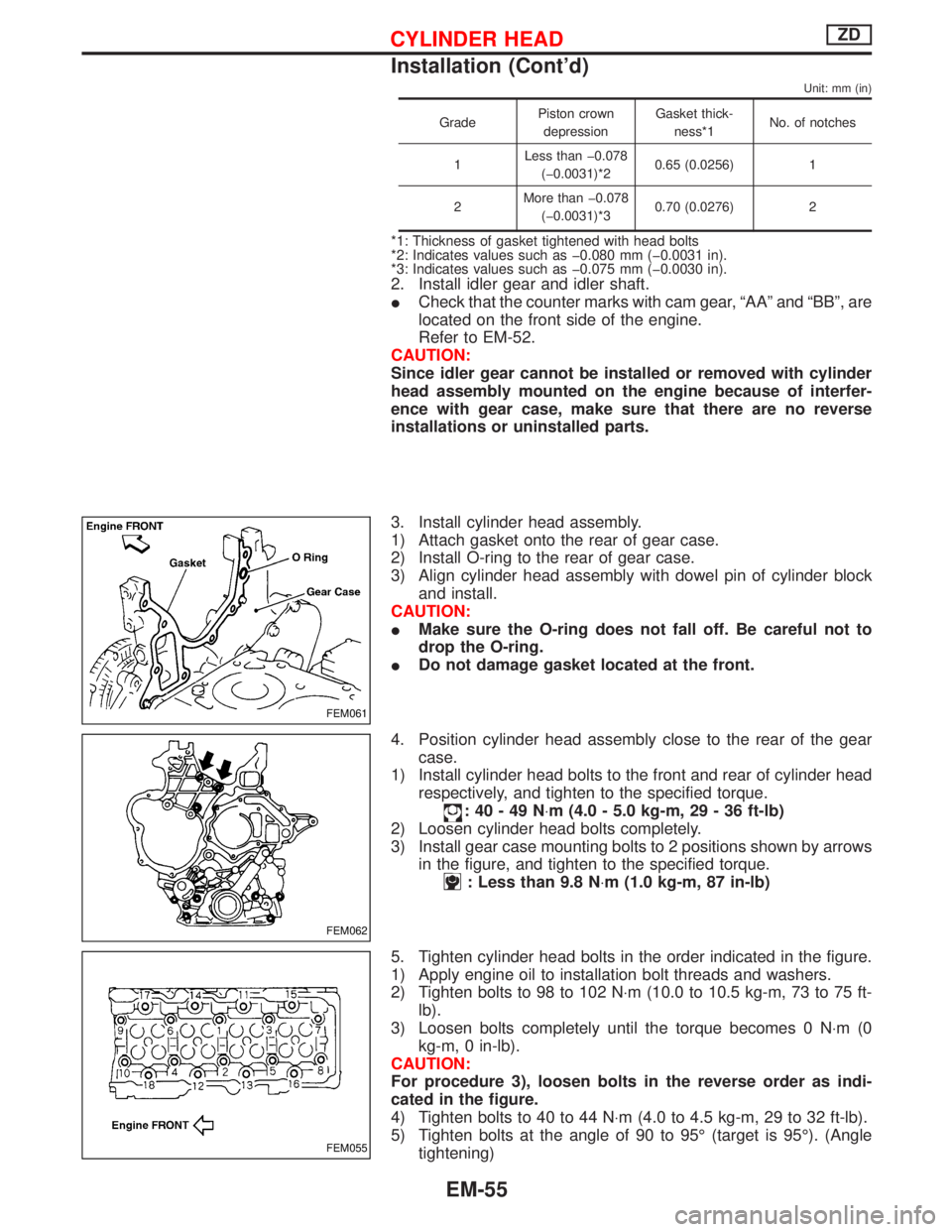
Unit: mm (in)
GradePiston crown
depressionGasket thick-
ness*1No. of notches
1Less than þ0.078
(þ0.0031)*20.65 (0.0256) 1
2More than þ0.078
(þ0.0031)*30.70 (0.0276) 2
*1: Thickness of gasket tightened with head bolts
*2: Indicates values such as þ0.080 mm (þ0.0031 in).
*3: Indicates values such as þ0.075 mm (þ0.0030 in).
2. Install idler gear and idler shaft.
ICheck that the counter marks with cam gear, ªAAº and ªBBº, are
located on the front side of the engine.
Refer to EM-52.
CAUTION:
Since idler gear cannot be installed or removed with cylinder
head assembly mounted on the engine because of interfer-
ence with gear case, make sure that there are no reverse
installations or uninstalled parts.
3. Install cylinder head assembly.
1) Attach gasket onto the rear of gear case.
2) Install O-ring to the rear of gear case.
3) Align cylinder head assembly with dowel pin of cylinder block
and install.
CAUTION:
IMake sure the O-ring does not fall off. Be careful not to
drop the O-ring.
IDo not damage gasket located at the front.
4. Position cylinder head assembly close to the rear of the gear
case.
1) Install cylinder head bolts to the front and rear of cylinder head
respectively, and tighten to the specified torque.
:40-49N×m (4.0 - 5.0 kg-m, 29 - 36 ft-lb)
2) Loosen cylinder head bolts completely.
3) Install gear case mounting bolts to 2 positions shown by arrows
in the figure, and tighten to the specified torque.
: Less than 9.8 N×m (1.0 kg-m, 87 in-lb)
5. Tighten cylinder head bolts in the order indicated in the figure.
1) Apply engine oil to installation bolt threads and washers.
2) Tighten bolts to 98 to 102 N×m (10.0 to 10.5 kg-m, 73 to 75 ft-
lb).
3) Loosen bolts completely until the torque becomes 0 N×m(0
kg-m, 0 in-lb).
CAUTION:
For procedure 3), loosen bolts in the reverse order as indi-
cated in the figure.
4) Tighten bolts to 40 to 44 N×m (4.0 to 4.5 kg-m, 29 to 32 ft-lb).
5) Tighten bolts at the angle of 90 to 95É (target is 95É). (Angle
tightening)
FEM061
FEM062
FEM055
CYLINDER HEADZD
Installation (Cont'd)
EM-55
Page 1176 of 1767
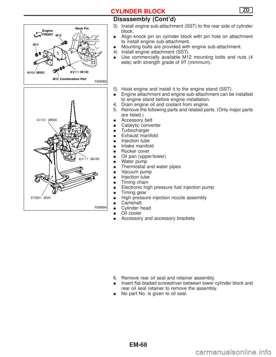
3) Install engine sub-attachment (SST) to the rear side of cylinder
block.
IAlign knock pin on cylinder block with pin hole on attachment
to install engine sub-attachment.
IMounting bolts are provided with engine sub-attachment.
4) Install engine attachment (SST).
IUse commercially available M12 mounting bolts and nuts (4
sets) with strength grade of 9T (minimum).
5) Hoist engine and install it to the engine stand (SST).
IEngine attachment and engine sub-attachment can be installed
to engine stand before engine installation.
4. Drain engine oil and coolant from engine.
5. Remove the following parts and related parts. (Only major parts
are listed.)
IAccessory belt
ICatalytic converter
ITurbocharger
IExhaust manifold
IInjection tube
IIntake manifold
IRocker cover
IOil pan (upper/lower)
IWater pump
IThermostat and water pipes
IVacuum pump
IInjection tube
ITiming chain
IElectronic high pressure fuel injection pump
ITiming gear
IHigh pressure injection nozzle assembly
ICamshaft
ICylinder head
IOil cooler
IAccessory and accessory brackets
6. Remove rear oil seal and retainer assembly.
IInsert flat-bladed screwdriver between lower cylinder block and
rear oil seal retainer to remove the assembly.
INo part No. is given to oil seal.
FEM083
FEM084
CYLINDER BLOCKZD
Disassembly (Cont'd)
EM-68
Page 1182 of 1767
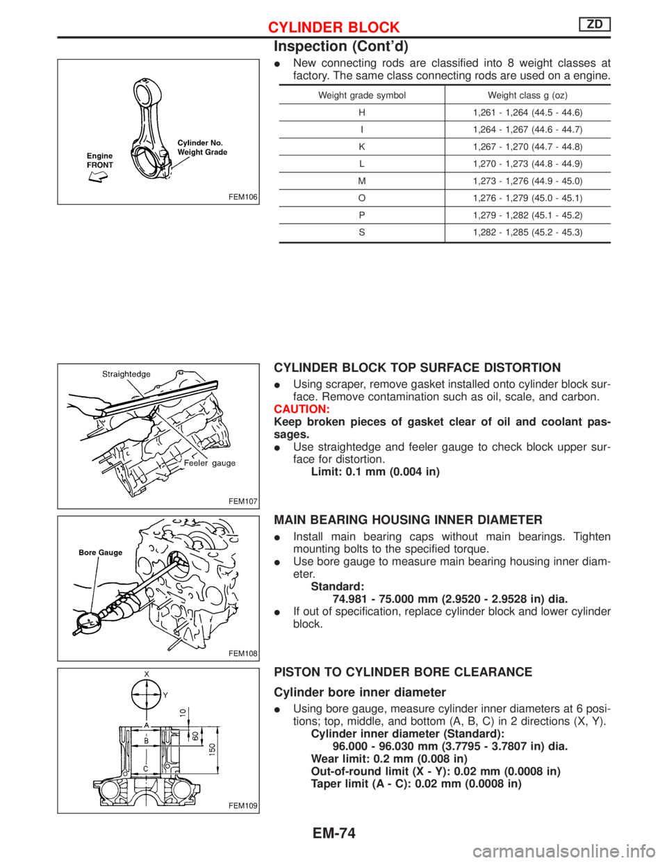
INew connecting rods are classified into 8 weight classes at
factory. The same class connecting rods are used on a engine.
Weight grade symbol Weight class g (oz)
H 1,261 - 1,264 (44.5 - 44.6)
I 1,264 - 1,267 (44.6 - 44.7)
K 1,267 - 1,270 (44.7 - 44.8)
L 1,270 - 1,273 (44.8 - 44.9)
M 1,273 - 1,276 (44.9 - 45.0)
O 1,276 - 1,279 (45.0 - 45.1)
P 1,279 - 1,282 (45.1 - 45.2)
S 1,282 - 1,285 (45.2 - 45.3)
CYLINDER BLOCK TOP SURFACE DISTORTION
IUsing scraper, remove gasket installed onto cylinder block sur-
face. Remove contamination such as oil, scale, and carbon.
CAUTION:
Keep broken pieces of gasket clear of oil and coolant pas-
sages.
IUse straightedge and feeler gauge to check block upper sur-
face for distortion.
Limit: 0.1 mm (0.004 in)
MAIN BEARING HOUSING INNER DIAMETER
IInstall main bearing caps without main bearings. Tighten
mounting bolts to the specified torque.
IUse bore gauge to measure main bearing housing inner diam-
eter.
Standard:
74.981 - 75.000 mm (2.9520 - 2.9528 in) dia.
IIf out of specification, replace cylinder block and lower cylinder
block.
PISTON TO CYLINDER BORE CLEARANCE
Cylinder bore inner diameter
IUsing bore gauge, measure cylinder inner diameters at 6 posi-
tions; top, middle, and bottom (A, B, C) in 2 directions (X, Y).
Cylinder inner diameter (Standard):
96.000 - 96.030 mm (3.7795 - 3.7807 in) dia.
Wear limit: 0.2 mm (0.008 in)
Out-of-round limit (X - Y): 0.02 mm (0.0008 in)
Taper limit (A - C): 0.02 mm (0.0008 in)
FEM106
FEM107
FEM108
FEM109
CYLINDER BLOCKZD
Inspection (Cont'd)
EM-74
Page 1201 of 1767
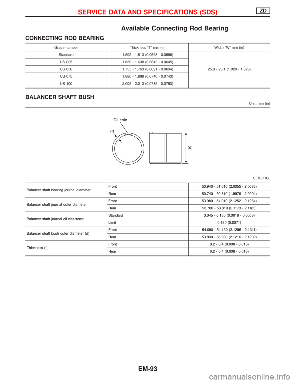
Available Connecting Rod Bearing
CONNECTING ROD BEARING
Grade number Thickness ªTº mm (in) Width ªWº mm (in)
Standard 1.505 - 1.513 (0.0593 - 0.0596)
25.9 - 26.1 (1.020 - 1.028) US 025 1.630 - 1.638 (0.0642 - 0.0645)
US 050 1.755 - 1.763 (0.0691 - 0.0694)
US 075 1.880 - 1.888 (0.0740 - 0.0743)
US 100 2.005 - 2.013 (0.0789 - 0.0793)
BALANCER SHAFT BUSH
Unit: mm (in)
SEM371G
Balancer shaft bearing journal diameterFront 50.940 - 51.010 (2.0055 - 2.0083)
Rear 50.740 - 50.810 (1.9976 - 2.0004)
Balancer shaft journal outer diameterFront 53.980 - 54.010 (2.1252 - 2.1264)
Rear 53.780 - 53.810 (2.1173 - 2.1185)
Balancer shaft journal oil clearanceStandard 0.045 - 0.135 (0.0018 - 0.0053)
Limit 0.180 (0.0071)
Balancer shaft bush outer diameter (d)Front 54.090 - 54.130 (2.1295 - 2.1311)
Rear 53.890 - 53.930 (2.1216 - 2.1232)
Thickness (t)Front 0.2 - 0.4 (0.008 - 0.016)
Rear 0.2 - 0.4 (0.008 - 0.016)
SERVICE DATA AND SPECIFICATIONS (SDS)ZD
EM-93
Page 1256 of 1767
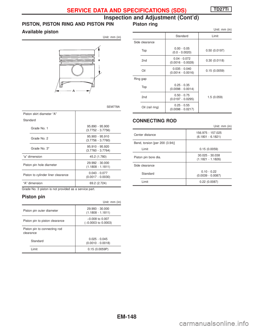
PISTON, PISTON RING AND PISTON PIN
Available piston
Unit: mm (in)
SEM778A
Piston skirt diameter ªAº
Standard
Grade No. 195.890 - 95.900
(3.7752 - 3.7756)
Grade No. 295.900 - 95.910
(3.7756 - 3.7760)
Grade No. 3*95.910 - 95.920
(3.7760 - 3.7764)
ªaº dimension 45.2 (1.780)
Piston pin hole diameter29.992 - 30.000
(1.1808 - 1.1811)
Piston to cylinder liner clearance0.043 - 0.077
(0.0017 - 0.0030)
ªAº dimension 69.2 (2.724)
Grade No. 3 piston is not provided as a service part.
Piston pin
Unit: mm (in)
Piston pin outer diameter29.993 - 30.000
(1.1808 - 1.1811)
Piston pin to piston clearanceþ0.008 to 0.007
(þ0.0003 to 0.0003)
Piston pin to connecting rod
clearance
Standard0.025 - 0.045
(0.0010 - 0.0018)
Limit 0.15 (0.0059P)
Piston ring
Unit: mm (in)
Standard Limit
Side clearance
To p0.00 - 0.05
(0.0 - 0.0020)0.50 (0.0197)
2nd0.04 - 0.072
(0.0016 - 0.0028)0.30 (0.0118)
Oil0.035 - 0.040
(0.0014 - 0.0016)0.15 (0.0059)
Ring gap
To p0.25 - 0.35
(0.0098 - 0.0014)
1.5 (0.059) 2nd0.50 - 0.75
(0.0197 - 0.0295)
Oil (rail ring)0.25 - 0.55
(0.0098 - 0.0217)
CONNECTING ROD
Unit: mm (in)
Center distance156.975 - 157.025
(6.1801 - 6.1821)
Bend, torsion [per 200 (3.94)]
Limit 0.15 (0.0059)
Piston pin bore dia.30.025 - 30.038
(1.1821 - 1.1826)
Side clearance
Standard0.10 - 0.22
(0.0039 - 0.0087)
Limit 0.22 (0.0087)
SERVICE DATA AND SPECIFICATIONS (SDS)TD27Ti
Inspection and Adjustment (Cont'd)
EM-148
Page 1489 of 1767
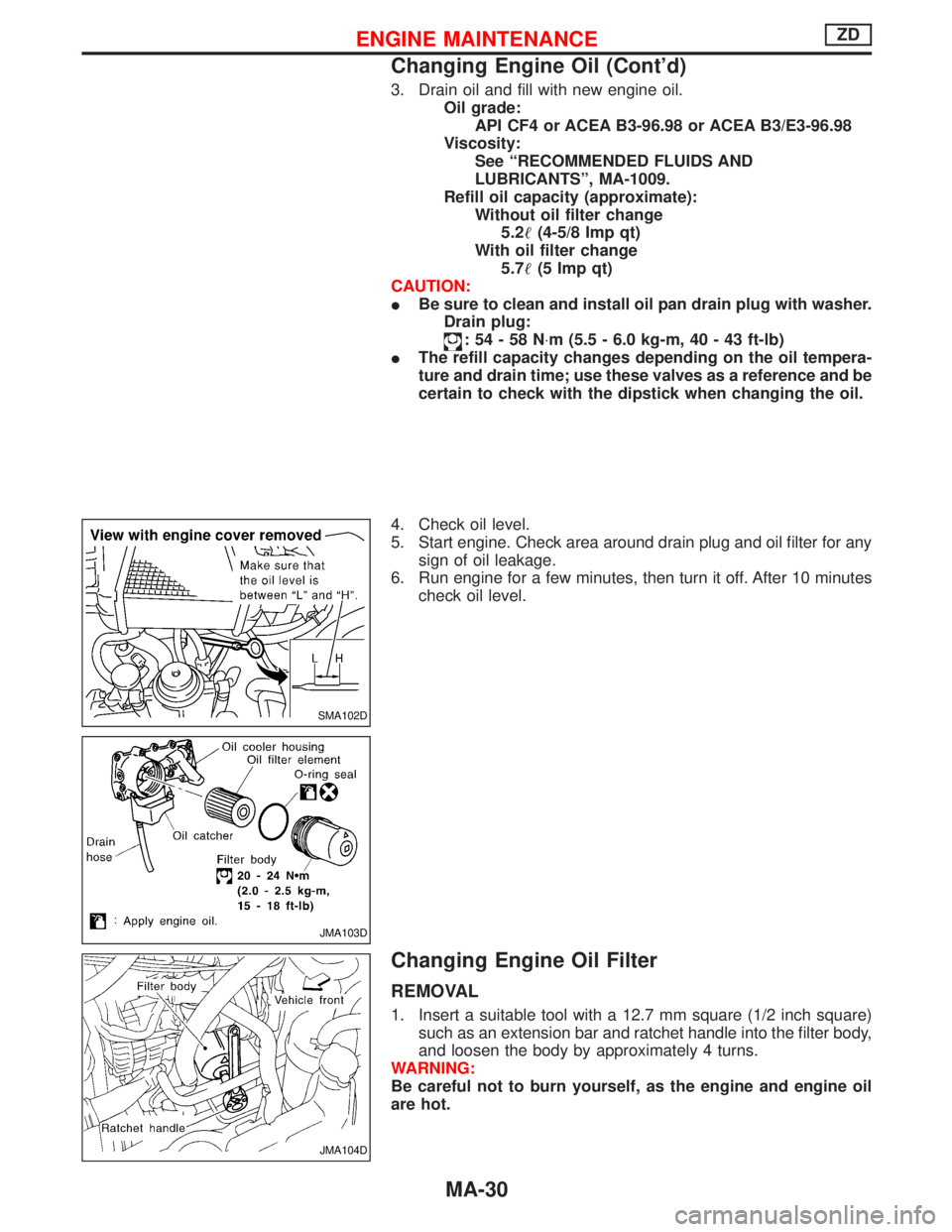
3. Drain oil and fill with new engine oil.
Oil grade:
API CF4 or ACEA B3-96.98 or ACEA B3/E3-96.98
Viscosity:
See ªRECOMMENDED FLUIDS AND
LUBRICANTSº, MA-1009.
Refill oil capacity (approximate):
Without oil filter change
5.2(4-5/8 Imp qt)
With oil filter change
5.7(5 Imp qt)
CAUTION:
IBe sure to clean and install oil pan drain plug with washer.
Drain plug:
:54-58N×m (5.5 - 6.0 kg-m, 40 - 43 ft-lb)
IThe refill capacity changes depending on the oil tempera-
ture and drain time; use these valves as a reference and be
certain to check with the dipstick when changing the oil.
4. Check oil level.
5. Start engine. Check area around drain plug and oil filter for any
sign of oil leakage.
6. Run engine for a few minutes, then turn it off. After 10 minutes
check oil level.
Changing Engine Oil Filter
REMOVAL
1. Insert a suitable tool with a 12.7 mm square (1/2 inch square)
such as an extension bar and ratchet handle into the filter body,
and loosen the body by approximately 4 turns.
WARNING:
Be careful not to burn yourself, as the engine and engine oil
are hot.
SMA102D
JMA103D
JMA104D
ENGINE MAINTENANCEZD
Changing Engine Oil (Cont'd)
MA-30